Ordinance nº 3, 21st July 2004 (Bulgaria).
Basic principles for structural design and their applied actions. Section VI: Wind loads.
Code implemented in CYPECAD.
Implemented in the Portal Frame Generator as of the 2010.m version.


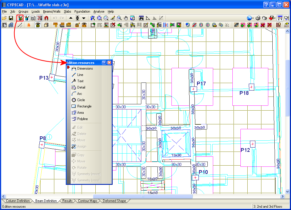
Edition resources
Two new options have been added to the Edition resources dialogue box:
- Circle
Draws a circle without dimensions by indicating the radius or diameter - Polyline
Draws an open or closed polyline
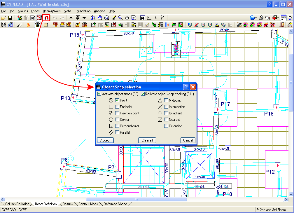
Object snap tracking
New object snap tracking options have been included in the Object snap selection box (perpendicular, parallel and extension) to be used with DXF and DWG templates.
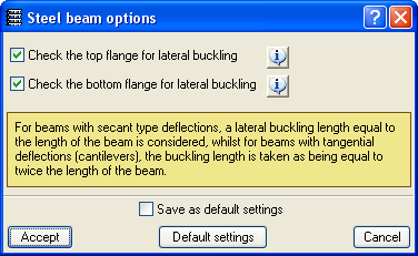
Lateral buckling of the top flange of steel beams
In previous versions, CYPECAD checked the bottom flange of steel beams not supporting floor slabs on that flange along their entire length, such as for example: beams below slabs, isolated beams, beams next to openings, or beams whose top flange projects above the floor slab.
Checking of both webs is activated in the Options for steel beams dialogue box which can be accessed from the Job menu in the Beam Definition tab > Beam options > Steel beam options.
Different building use for each floor group
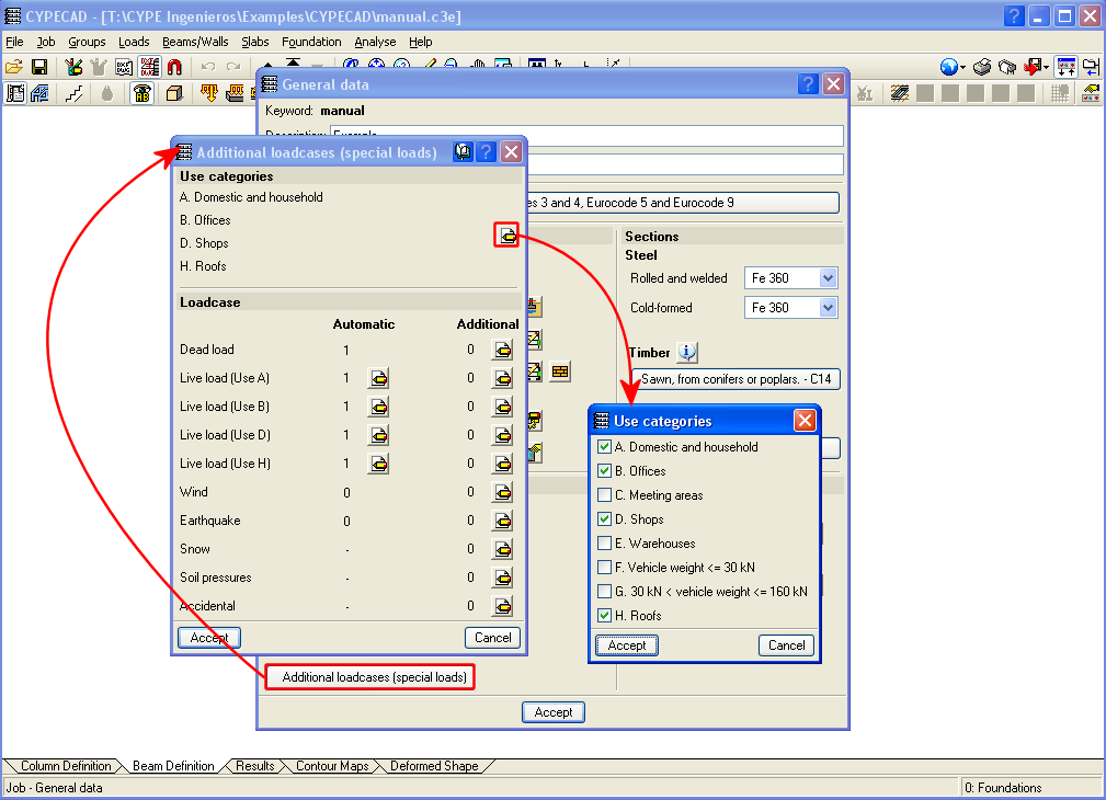
Now in CYPECAD, different use categories can be defined for each floor group of the structure. Examples of use categories include: dwellings, shops, warehouses, garages, etc. The number of use categories the program allows to choose amongst depends on the selected code. For example, the use categories for the Eurocode are:
- A. Domestic and household
- B. Offices
- C. Meeting areas
- D. Shops
- E. Warehouses
- F. Vehicle weight <= 30 kN
- G. 30 kN < vehicle weight <= 160 kN
- H. Roofs
For the program, a use category consists of a group of live loadcases, be they automatic or additional, which combine with the other loadcases that have been defined in the job with the same combination coefficients.
This way, the live load combinations for each use category can be analysed correctly amongst all the use categories and the remaining loadcases of the job for which different use categories exist per floor.
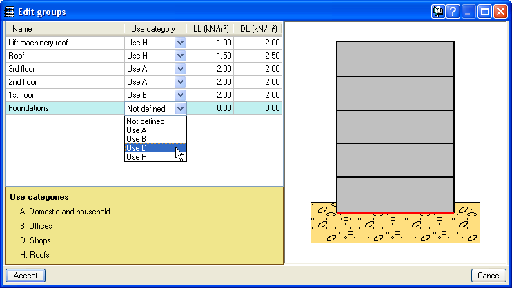
The use categories can be selected in the Additional loadcases (special loads) dialogue box within the General data window (Job > General data > Additional loadcases (special loads)). The categories that are selected in this dialogue box are assigned to each floor group in the Edit groups dialogue box which opens by selecting the Loads menu within the Beam Definition tab > Loads in groups or in the Column Definition tab > Floors/Groups > Edit groups.
Different use categories can also be defined for a floor group. To do so, simply do not introduce a live load for the group and once the geometry of the floor group has been defined, introduce the live loads at different positions on the group, assigned to the corresponding loadcase.
The user should bear in mind that the more use categories are defined for a job, the more loadcase combinations the program will create, and so, the time taken to analyse the job will be substantially longer.