Update history​​

CYPECAD

ASCE/SEI 7-05 (USA International): Minimum Design Loads for Buildings and Other Structures.
Code implemented in CYPECAD.
Implemented in the Portal frame generator as of the 2010.m version.
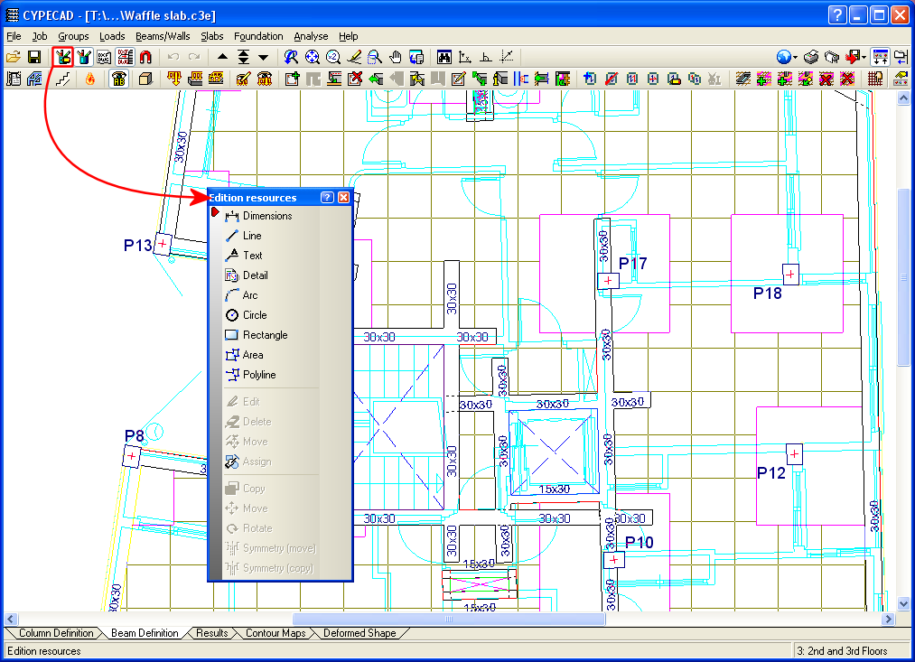
  • IS 456: 2000 (ACI318M-08) (India): Plain and Reinforced Concrete – Code of Practice.
    Implemented in CYPECAD and Metal 3D.
    Includes materials, steel bar diameters and load combinations of the code with the design criteria of the ACI 318M-08 (USA) code. The design criteria of the IS 456: 2000 code will be included in upcoming updates of the 2011 version.

CFE 2008 (Mexico): Manual de diseño de Obras Civiles. Diseño por sismo. Comisión Federal de Electricidad. México 2008.
Code implemented in CYPECAD and Metal 3D.

R.N.V.99 D.T.R. C 2-4.7 (Algeria)
Code implemented in CYPECAD.
Implemented in the Portal Frame Generator as of the 2010.b version.

Ordinance nº 3, 21st July 2004 (Bulgaria).
Basic principles for structural design and their applied actions. Section VI: Wind loads.
Code implemented in CYPECAD.
Implemented in the Portal Frame Generator as of the 2010.m version.

Eurocode 1 (National application document for Belgium) - prNBN EN 1991-1-4 ANB (2009).
Code implemented in CYPECAD.
Implemented in the Portal Frame Generator as of the 2010.a version.

DIN 18800:2008-11 (Alemania): Deutsches Institut für Normung. Stahlbauten.
Code implemented in CYPECAD and Metal 3D for the following sections:

Rolled and welded steel

  • I
  • C
  • L
  • Rectangular hollow section
  • Circular hollow section

Cold-formed steel

  • C and stiffened C
  • L and stiffened L
  • Rectangular hollow section
  • Circular hollow section

The following elements have been implemented when exporting to Tekla structures:

  • Concrete beams and columns of CYPECAD, and concrete bars of Metal 3D and integrated 3D structures of CYPECAD. The elements that are exported have rectangular, circular, T or L sections.
  • Special extruded aluminium sections
  • Trims at hollow section ends processed by the new Joints V module.
    These elements are exported as macros type “Tube-Saddle+Hole” for versions 15.0 SR1 and 16.0 of Tekla Structures.

Two new options have been added to the Edition resources dialogue box:

  • Circle
    Draws a circle without dimensions by indicating the radius or diameter
  • Polyline
    Draws an open or closed polyline
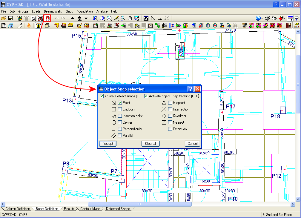
New object snap tracking options have been included in the Object snap selection box (perpendicularparallel and extension) to be used with DXF and DWG templates.
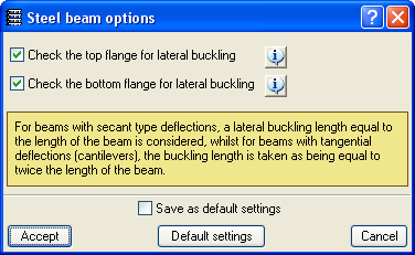
Horizontal or sloped planes defined in the Sloped floor slabs/El. Changes (Column Definition tab > Groups > Sloped floor slabs/ El. Changes) can now be assigned to the tops of walls. This way, the user can assign an elevation change or a slope to the top of a wall even if it does not support a floor slab.

In previous versions, CYPECAD checked the bottom flange of steel beams not supporting floor slabs on that flange along their entire length, such as for example: beams below slabs, isolated beams, beams next to openings, or beams whose top flange projects above the floor slab.

Checking of both webs is activated in the Options for steel beams dialogue box which can be accessed from the Job menu in the Beam Definition tab > Beam options > Steel beam options.

CYPE Mentor