Update history​​

CYPECAD

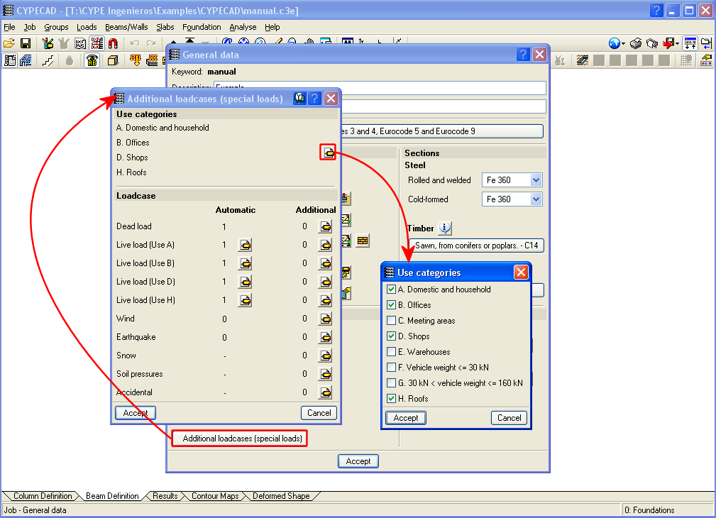
Now in CYPECAD, different use categories can be defined for each floor group of the structure. Examples of use categories include: dwellings, shops, warehouses, garages, etc. The number of use categories the program allows to choose amongst depends on the selected code. For example, the use categories for the Eurocode are:

  • A. Domestic and household
  • B. Offices
  • C. Meeting areas
  • D. Shops
  • E. Warehouses
  • F. Vehicle weight <= 30 kN
  • G. 30 kN < vehicle weight <= 160 kN
  • H. Roofs

For the program, a use category consists of a group of live loadcases, be they automatic or additional, which combine with the other loadcases that have been defined in the job with the same combination coefficients.

This way, the live load combinations for each use category can be analysed correctly amongst all the use categories and the remaining loadcases of the job for which different use categories exist per floor.

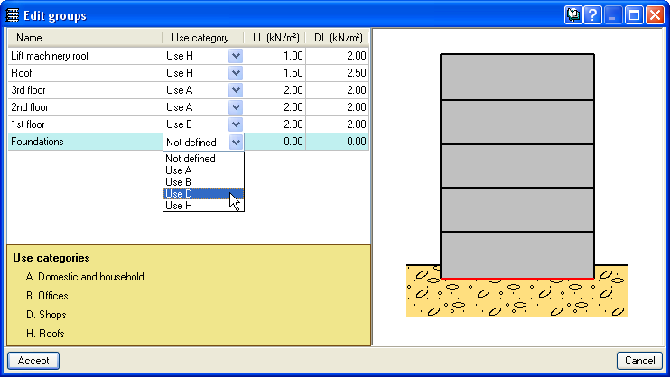
The use categories can be selected in the Additional loadcases (special loads) dialogue box within the General data window (Job > General data > Additional loadcases (special loads)). The categories that are selected in this dialogue box are assigned to each floor group in the Edit groups dialogue box which opens by selecting the Loads menu within the Beam Definition tab > Loads in groups or in the Column Definition tab > Floors/Groups > Edit groups.

Different use categories can also be defined for a floor group. To do so, simply do not introduce a live load for the group and once the geometry of the floor group has been defined, introduce the live loads at different positions on the group, assigned to the corresponding loadcase.

The user should bear in mind that the more use categories are defined for a job, the more loadcase combinations the program will create, and so, the time taken to analyse the job will be substantially longer.

Changes have been carried out in the calculation method used to obtain the forces of footings “with external fixity”, for footings, pile caps, strap and tie beams.

The current design can differ from previous versions. Now, once the reactions at the base of the supporting elements of the structure are obtained (columns, shear walls and walls), a model is created will all the foundation elements “with external fixity” and its beams, represented by its stiffness matrix. The stiffness matrix, together with the loadcases defined as loads acting on the foundation (reactions that have been obtained), is resolved using frontal methods to obtain the displacements and forces of all the elements. By doing this, the stiffness of all the elements intervene and interact with one another.

Composite sections made up of simple sections which are already implemented can be used with the following codes: AISI/NASPEC-2007 (LFRD) (USA), AISI/NASPEC-2007 (LFRD) (Mexico) and CAN/CSA S136-07 (Canada) (as of the 2011.a version). The simple sections and their corresponding composition to create composite sections are:

  • For simple cold-formed C and stiffened cold-formed C sections:
    • Double welded in a box
    • Double in a box with batten plates
    • Double in a box with generic joint
    • Double welded in I
    • Double in I with plates
    • Double in I with generic joint
  • For Rectangular cold-formed box and Square cold-formed box
    • Double with generic joint
    • Four with generic joint
  • Cold-formed angle and Symmetrical cold-formed angle
    • Double welded in a box
    • Double in a box with generic joint
    • Double welded in T
    • Double in T with generic joint
    • Double in U with generic joint
    • Double in cross with generic joint
  • Channel with stiffened web
    • Double welded in a box
    • Double in box with cover plates
    • Double in box with batten plates
    • Double in box with generic joint
    • Double welded in I
    • Double in I with plates
    • Double in I with generic joint
  • Eurocode 3
    The corrections undertaken by the CEN (European Committee for Standardization) have been implemented in the following documents (as of the 2011.a version)
    • EN 1993-1-1:2005/AC:2009
    • EN 1993-1-2:2005/AC:2009
    • EN 1993-1-3:2006/AC:2009
    • EN 1993-1-5:2006/AC:2009
    These implementations affect the use of Eurocode 3 for any of the countries that may be selected with this code (International, Bulgaria, France and Portugal).
    The following National documents of Eurocode 3 for France have been implemented:
    • NF EN 1993-1-2:2005/NA:2007
    • NF EN 1993-1-3:2007/NA:2007
    • NF EN 1993-1-5:2007/NA:2007

Eurocode 3
The corrections undertaken by the CEN (European Committee for Standardization) have been implemented in the following documents (as of the 2011.a version)

  • EN 1993-1-1:2005/AC:2009
  • EN 1993-1-2:2005/AC:2009
  • EN 1993-1-5:2006/AC:2009
  • EN 1993-1-8:2005/AC:2009

These implementations affect the use of Eurocode 3 for any of the countries that may be selected with this code (International, Bulgaria, France and Portugal).

The following National documents of Eurocode 3 for France have been implemented:

  • NF EN 1993-1-2:2005/NA:2007
  • NF EN 1993-1-5:2007/NA:2007

CPE INEN 5:2001 (Ecuador)
Construction code of Ecuador
General Design Requirements: Seismic danger, Design Spectrum and Minimum Calculation Requirements for Seismic-Resistant Design.
Implemented in CYPECAD and Metal 3D (as of the 2011.a version).

IS:875: (Part3) – 1987 (Reaffirmed 1997) (India)
Code of Practice for Design Loads (other than earthquake) for Buildings and Structures. Part 3 - Wind Loads.
Implemented in CYPECAD and the Portal frame generator (as of the 2011.a version).

As of the 2011.a version, the 3D views of CYPECAD and Metal 3D contain a new option which displays elements with textures resembling the real colours of the material they are made out of. The user can choose to represent the 3D view with or without the materials:

  • Without materials
    Displays the materials that existed until now, which differentiated the elements of the 3D view, even if they consisted of the same material.
  • With materials
    Displays the elements of the 3d view with textures which resemble their real colours.

The Advanced design of surface foundations module complements the Footings and Pile caps modules when these are used in CYPECAD. Allows for the design of foundations composed of footings and pile caps with special element intersections (strap and tie beam intersections), geometrical trimming of footings, and application of line, point and surface loads on footings, pile caps and strap and tie beams. In the case of Metal 3D, this module only allows for trimming of the footing geometry to be carried out.

More information on this module can be found at:  Advanced design of surface foundations

The Joints V. Flat trusses with hollow structural sections module for CYPECAD, its Integrated 3D structures and Metal 3D, carries out an automatic analysis and design of coplanar hollow structural section connections, like those which are usually provided in flat trusses.

More information on this module can be found at: Joints V. Flat trusses with hollow structural sections.

The new module Joints IV. Bolted. Building frames with rolled and welded steel I sections allows for the automatic design and analysis of the most common type of bolted connections of rolled and welded steel I sections in CYPECAD, its Integrated 3D structures and Metal 3D. More information can be found in the Bolted connections of rolled and welded steel I sections for building frames section (implemented codes, type of implemented connections…).

  • Export of aluminium elements

Metal 3D and Integrated 3D structures of CYPECAD allow for designed aluminium elements to be exported to Tekla StructuresTecnoMetal 4D and to CIS/2 format.

More information on the elements CYPECAD, Metal 3D and Integrated 3D structures of CYPECAD can export to these programs can be found at Export to Tekla Structures, Export to TecnoMetal 4D and Export to CIS/2 format.

CYPE Mentor