
Algerian Seismic Loading Code RPA 99 / VERSION 2003 (Algeria)
Implemented in CYPECAD and Metal 3D.
Update history

CYPECAD
Code implementation. Algerian Seismic Loading Code RPA 99 / VERSION 2003 (Algeria)
- Published on
- 2009.1.m
Code check reports on rolled steel sections for Eurocode 3 (France) - NF EN 1993 – 1-1/NA: 2007-05
- The number of codes is increased for which the detailed check reports on ultimate limit states of welded and rolled steel sections are obtained. These reports are available for the following codes and steel types:
- Rolled and welded sections:
- CTE DB SE-A (Spain)
- CAN/CSA S16-01 (Canada)
- Eurocode 3 (Generic, Bulgaria and Portugal)
- Eurocode 3 (France) - NF EN 1993-1-1/NA: 2007-05 (newly implemented)
- Cold formed steel sections
- NBR 14762 (Brazil)
- Published on
- 2009.1.j
Rotational stiffness calculations for bolted connections
As of the 2009.1.g version, users may introduce a value for the rotational stiffness at the ends of elements using the Fixity at ends option, located in the Bar menu. Metal 3D calculates the initial rotational stiffness of elements fixed to bolted connections which have been designed and displays them in the Joints report so users may compare the value to that introduced.
As of the 2009.1.j version, Metal 3D compares the rotational stiffnesses introduced by the user and those proposed by the program, and displays the comparison in an agile and efficient way using the Rotational stiffness option located in the Joints menu. This option allows the user to automatically assign the rotational stiffnesses proposed by the program as well as review them to decide which rotational stiffnesses to adopt.
- Published on
- 2009.1.j
Improvements in the use of the B.A.E.L. 91 code
- Ultimate limit state combinations for failure
The Use or Use category and Snow level can be selected so the program may automatically generate the load combinations (in accordance with the selection that has been carried out) for the analysis depending on the ultimate limit states for failure of each material (concrete, foundation concrete, cold formed steel, rolled steel and wood). To do so, new options have been implemented in the Limit states dialogue (Job > General data > Limit states (combinations) button) which allow for the Use and Snow level to be selected for the various materials.
Additionally, two options have been incorporated in the same dialogue box which generate the combinations of the BAEL 91 code bearing in mind the earthquake code in use:- BAEL 91 option
The load combinations are generated taking into account the PS 92 earthquake code (France) - RPS 2000 option
The load combinations are generated taking into account the RPS 2000 earthquake code (Morocco).
- BAEL 91 option
- Published on
- 2009.1.j
Joists
- Matching of joist top reinforcement and positive moments for all the floor groups of the building
It is possible to match the top reinforcement of joists and their positive moments on all floor groups without the need of having to change to another group. To do so, the commands Match top reinforcement (Results tab > Joists > [Top reinf.] Match) and Match joists (Results tab > Joists > [Bottom reinf] Match) contain two options: Match in all groups and Match in current group. - Joist force diagrams per rib or per metre slab width
The joist force diagrams can be viewed with their values per rib or per metre slab width. The way in which the results are expressed can be configured for viewing on screen as well as for the joist force reports:- On screen
In the Forces in joists dialogue box (Results tab > Envelopes > Forces in joists) two options have been included: Values per rib and Values per metre width - In joist force reports
In the Force envelopes report (from any tab > File > Print > Job report > Forces in joists > select group(s)) the Values per rib and Values per metre width options can also be activated.
- On screen
- Published on
- 2009.1.j
Detailed reports on ultimate limit state checks carried out on welded and rolled steel sections introduced in Integrated 3D structures in CYPECAD and in Metal 3D
- As of the 2009.1.h version, it is possible to obtain detailed reports on ultimate limit state checks carried out on welded and rolled steel sections in Integrated 3D structures in CYPECAD and in Metal 3D
As of the 2009.1.j version, it is also possible to obtain detailed reports on ultimate limit state checks carried out on welded and rolled steel sections introduced in CYPECAD (columns and beams)
To view these reports, having analysed the job, click on the following options:- Columns
Results tab > Columns > Edit > select steel column > U.L.S. button
Or alternatively:
Column Definition tab > Introduction > Columns, shear walls and starts > Design button > select steel column > U.L.S. button - Beams
Results tab > Beams/Walls > Beam errors > select steel beam > U.L.S. checks button - Summarised column and beam reports
Click on the following option from any tab File> Print > Job report > U.L.S. checks for beams and columns.
- Columns
- Published on
- 2009.1.j
Detailed ultimate limit state check reports
We have augmented the number of building codes for which you can now obtain USL calculations for both rolled and welded steel members. The calculations are available for the following building codes:
- Rolled and welded steel members:
- CTE DB SE-A (Spain)
- CAN/CSA S16-01 (Canada)
- Eurocode 3 (Generic, Bulgaria, and Portugal)
- Cold formed steel members:
- NBR 14762 (Brazil)
- Published on
- 2009.1.i
Code implementation. Decree #2, 23.07.2007 (Bulgaria) and CSRC-2002 (Costa Rica)
We have recently implemented the following building codes:
- Seismic Codes:
- Decree #2, 23.07.2007 (Bulgaria)
- CSRC-2002 (Costa Rica)
- Published on
- 2009.1.i
Code implementation. ACI 318M-08 (USA), CIRSOC 201 - 2005 (Argentina) and Eurocode 2 (Bulgaria)
We have recently implemented the following building codes:
- Concrete Codes:
- ACI 318M-08 (USA)
- CIRSOC 201 - 2005 (Argentina)
- Eurocódigo 2 (Bulgaria)
- Published on
- 2009.1.i
Joints
New bolted connections
- Beam joint type: a main continuous element to which one or two orthogonal elements are pinned to it.
- Two beam connection (with or without a bottom haunch) fixed to the flanges of a column (continuous or non-continuous).
- Two beam connection (with or without a bottom haunch) fixed to the flanges of a column (continuous or non-continuous) with an orthogonal beam pinned to the web of the column.
- Two beam connection (with or without a bottom haunch) fixed to the flanges of a column (continuous or non-continuous) with two orthogonal beams pinned to the web of the column.
New options for connection design
- Stiffeners at haunch ends
Stiffeners may be used at haunch ends in column-beamconnections and at ridge connections even though they may not be required in the design calculation. These two options can be activated in the Options dialogue (Joints > Options) which now contains two tabs:- Bolts: Contains bolt design options. These options were available in previous versions.
- Stiffeners: Contains the two new options that force the program to always provide stiffeners in column-beam and ridge connections.
- Baseplate options
The same design options that are used in the Baseplates module are used for the baseplate design in the Joints I module, except for the type of anchorage of the bolt to the plate. These options are configured in the menu Baseplates > Options.
More information on the properties of the two Metal 3D baseplate design modules can be found in the Baseplates section.
Improvement in the joints analysis period
The time required for the joints design has been reduced with the use of multiprocessors (the user must have one of the two following modules: Parallel analysis with two processors or Parallel analysis with four processors).
Welded connection design in accordance to the ABNT NBR 8800:2008 (Brazil) code
Welded connection design has been updated for Brazil in accordance to the ABNT NBR 8800:2008 code (Projecto de estruturas de aço e de estruturas mistas de aço e concreto de edifícios).
- Published on
- 2009.1.h
Detailed ultimate limit state check reports
- Metal 3D and CYPECAD’s Integrated 3D structures generate detailed ultimate limit state check reports of rolled and welded steel sections for the CTE DB SE-A (Spain) and CAN/CSA S16-01 (Canada) codes, and for cold formed steel sections for the NBR 14762 (Brazil) code.
These reports contain all the checks carried out by the program for the section design and therefore constitute an important document with which the user can:- Verify the design of the sections
- Optimise the design of the sections
The level of detail of these reports also provides an informative document, allowing the user to know all the checks to which the section has been submitted.
More information can be found on these documents in the detailed ultimate limit state check reports.
- Published on
- 2009.1.h
Stairs
Free typology
Each flight between floors of stairwells can be defined using any typology that is composed of any of the following elements:
 Straight flight
- Intermediate landing
- Quarter turn landing
- Half turn landing
 Straight flight
 Intermediate landing
 Quarter turn landing
 Half turn landing
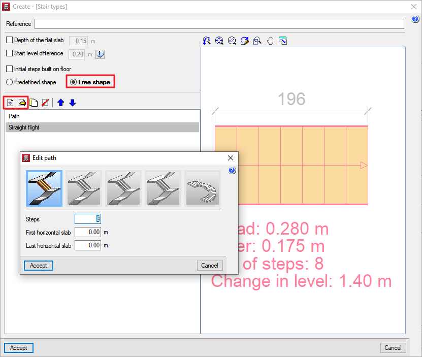
The free stairs typology can be defined by activating the Free shape option in the Create or Edit [Stair typology] dialogue box. If a flight of stairs is then added (![]() ) or edited (
) or edited (![]() ) from the Path list, the New path dialogue box appears where any of the elements forming the flight of stairs can be selected.
) from the Path list, the New path dialogue box appears where any of the elements forming the flight of stairs can be selected.
- Published on