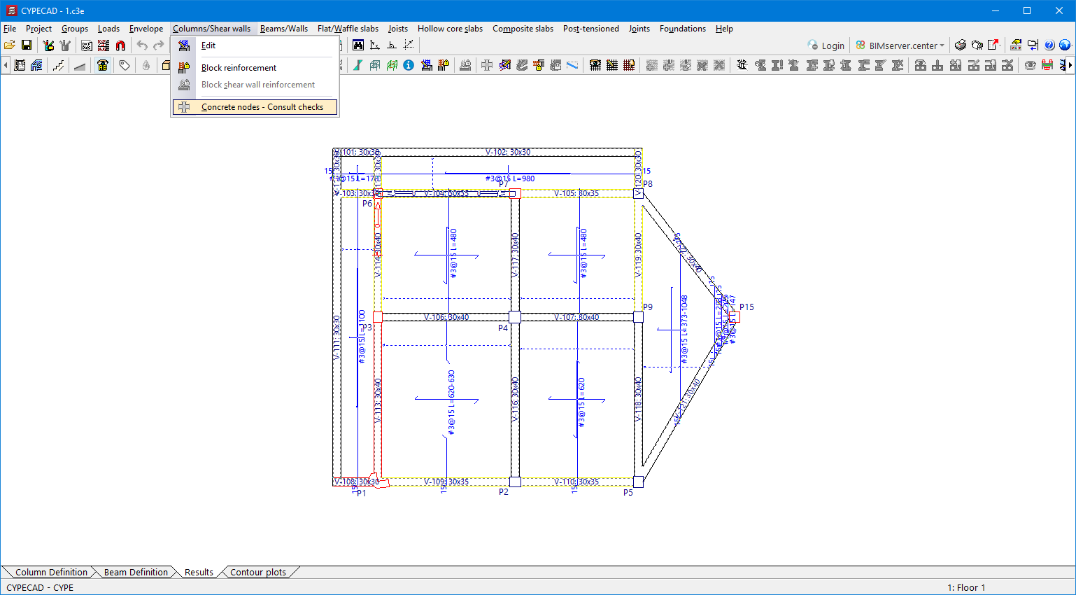
Update history​

CYPECAD

Selecting the sets of coefficients in the "Contour plots" tab

When a Eurocode has been selected in "Ground bearing pressures", it is now possible to display the values corresponding to each of the sets of coefficients according to the project approach used. The sets displayed depend on the project situations selected in the "Foundation soil" option.

"Renumber" option for columns and shear walls

With this new option, the numbering of columns and shear walls can be changed according to their position.

Users will not need to carry out another analysis in order for the new numbering to be shown on drawings and reports.

Minimum steel area of slabs in accordance with the code

The criteria for the minimum steel area of slabs for the Spanish structural code "Código Estructural" and the Eurocodes have been added.

To be applied, the "Consider the minimum reinforcement that is specified in the code" option must be selected in "Flat, waffle and joist floor slab options".

Exporting punching shear reinforcement to StruBIM Rebar

In version 2023.e, the export of punching shear rebars (reinforcement inclined at 45° and beam-type reinforcement) has been added to CYPECAD to be read by StruBIM Rebar.

Exporting portal frame reinforcement bars to StruBIM Rebar

In version 2023.e, the export of rebars is carried out per span or for the whole portal frame, depending on the assembly options selected.

  • For the "Continuous assembly reinforcement in the span - At workshop" option, the reinforcement is exported as a group by spans.
  • For the "Stirrup-carrying reinforcement" and "Continuous assembly reinforcement in the span - On site" options, the export is carried out in groups of complete portal frames.

"Divide reinforcement" option in the portal frame editor

In version 2023.e, the "Divide reinforcement" option has been added, allowing rebars to be divided at the indicated point.

Limit drift between floors due to seismic action

In version 2023.c, the limit drift between floors due to seismic action was implemented in CYPECAD by means of user-entered values.

Now, in version 2023.e, the limit drift between floors due to seismic action can be selected for several codes.

An automatic selection can be made according to one of the codes in which the drifts have been implemented, or the values can be entered manually.

An indication is given in the final report of the analysis if any of the elements do not comply with any of the selected limits.

The codes in which the limit drift between floors due to seismic action have been added in version 2023.e are:

  • EN 1998-1
    Eurocode 8: Design of structures for earthquake resistance – Part 1: General rules, seismic actions and rules for buildings.
  • ASCE 7-16
    Minimum Design Loads and Associated Criteria for Buildings and Other Structures
  • ASCE 7-10
    Minimum Design Loads for Buildings and Other Structures
  • ASCE 7-05
    Minimum Design Loads for Buildings and Other Structures
  • 2015 IBC
    International Building Code
  • 2009 IBC
    International Building Code
  • REP-2014
    Reglamento Estructural de Panamá 
  • REP-2004
    Reglamento de Diseño Estructural para la República de Panamá
  • NSR-10
    Reglamento Colombiano de Construcción Sismo Resistente (2010)
  • NCh433.Of1996 Mod.2009
    Norma Chilena Oficial. Diseño sísmico de edificios.
  • INPRES-CIRSOC 103 (2013)
    Reglamento Argentino para Construcciones Sismorresistentes. Parte I.- Construcciones en General.
  • NEC-SE-DS (2014)
    Norma Ecuatoriana de la Construcción. Peligro Sísmico. Diseño sismo resistente.
  • NEC-11
    Norma Ecuatoriana de la Construcción. Capítulo 2.- Peligro Sísmico y Requisitos de Diseño Sismo Resistente.
  • CFE-08
    Manual de Diseño de Obras Civiles. Diseño por Sismo. Comisión federal de Electricidad. México 2008.
  • CFE-15
    Manual de Diseño de Obras Civiles. Diseño por Sismo. Comisión federal de Electricidad. México 2015.
  • NTC-04
    Normas Técnicas Complementarias para Diseño por Sismo

Minor improvements and corrections

CYPECAD version 2023.d includes the following improvements and corrections of the program for certain cases:

  • Envelope > Forces in beams
    • An error that used to occur upon selecting "Envelope > Forces in beams" when one of the older concrete codes supported by the program was selected for the job has been fixed.
    • An error that occurred upon selecting "Envelope > Forces in beams" when the combinations selected by default were not active because there were no elements of that type in the current floor, has been solved. This occurred, for example, when trying to check the envelopes or combinations in a floor in which only concrete elements had been defined when, by default, the "Laminated steel" combinations were active due to the fact that these were the last combinations checked in the last job that was opened.

  • Project > General options > Limit drift between floors due to seismic action
    An error that occurred when selecting "Project > General options > Limit drift between floors due to seismic action" if the job had no seismic code activated has been fixed.

  • Changing column material
    An error that occurred when changing the material of a circular column from steel to timber has been fixed.

  • “Drift between floors due to seismic action” report
    • The "Drift between floors due to seismic action" report has been improved when considering the second-order effects of seismic action.
    • An error that occurred in the "Drift between floors due to seismic action" report when selecting "Interaction with the structure" in "General data > Building elements" has been fixed.

Graphical editing of the reference system of the model

Since version 2022.a, the applications integrated within the Open BIM workflow via the BIMserver.center platform include a tool for managing project reference systems. This option is available from the configuration window that appears when linking or updating a BIMserver.center project via the "Geographic location and reference system" option. As of version 2023.d, the applications now allow users to run a graphical environment where they can visually define a reference system for their model. To do this, the "Geographic location and reference system" window now contains the "Visual editing of the local reference system of the model" option.

From the "Visual editing of the local reference system of the model" window, the origin and orientation of the reference system of the model can be indicated in the workspace with the "Define the reference system of the partial model" tool. Both the axes of the reference system of the model, which we have just entered and the axes of the reference system of the site can be viewed in the workspace. The latter appears with a "Site" tag.

To make it easier to define the reference system, the 3D models corresponding to the BIMserver.center project contributions selected during the linking process are displayed. The management of the visibility and object snaps of these models is carried out from the "Elements read" menu in the left sidebar of the window. The "Views" menu can also be found in the same options bar, from which different types of 2D and 3D views of the model can be generated. These tools can already be found in several CYPE applications. For more information on how they work, please refer to the User’s Manual for the 3D work environment tools available in CYPE applications.

Apart from 3D models, 2D drawings or plans can also be imported from CAD files (".dxf", ".dwg", ".dwf") or images (".jpeg", ".jpg", ".bmp", ".png", ".wmf", ".emf", ".pcx"). These files and object snaps are managed through the "DXF-DWG Template" and "Template object snaps" options accordingly.

Once the editing is complete, the coordinates and orientation of the reference system of the model with respect to the reference system of the site are moved to the corresponding fields in the "Geographic location and reference system" window.

Font size

The "Font size" option has been added to the general configuration menu of the applications. This tool allows users to increase or decrease the basic size of the font used in the user interface of the programs. Thanks to this implementation, the accessibility of the applications has been improved while also ensuring the correct visibility of the content on devices with different screen resolutions.

To enter a "Basic size" the "Set custom font size" option must be checked. The size users can enter is the application's basic font size. Any other font sizes that may exist in the program's interface will be automatically modified proportionally according to the change in the basic size.

It is important to note that, as this is a common parameter, its modification will affect all installed CYPE tools.

CYPECAD "Health and safety" tab

As of version 2023.c, CYPECAD no longer includes the "Health and safety" tab. The features of this CYPECAD tool for drawing up plans of collective protection elements are largely superseded by the "CYPE Health and safety" program.

CYPE Health and safety can be downloaded from the BIMserver.center platform and, ever since this application was implemented in version 2019.a, the permissions that allow its use are the same as those that provide access to the CYPECAD "Health and safety" tab.

Installation in Polish

As of version 2023.c CYPECAD can also be installed in Polish.