Export detailing of the steel structure (IFC EM.11) (StruBIM Steel module)
In version 2023.e, the "Export in IFC EM.11 format" module has been added for StruBIM Steel.
With this module, StruBIM Steel can export an IFC with the information required for automated structural steel fabrication.
More information on this module can be found in the StruBIM Steel new feature from this 2023.e version: "Export in IFC EM.11 format (new module)".
Buckling analysis (local stability) (StruBIM Steel and CYPE Connect module)
In version 2023.e, the "Buckling Analysis (local stability)" module has been added, allowing StruBIM Steel and CYPE Connect to perform the local buckling analysis of connections.
More information on this module is available in this version's new feature: "Buckling Analysis (local stability) (new module)" common to StruBIM Steel and CYPE Connect.
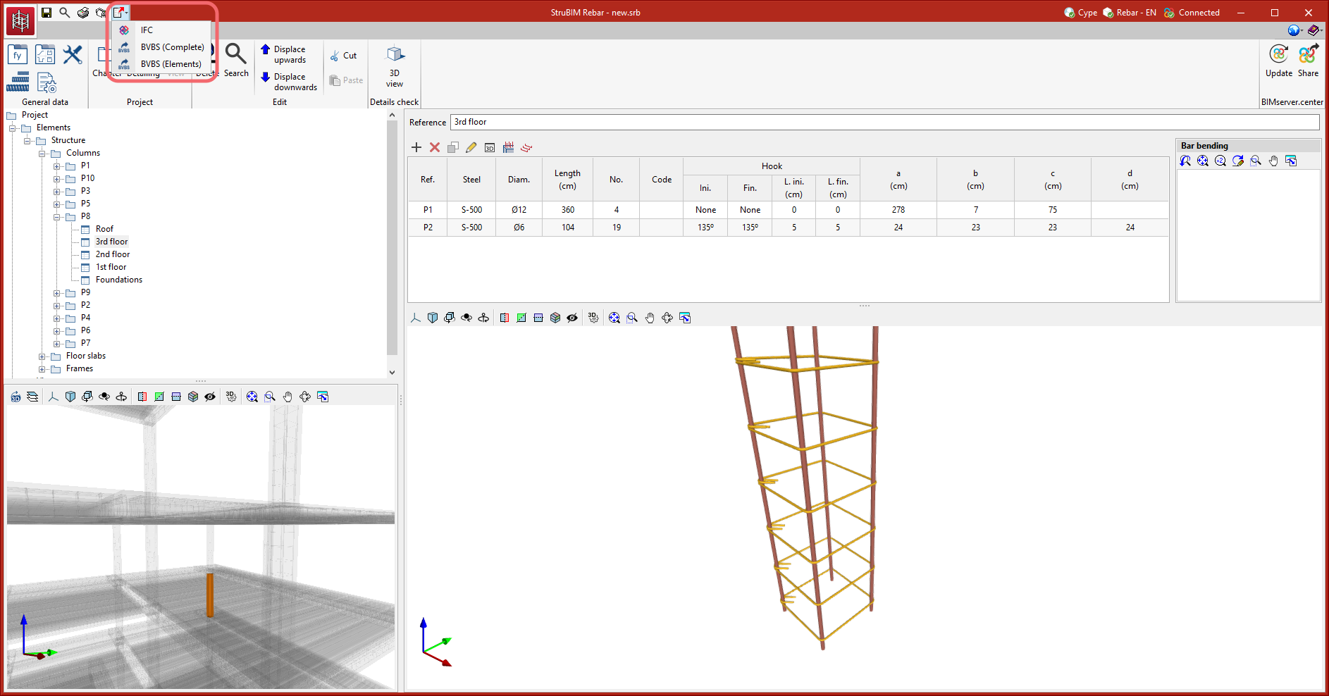
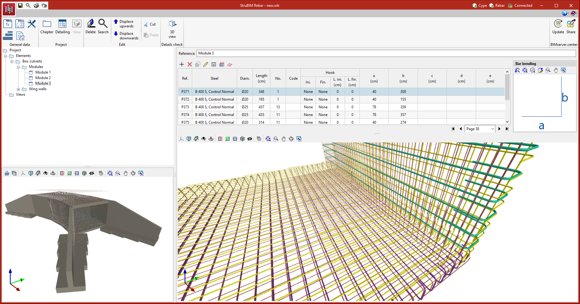
Export reinforcement detailing (IFC and BVBS) (StruBIM Rebar module)
In version 2023.e the "Export reinforcement detailing (IFC and BVBS)" module has been added, allowing StruBIM Rebar to export accurate rebar information to the BIM model in order for it to be fabricated.
More information on this module is available in StruBIM Rebar's new feature: "Export reinforcement detailing (IFC and BVBS) (StruBIM Rebar module)".
Dockable windows
As of version 2023.e, some CYPE applications have a new dockable window system that replaces the main screen user interface. As a result, users can now customise the workspace to suit their needs.
The list of applications that have this dockable window system appears at the end of this new feature. In future versions, the number of applications with this window system will be increased.
Dockable windows can be moved and resized. They can be either floating windows, pinned to a location within the application's main dialogue box, dragged outside of it, or even moved to another monitor.
- Move windows
A docked window can be moved by clicking on the title bar at the top of the window and dragging it.
When dragging a dockable window, several visual aids are displayed to make its relocation easier. Next to the cursor, a text box appears containing the title of the dockable window being moved. Whenever the cursor approaches the edge of another window, a box appears showing a preview of the space it would occupy.
It is possible to leave a window as a floating window without docking it to another window, and it is also possible to dock windows within a floating window. Holding down the CTRL key can prevent a floating window from being docked while it is being moved.
- Group windows
It is possible to group several windows in the same space by dragging one window to the top left-hand corner or to the bottom left-hand corner of another window. When this is carried out, tabs will appear at the bottom or top of the group, allowing users to alternate between the grouped windows. If the tabs are at the bottom, the title of the group of windows corresponds to the active window. On the other hand, if the tabs are at the top, they will be used as the title.
- Show/Hide windows
The icon to close the window can be found in the top right-hand corner of each dockable window.
To manage the display of the dockable windows in the user interface, a "Window" button ( ) has been added to the application environment, next to the "General Settings" button (icons on the top right-hand side of the program). By clicking on it, a drop-down menu appears with the available dockable windows and users are able to change their status. In addition, there is the "Reset Window Layout" option which allows users to restore the default workspace.
In some cases, such as the "Work area" of applications with a 3D environment, the window cannot be hidden. In these cases, the icon for closing the window is not displayed and, in the "Window" menu (), the "Work area" will be locked.
- Collapse windows
When several dockable windows are arranged vertically, an icon is displayed, next to the close icon, which allows each window to be expanded or collapsed. When the window is collapsed, it will return to its previous size.
The window layout and display settings are saved when closing the application.
It is important to note that not all floating windows in an application are dockable windows. In order to tell them apart, the ![]() icon has been added to the title bar of windows that are dockable.
icon has been added to the title bar of windows that are dockable.
The following applications now include the new floating window environment in version 2023.e:
- AcouBAT by CYPE
- CYPE Architecture
- CYPE Connect
- CYPEFIRE
- CYPEHVAC 3D
- CYPEPLUMBING Water Systems
- CYPESOUND
- CYPETHERM LOADS
- Open BIM Analytical Model
- CYPE Construction Systems
- Open BIM COVID-19
- Open BIM Layout
- CYPE Lightning
- Open BIM Quantities
- Open BIM Site
- StruBIM Steel
- The floating window environment also includes the "Bill of Quantities" tab in all applications that have this tab.
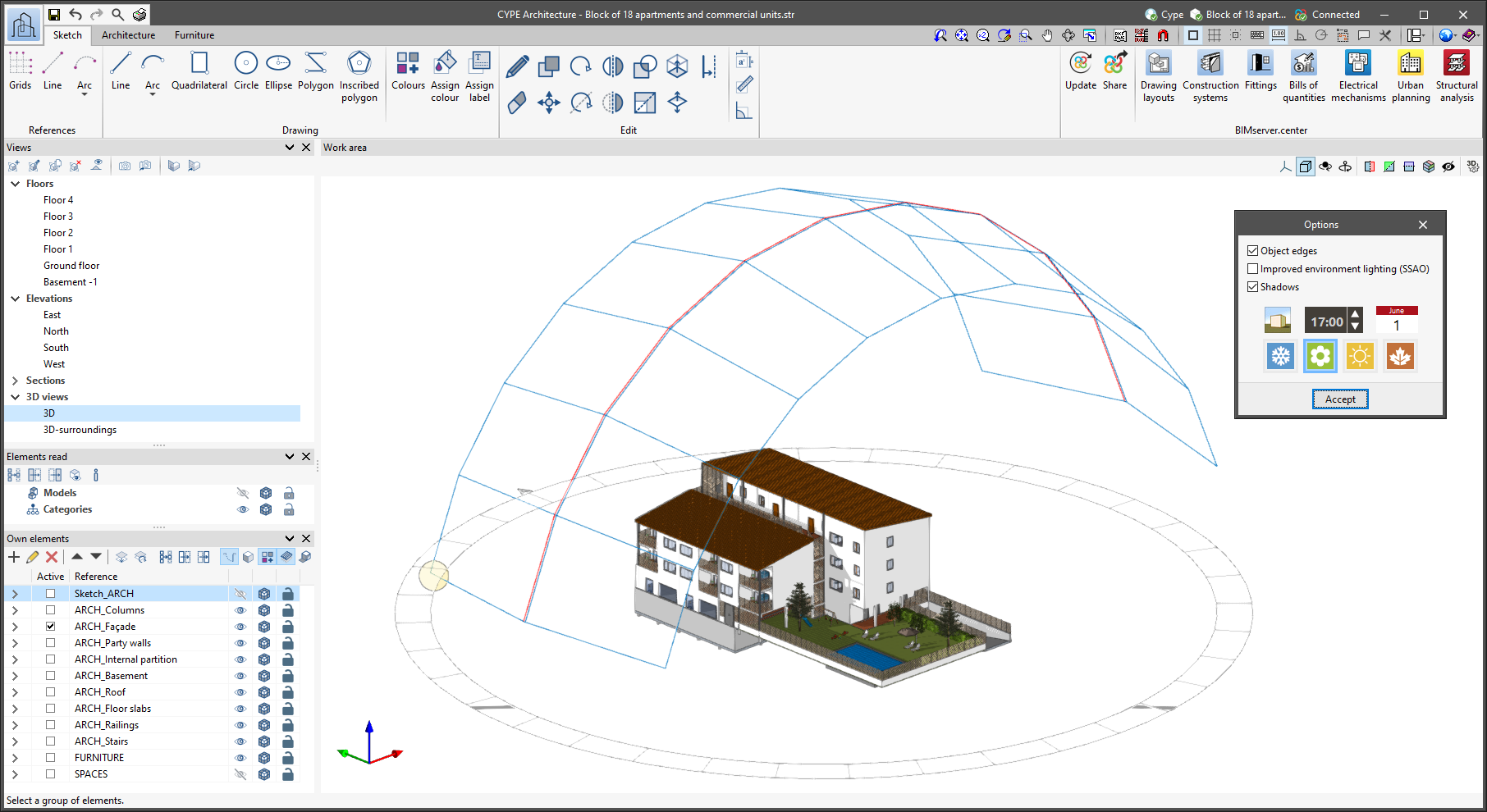
Shadow display
In the 3D view of the application, the model's own shadows can be displayed as well as the shadows cast by adjacent buildings.
Users can choose the solar time for any day of the year on which they wish the shadows to be reproduced, as well as display the sun's position and trajectory.
This new feature is available via the "Options" group of the 3D view in the top right bar of the work area.
The location of the job must be specified by indicating its latitude and north in the "Own elements" window of the "Shadows" option.
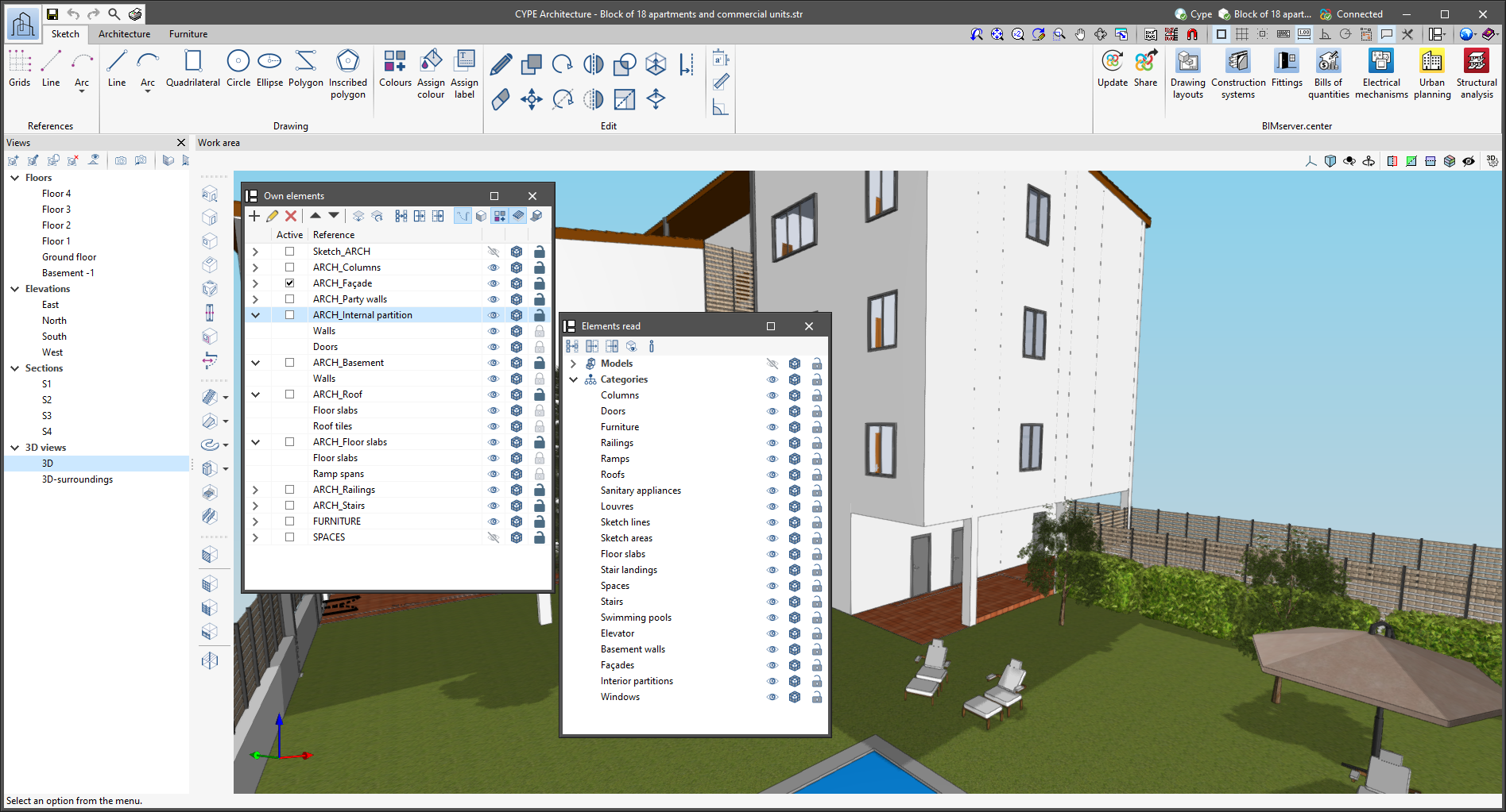
Improved display of own elements
The categories that exist within each of the layers can be displayed. In addition, the categories within each layer can be switched on and off, the display mode can be changed (normal, transparent and wire) and it can be locked.
To display the categories of a layer, simply expand the layer.

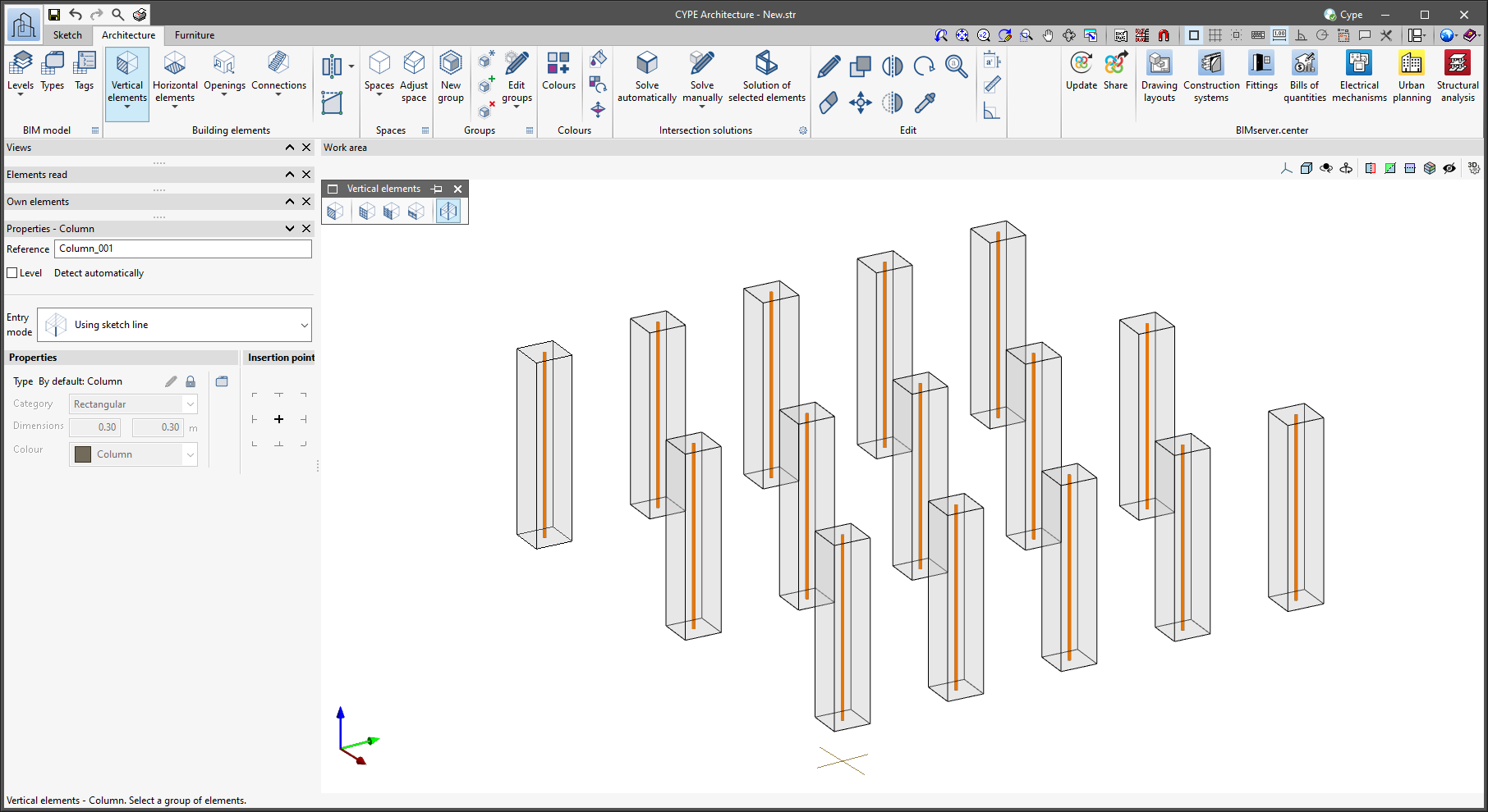
Multiple selection for tools using generation by surface area or using a sketch line
The program allows multiple surface areas or sketch lines to be selected and converted into specific building elements. This increases the drawing speed.
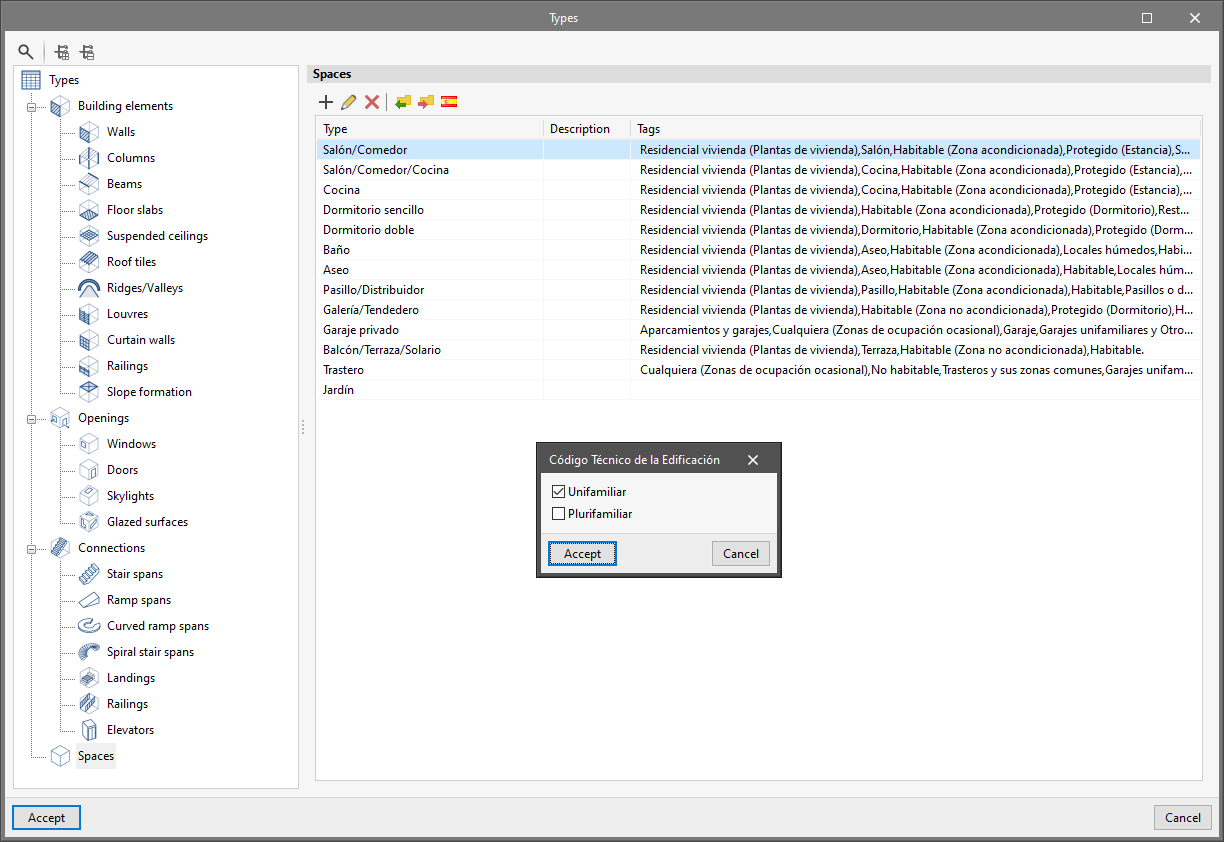
Wizard for space types
The program has a wizard that allows users to load space types according to the use of the building. In the first version of this wizard, there are space types for single-family and multi-family dwellings. The space types in the wizard contain the necessary tag information to be read in other programs from the Open BIM workflow.
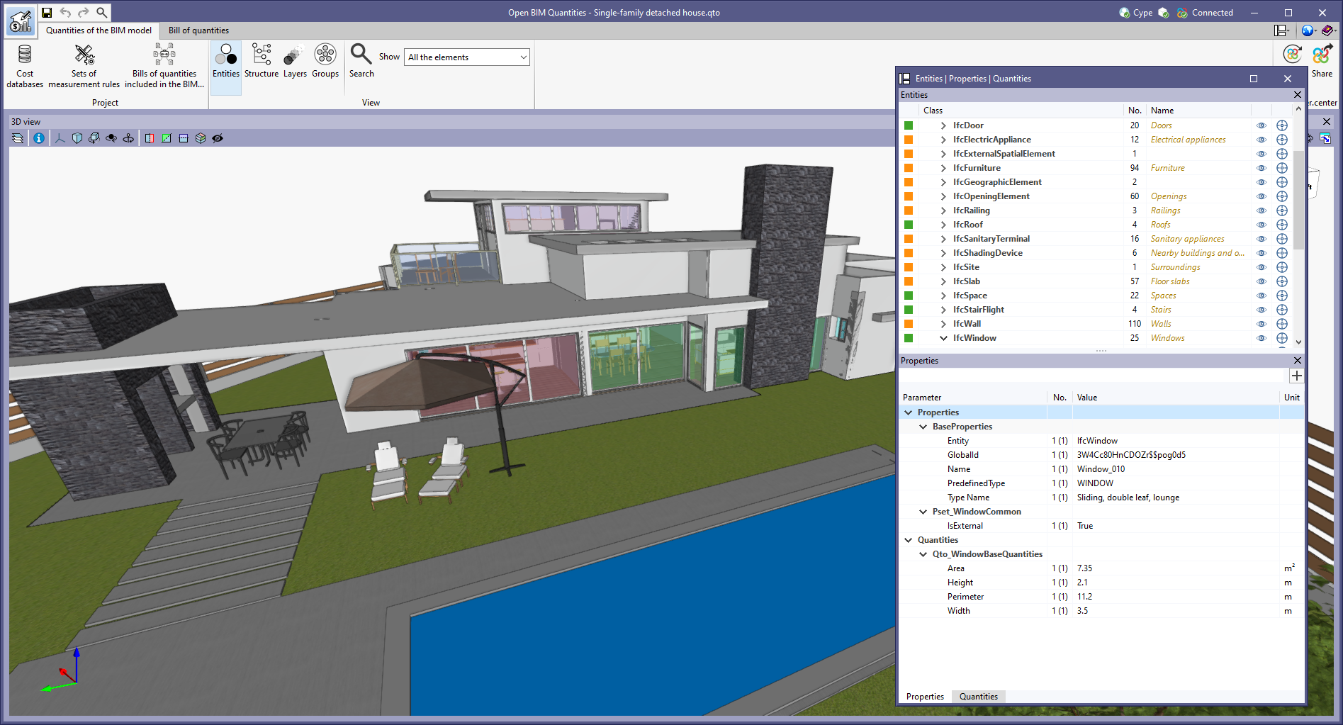
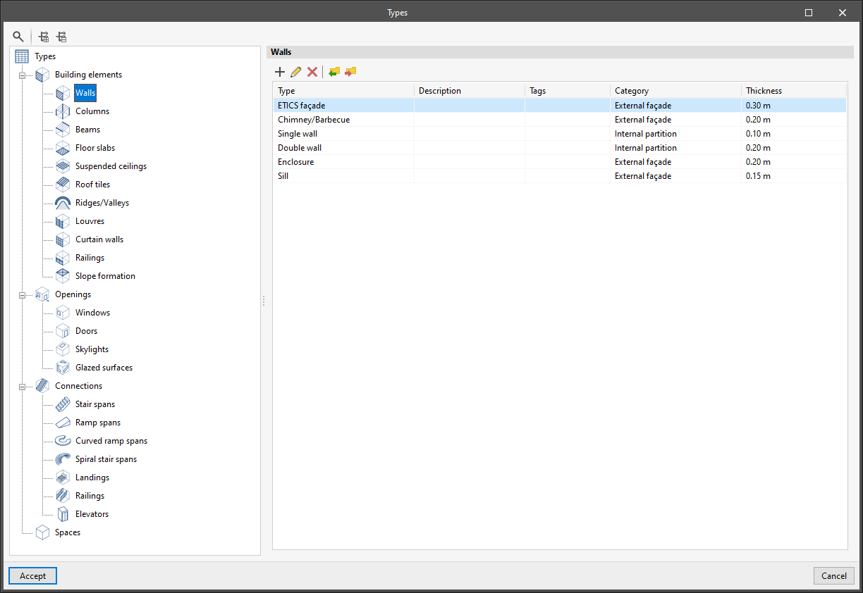
Improved Types and BIM Model windows
A new display of the "Types" and "BIM Model" windows has been implemented by means of a tree structure of the elements.
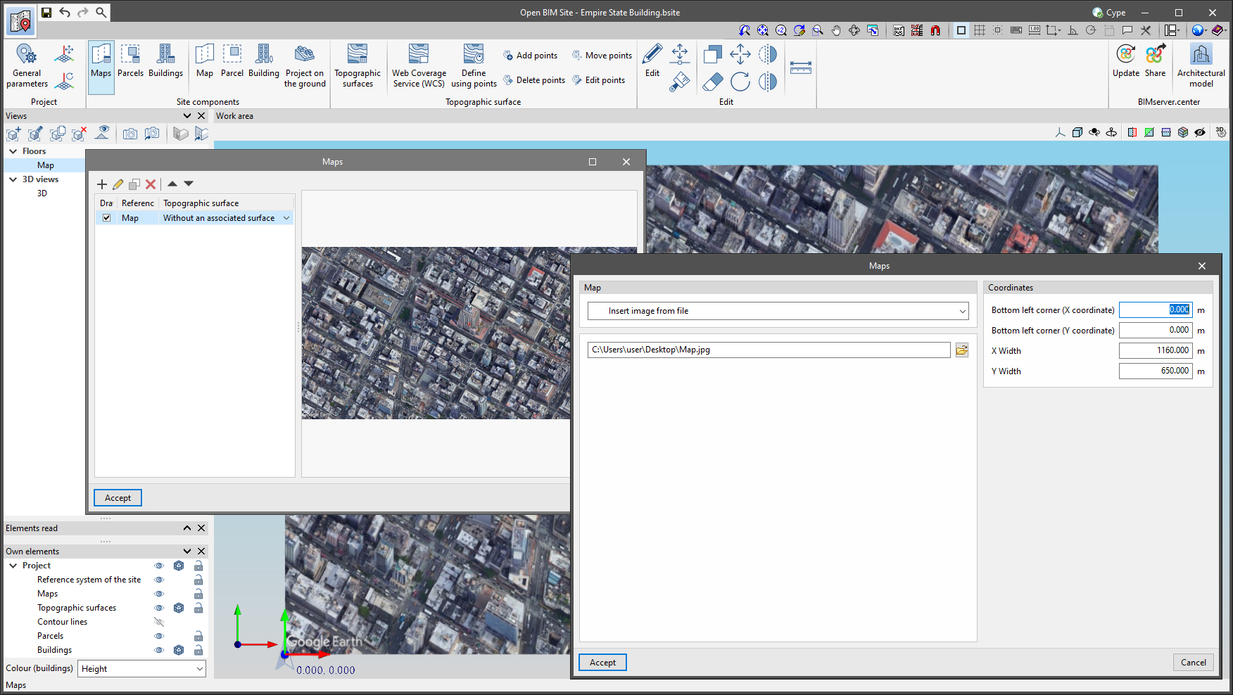
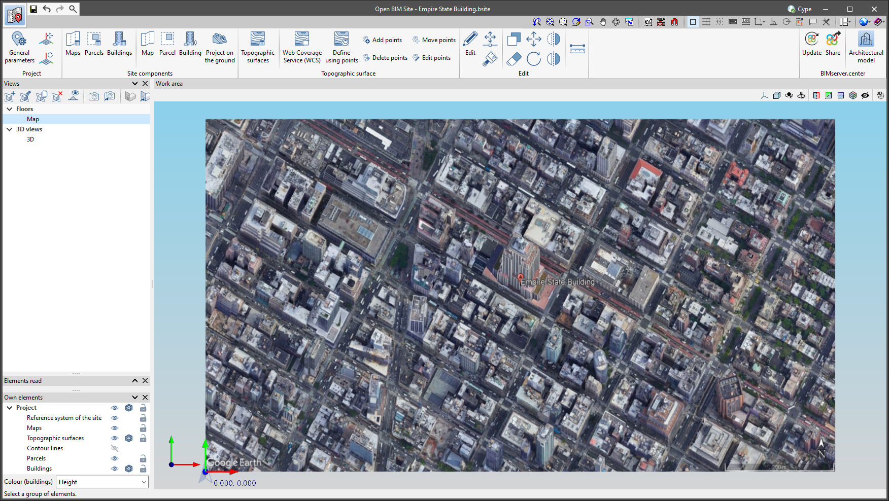
Entering maps from image files
Up until now, maps of Open BIM Site projects had to either be obtained from one of the WMS services connected to the application or, if a file was available, the template system had to be used. As of version 2023.e, Open BIM Site allows maps to be imported directly from image files. To do this, the "Insert image from file" option has been added in the properties window of a map. When selecting it, the complete path of the image must be specified. The format of the image can be JPEG (".jpeg", ".jpg"), BMP (".bmp"), PNG (".png") or WMF (".wmf"). Additionally, as with the rest of the maps, users must specify the coordinates where the image will be inserted and the actual size of the image.
The main advantage of using the application maps over the template system of the drawing environment is that the maps can be projected onto the topographic surfaces and then exported to the BIMserver.center project.
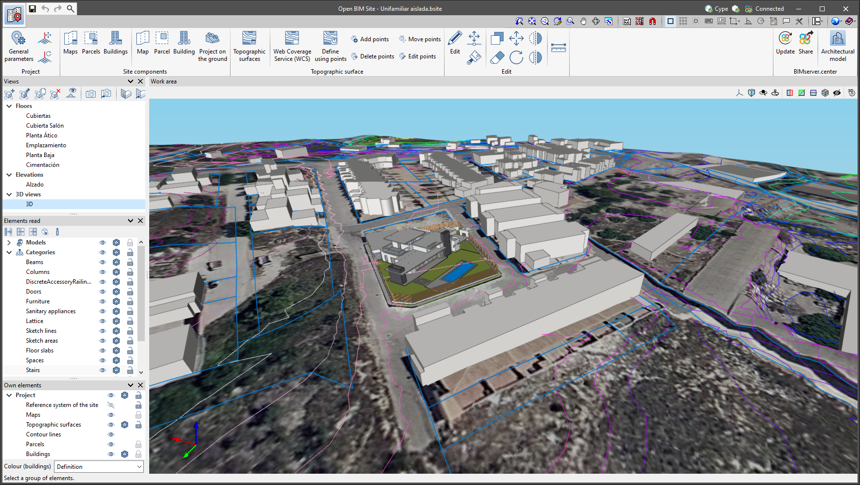
Updated example jobs
The Spanish example job "Unifamiliar aislada" has been updated.
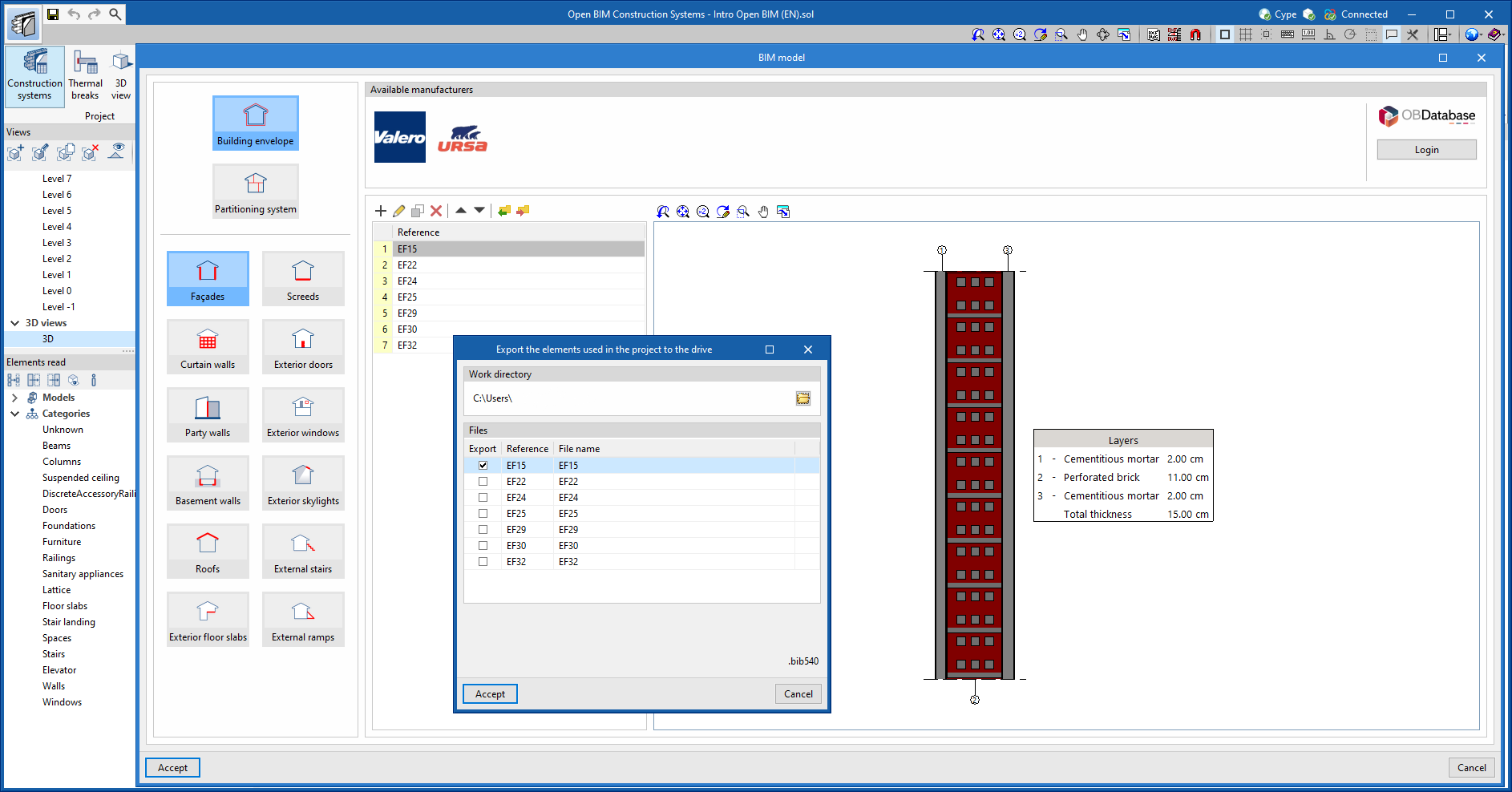
Importing and exporting a list of construction systems
As of version 2023.e, CYPE Construction Systems allows users to import and export several construction solutions simultaneously from the element list of a category (façades, screeds, curtain walls, etc.).
This way, users don't need to carry out the process for each construction solution individually, thus making it easier to reuse the same systems in several projects.
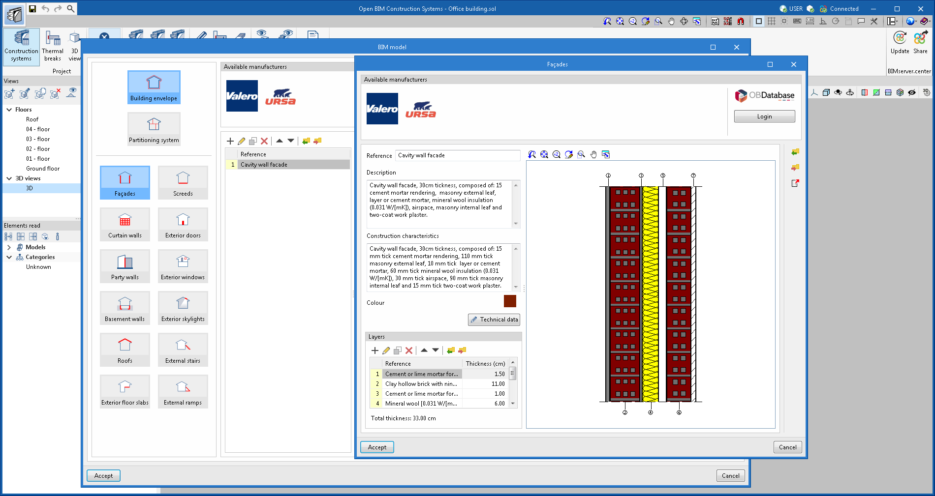
Calculating the total thickness of a construction system defined by layers
In the window for defining a construction solution by layers (façades, partitions, floor slabs, roofs, etc.) a new field has been added with the value of the total thickness. This is calculated dynamically according to the individual thicknesses of the layers.
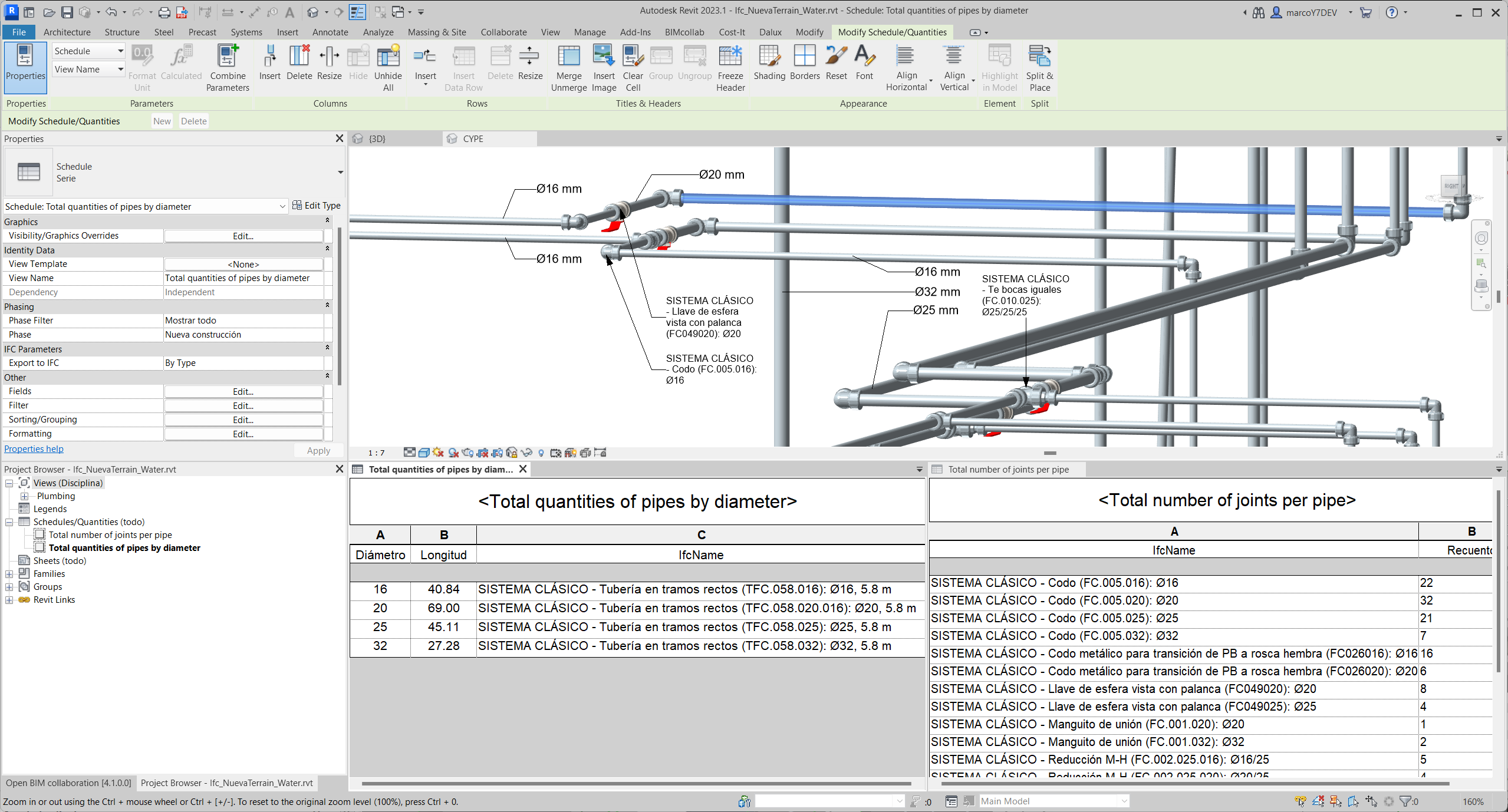
IFC options
In version 2017.f, an add-on or plugin was included for AutoDesk© Revit software that makes it easier to include Revit in the Open BIM workflow. Since then, this plugin aims to improve communication between Revit and the BIMserver.center platform, where CYPE's specialised tools are located.
Version 2023.e is a significant improvement in terms of the ability to manage the information contained in the IFC files used for model exchange. A revision of the CYPE software suite has been carried out to improve the quality of the information and classification of the objects contained in the IFC models. This information is provided by the plugin and its new mapper from IFC classes to Revit Categories. This mapper is contained in the new "IFC options" feature. "IFC Options" allows users to overwrite the import/export options set in the Revit configuration. In addition to overcoming several recognition limits of IFC classes and types, it allows object conversion to and from IFC to be customised and optimised. This optimises the BIM workflow of projects modelled in Revit and analysed with CYPE software, and focuses on the possible detailing models generated from the applications belonging to the manufacturer's systems.

The information in the linked IFC file, contained in recognisable elements belonging to Revit's own categories, is made available to the Revit user and allows tagging or listing actions to be carried out in planning tables.
Create tag based on an existing tag
This new tool allows users to create the same type of tag with the same content as the tag selected on the sheet. To do this, once the tool has been selected, users must select the tag they wish to copy and then the element to which they wish to assign the tag.

Copy the contents of a tag
This new tool allows content to be copied between the same type of tags. The content includes the variables of the tag.
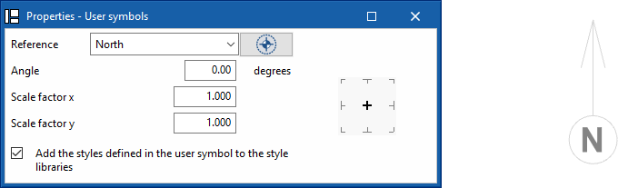
Scale factor for user symbols
User symbols can be entered on a different scale than the one on which they were created. The scale can be defined on the "X" and "Y" axes of the symbol.
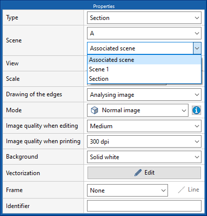
Use the section defined in one scene to create a section in another scene
The program allows users to draw a section based on a particular scene, and then associate the same section plane to a different scene.
Limit drift between floors due to seismic action
In version 2023.c, the limit drift between floors due to seismic action was implemented in CYPECAD by means of user-entered values.
Now, in version 2023.e, the limit drift between floors due to seismic action can be selected for several codes.
An automatic selection can be made according to one of the codes in which the drifts have been implemented, or the values can be entered manually.
An indication is given in the final report of the analysis if any of the elements do not comply with any of the selected limits.
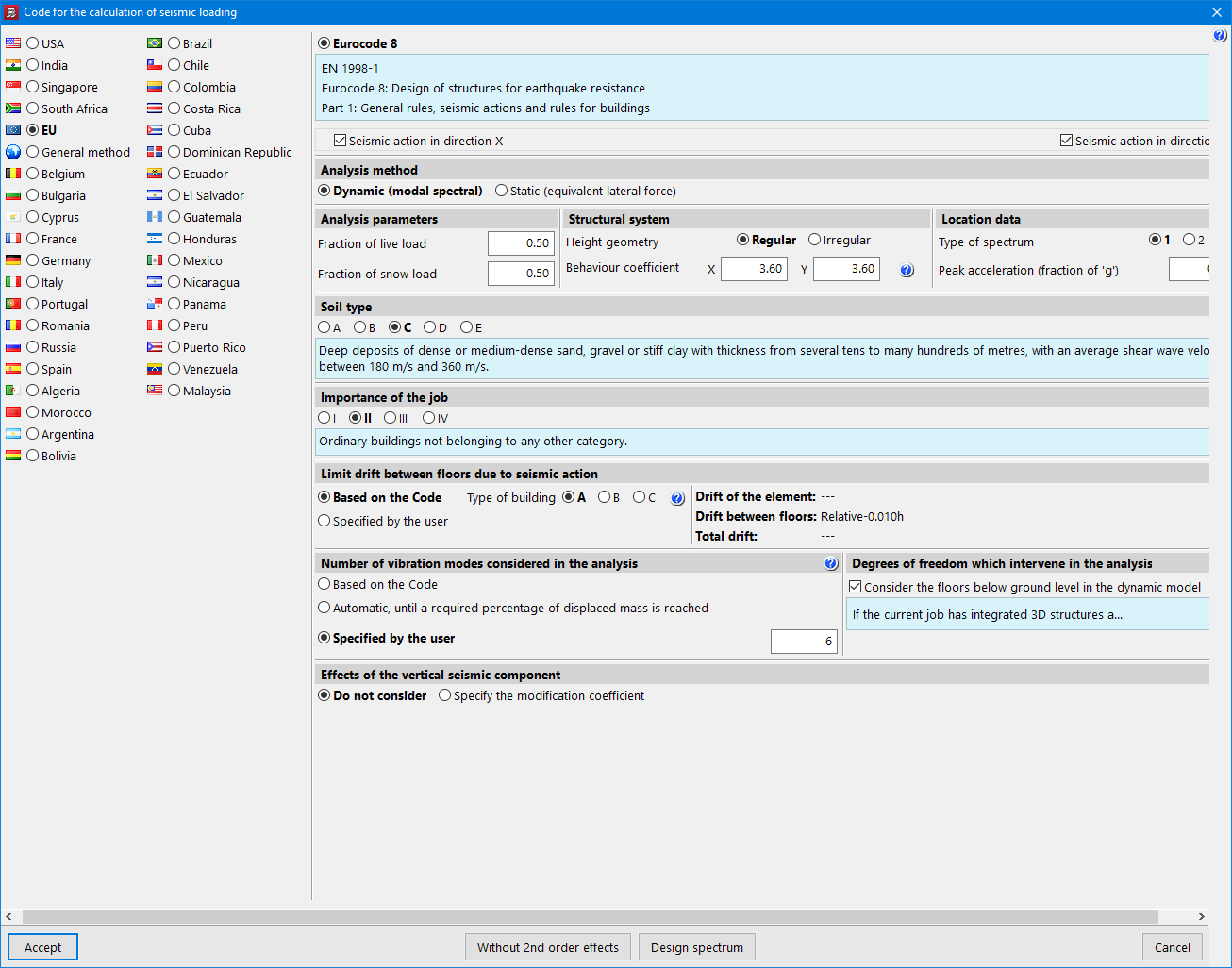
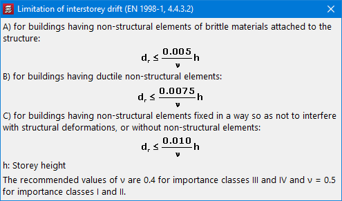
The codes in which the limit drift between floors due to seismic action have been added in version 2023.e are:
- EN 1998-1
Eurocode 8: Design of structures for earthquake resistance – Part 1: General rules, seismic actions and rules for buildings. - ASCE 7-16
Minimum Design Loads and Associated Criteria for Buildings and Other Structures - ASCE 7-10
Minimum Design Loads for Buildings and Other Structures - ASCE 7-05
Minimum Design Loads for Buildings and Other Structures - 2015 IBC
International Building Code - 2009 IBC
International Building Code - REP-2014
Reglamento Estructural de Panamá - REP-2004
Reglamento de Diseño Estructural para la República de Panamá - NSR-10
Reglamento Colombiano de Construcción Sismo Resistente (2010) - NCh433.Of1996 Mod.2009
Norma Chilena Oficial. Diseño sísmico de edificios. - INPRES-CIRSOC 103 (2013)
Reglamento Argentino para Construcciones Sismorresistentes. Parte I.- Construcciones en General. - NEC-SE-DS (2014)
Norma Ecuatoriana de la Construcción. Peligro Sísmico. Diseño sismo resistente. - NEC-11
Norma Ecuatoriana de la Construcción. Capítulo 2.- Peligro Sísmico y Requisitos de Diseño Sismo Resistente. - CFE-08
Manual de Diseño de Obras Civiles. Diseño por Sismo. Comisión federal de Electricidad. México 2008. - CFE-15
Manual de Diseño de Obras Civiles. Diseño por Sismo. Comisión federal de Electricidad. México 2015. - NTC-04
Normas Técnicas Complementarias para Diseño por Sismo
"Divide reinforcement" option in the portal frame editor
In version 2023.e, the "Divide reinforcement" option has been added, allowing rebars to be divided at the indicated point.
Exporting portal frame reinforcement bars to StruBIM Rebar
In version 2023.e, the export of rebars is carried out per span or for the whole portal frame, depending on the assembly options selected.
- For the "Continuous assembly reinforcement in the span - At workshop" option, the reinforcement is exported as a group by spans.
- For the "Stirrup-carrying reinforcement" and "Continuous assembly reinforcement in the span - On site" options, the export is carried out in groups of complete portal frames.
Exporting punching shear reinforcement to StruBIM Rebar
In version 2023.e, the export of punching shear rebars (reinforcement inclined at 45° and beam-type reinforcement) has been added to CYPECAD to be read by StruBIM Rebar.
Minimum steel area of slabs in accordance with the code
The criteria for the minimum steel area of slabs for the Spanish structural code "Código Estructural" and the Eurocodes have been added.
To be applied, the "Consider the minimum reinforcement that is specified in the code" option must be selected in "Flat, waffle and joist floor slab options".
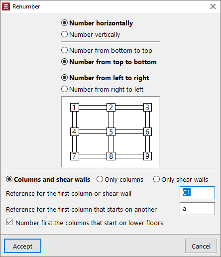
"Renumber" option for columns and shear walls
With this new option, the numbering of columns and shear walls can be changed according to their position.
Users will not need to carry out another analysis in order for the new numbering to be shown on drawings and reports.
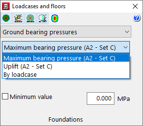
Selecting the sets of coefficients in the "Contour plots" tab
When a Eurocode has been selected in "Ground bearing pressures", it is now possible to display the values corresponding to each of the sets of coefficients according to the project approach used. The sets displayed depend on the project situations selected in the "Foundation soil" option.
Other improvements and corrections
CYPECAD version 2023.e includes the following program improvements and corrections for some specific cases:
- The export of rebars from portal frames has been improved. The type of bend selected in the assembly reinforcement is now considered.
- The editing data feature associated with the seismic code in the "General data" panel after cancelling the editing of seismic code data has been improved.
- The export of coupling beams has been improved. If two beams start at the same wall and end at the same wall an error occurred when importing them into the StruBIM Shear Walls program.
- The export of column rebars has been improved. In some cases, when bends need to be carried out, they were generated with an inadequate bending distance.
- The "Draw the DXF/DWG template" option available in the "Floor plans" configuration has been improved. Sometimes it had no effect on the output of the drawings.
- An error that could occur when selecting a pile has been fixed. This could happen after deleting a pile from the library that was being used in a pile cap.
- The use of hollow core slabs has been improved. Previously, users could not select a hollow core slab from the library with a reinforcement whose steel was different from the one defined in the job. It is now possible to select hollow core slabs that have been defined with a steel quality lower than the one selected in the job.
- An error that occurred very rarely when generating the ridge beam analysis model has been fixed.
- As of version 2023.e, the maximum number of floors per group has been changed from 5 to 10.
- An error in the design of wall openings that could occur if the opening was located on a floor marked with continuous reinforcement has been fixed.
- An error that occurred sometimes when opening a job where a wall had previously been moved has been fixed.
- The export of basement walls to the IFC format has been improved. If the thickness of the wall varied from one floor to another, this was not considered and was always exported with the thickness of the floor below.
- User concrete library
The lower range of the characteristic compressive strength of concrete has been changed to 4 MPa and that of the modulus of elasticity of concrete design to 5000 MPa. - An error that occurred when designing a job where there were timber bars defined in an integrated 3D structure with a timber type that had been removed from the library, has been fixed.
- The inclusion of connections of 3D structures added to the design model has been improved in cases where they are situated near the intersection of two beams. Sometimes, depending on the order in which these beams were entered, an additional node was generated, which could cause an unjustified jump in the torsion diagram.
- An error that occurred in a customised report if the "Beam reinforcement report" chapter was included together with the "U.L.S. Checks" chapter has been fixed.
- An error that occurred in some circumstances when checking the torsion in a portal frame if BS 8110-1:1997 was the selected standard has been fixed.
- The generation of the interchange file has been improved. Now stirrup intervals are no longer divided if a span has intermediate connections.
- The "Wet Service Factor" has been changed from 1 to 0.85 for the Argentinean timber standard CIRSOC.
Buckling analysis (local stability) (new module)
As of version 2023.e, users can now analyse the local buckling of joints in CYPE Connect and StruBIM Steel. This new type of analysis is added to those already existing in previous versions: Stress/Strain and Rotational Stiffness.
The local buckling analysis of joints in CYPE Connect and StruBIM Steel is part of the "Buckling analysis (local stability)" module (a module common to both programs). In order to carry out this analysis, users must have the required permissions for the aforementioned module in their user license.
The local buckling of a joint component occurs due to compression forces and depends, to a large extent, on the stiffness of the component and the distribution of the applied loads. A buckling analysis helps to detect the unstable configurations of a joint design under the action of a given load case, in other words, it helps to prevent unsafe designs.
There are several ways to evaluate the buckling phenomenon using finite elements. The one implemented in the analysis of joints is the "linear buckling analysis" which allows users to obtain the critical load factors of the different local buckling modes of the joint for a given load case. The smaller the first critical load factor, the closer we will be to an unstable joint configuration.
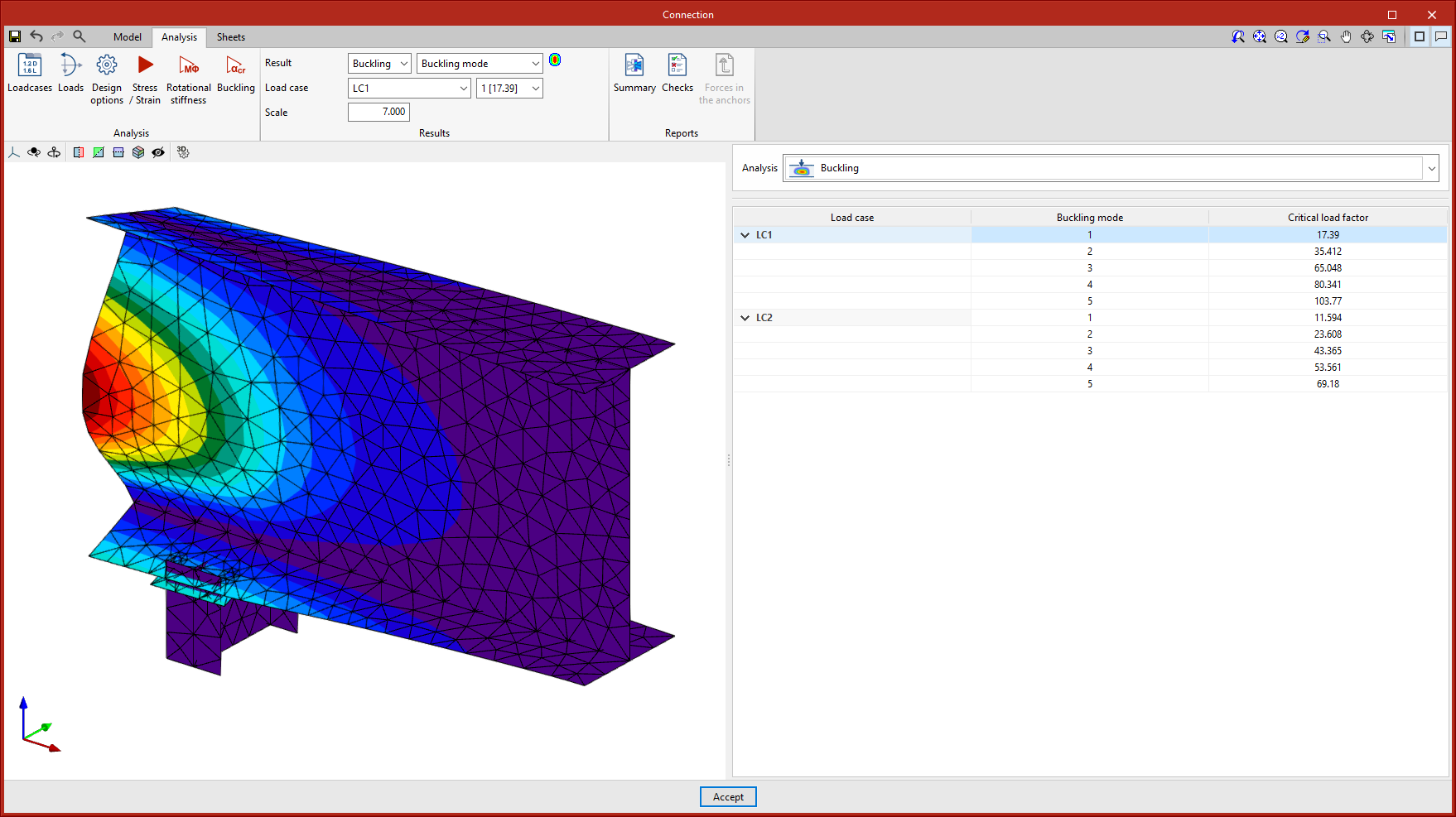
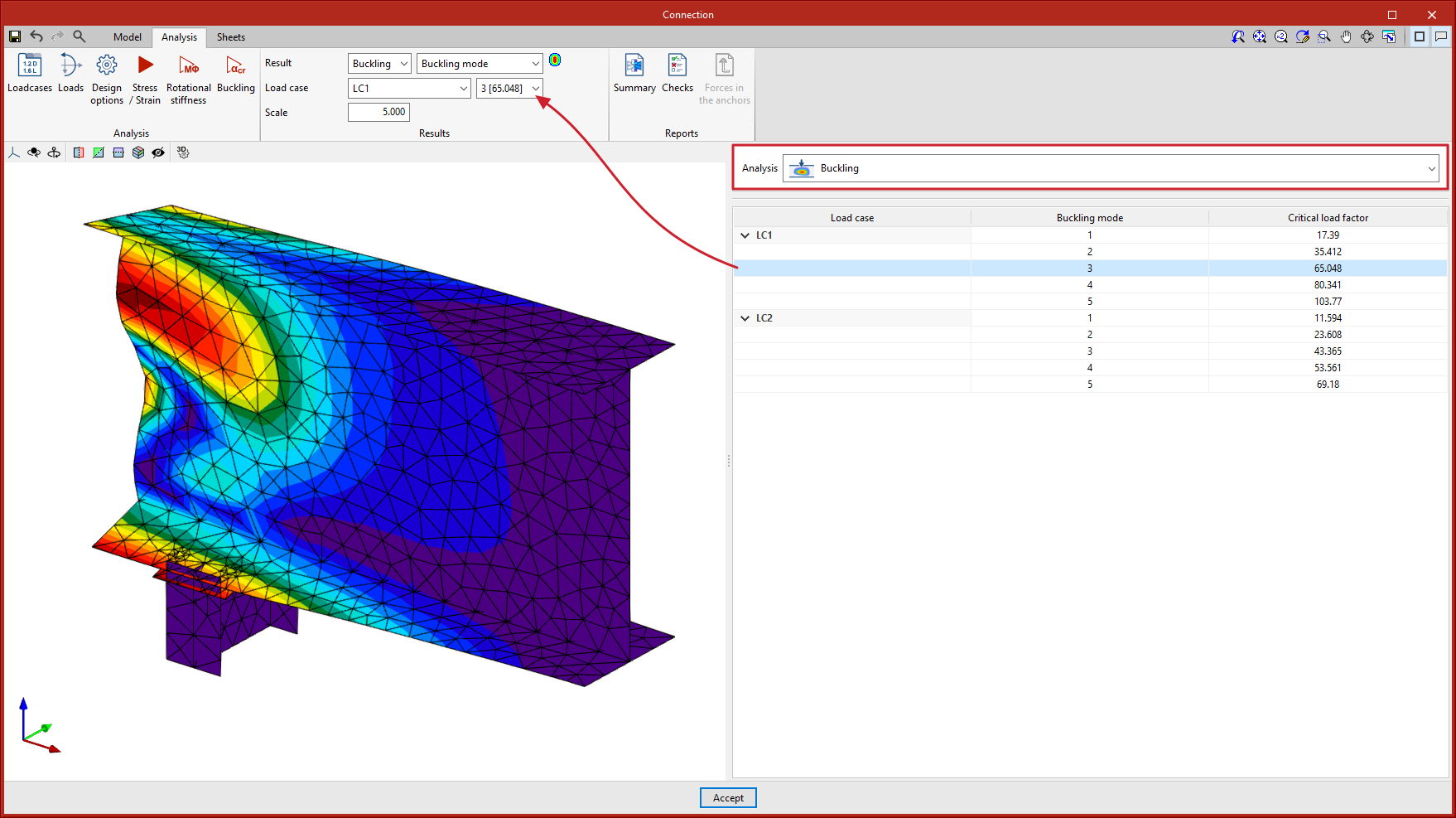
A new option for carrying out the buckling analysis has been added to the top options bar in the "Analysis" tab.
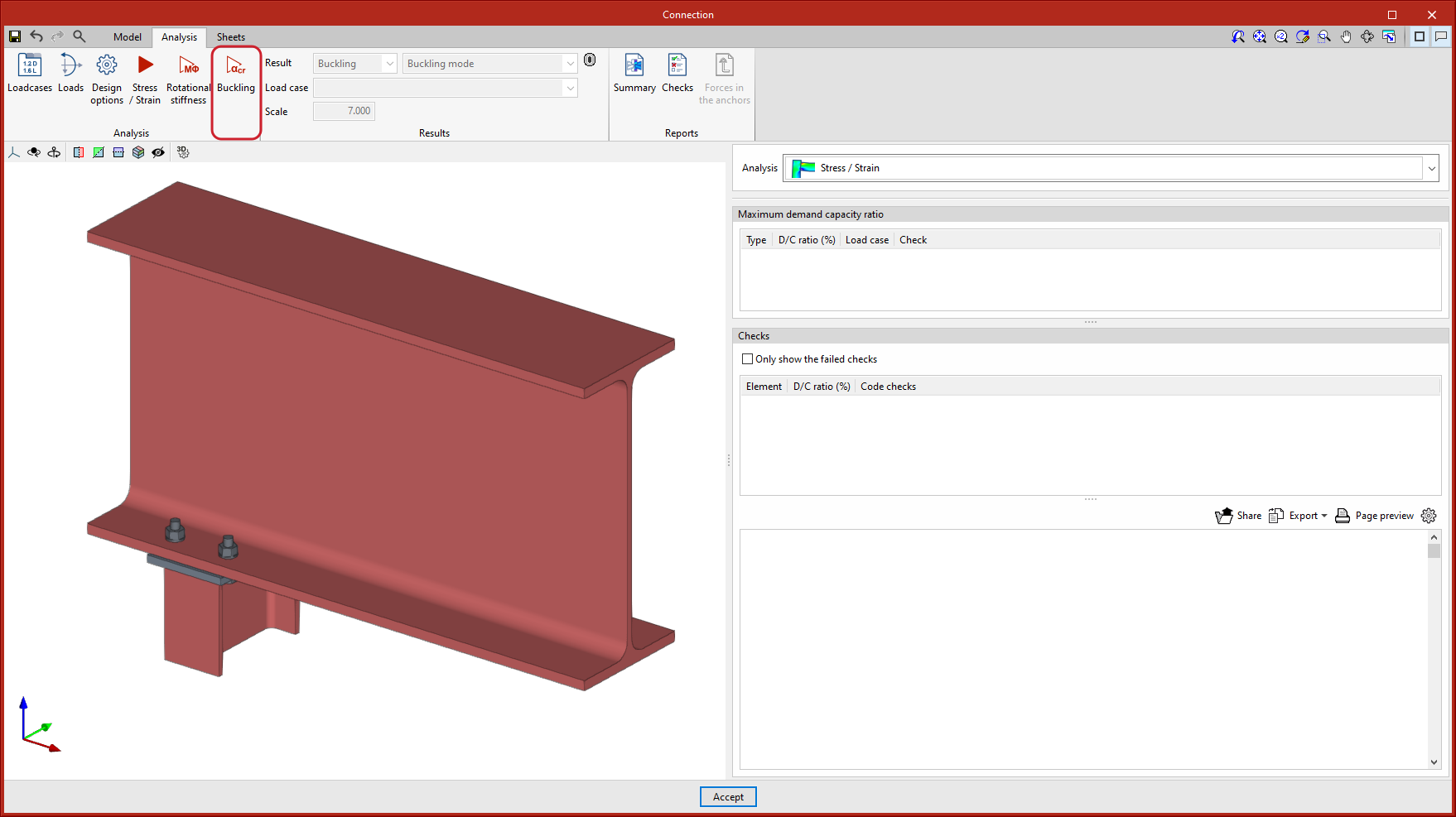
Once the analysis has been completed, the critical load factors for each of the buckling modes and their deformed shape will be obtained as a result.
By selecting the "Buckling" option in the drop-down menu of the results sidebar, a table will be displayed with the buckling modes of each load case and their corresponding critical load factors. Clicking on each mode will display the corresponding deformed shape.
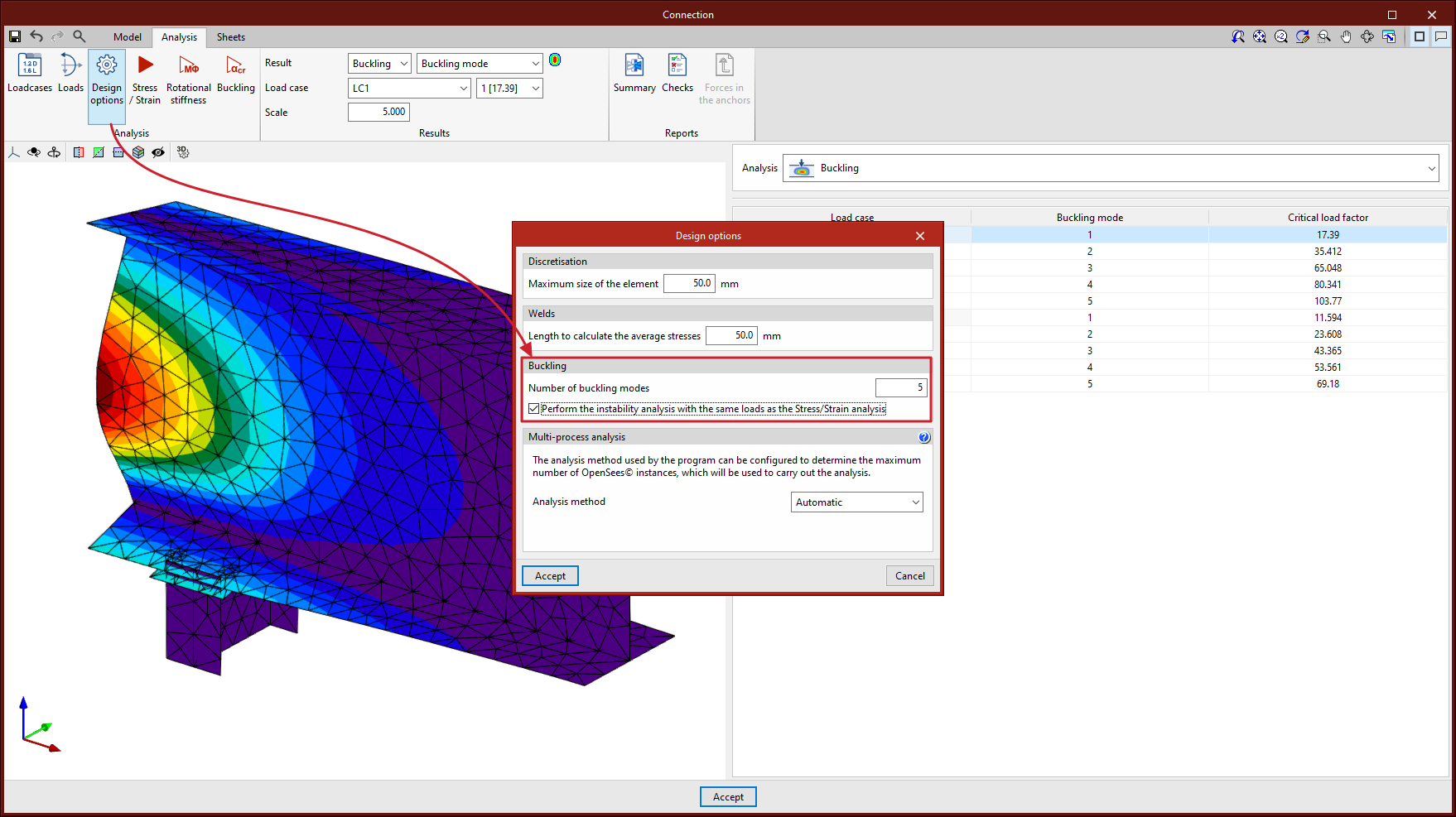
In "Analysis options" the number of buckling modes to be analysed can be selected. The buckling analysis can be performed with the same loads as the "Stress/strain" analysis or with a different set of loads. This can be controlled by checking or unchecking the "Perform the instability analysis with the same loads as the Stress/Strain analysis" option.
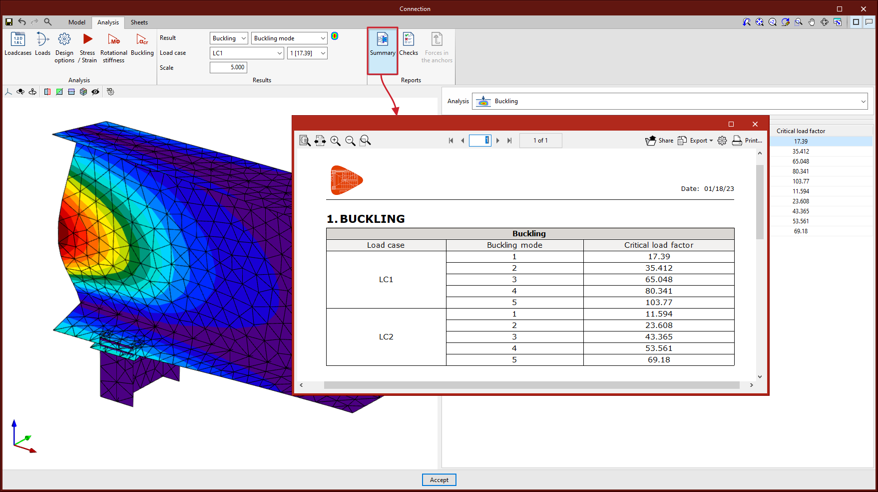
The joint summary report includes a table showing the number of buckling modes analysed for each load case, as well as the critical load factors associated with each of them.
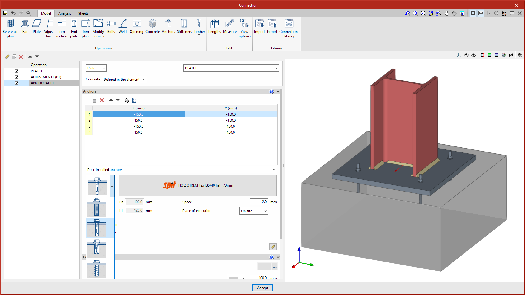
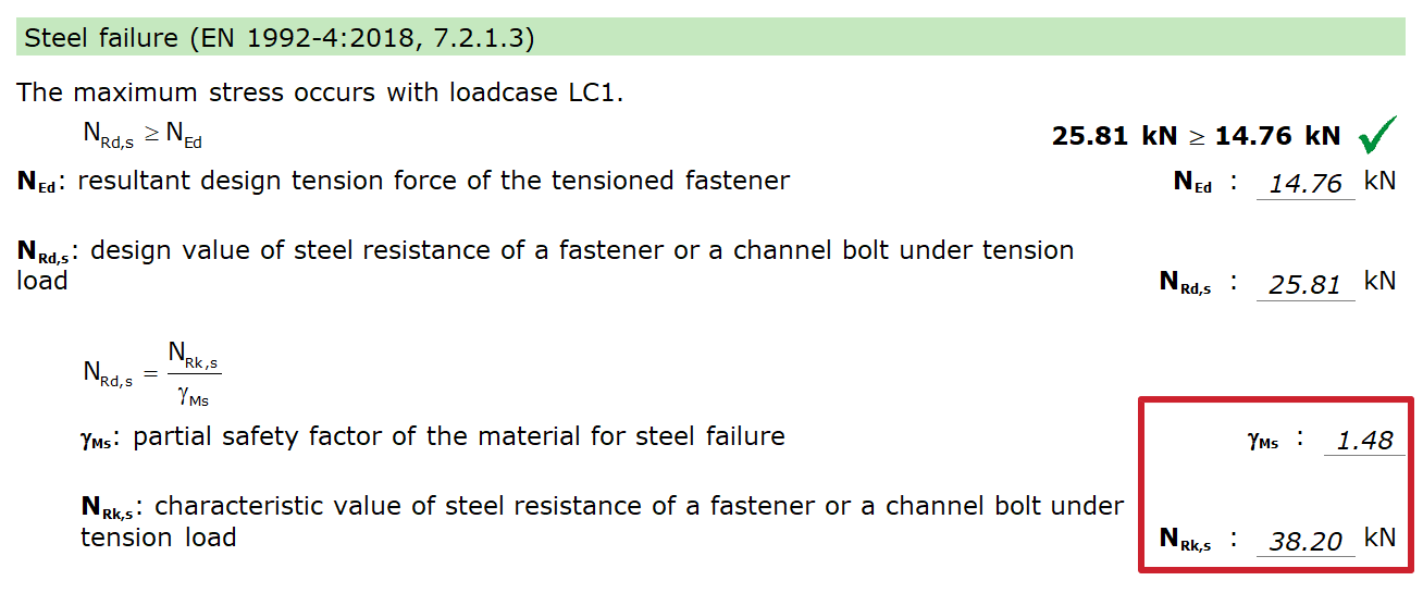
SPIT brand mechanical anchors for concrete fixings
In version 2023.e of CYPE Connect and StruBIM Steel, post-installed mechanical anchors from the SPIT brand catalogue can now be used as concrete fixings in baseplates. The checking of these elements is carried out in accordance with the criteria in the EN 1992-4:2018 standard, based on the data provided in the corresponding ETA (European Technical Assessment) for each fixing.
The previous version (2023.d) implemented chemical anchors from the same brand.
The SPIT brand post-installed mechanical anchors introduced in the 2023.e version are the following:
- Torque-controlled expansion fixings
- Drop-in fixings
- Concrete screws
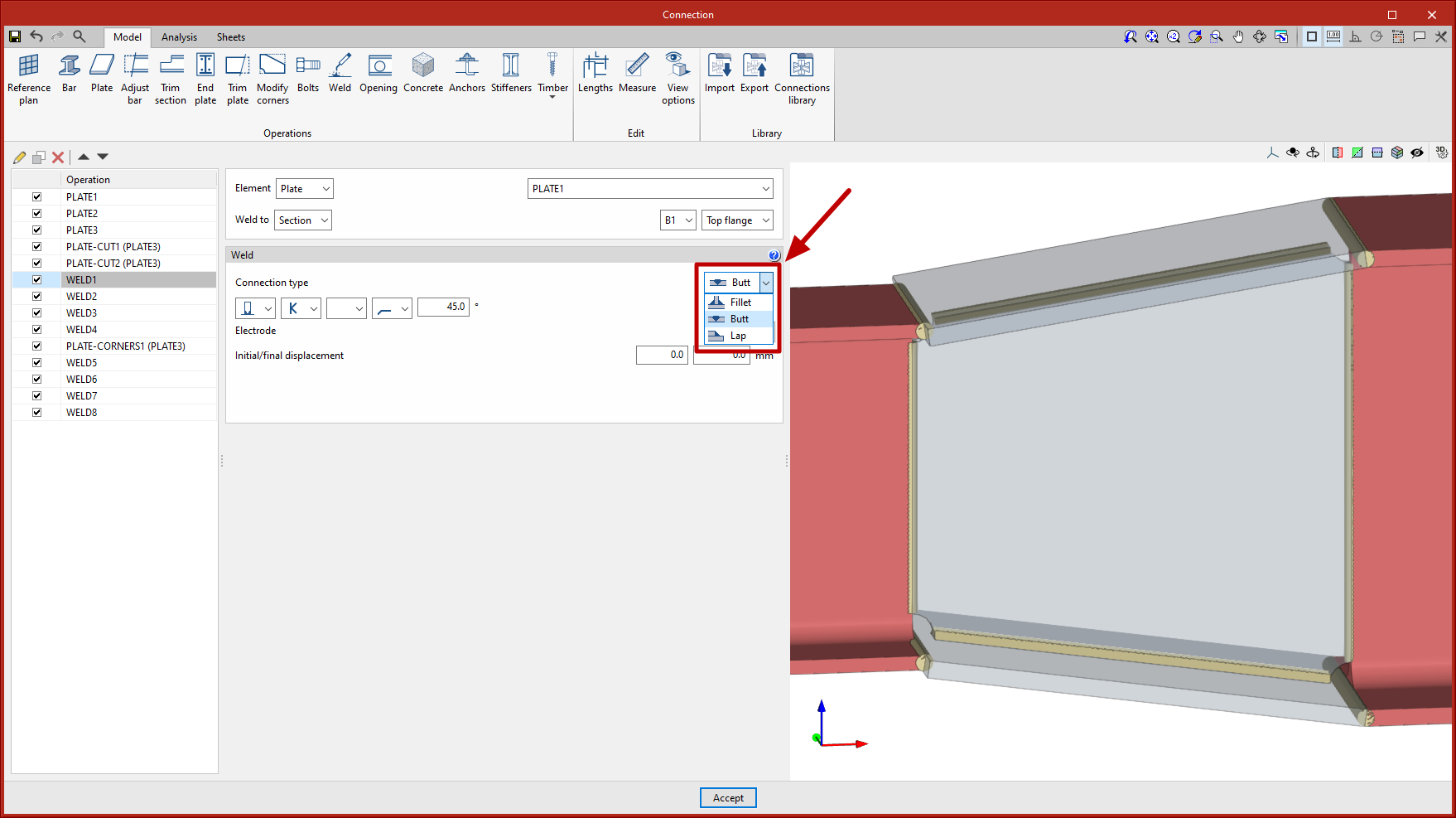
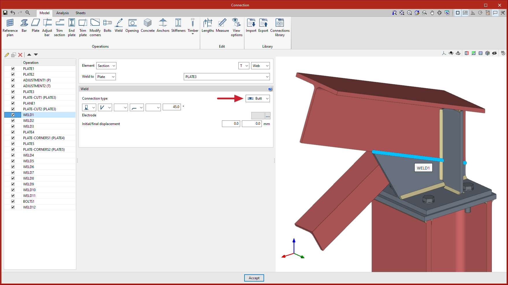
Butt welds
Up until version 2023.e, sections and plates could be welded in either "Fillet" or "Lap" joint types. As of version 2023.e, welding the edges of plates as “butt” welds is also possible, i.e. the parallel edges of plates and sections can be joined end-to-end whether they are parallel or not.
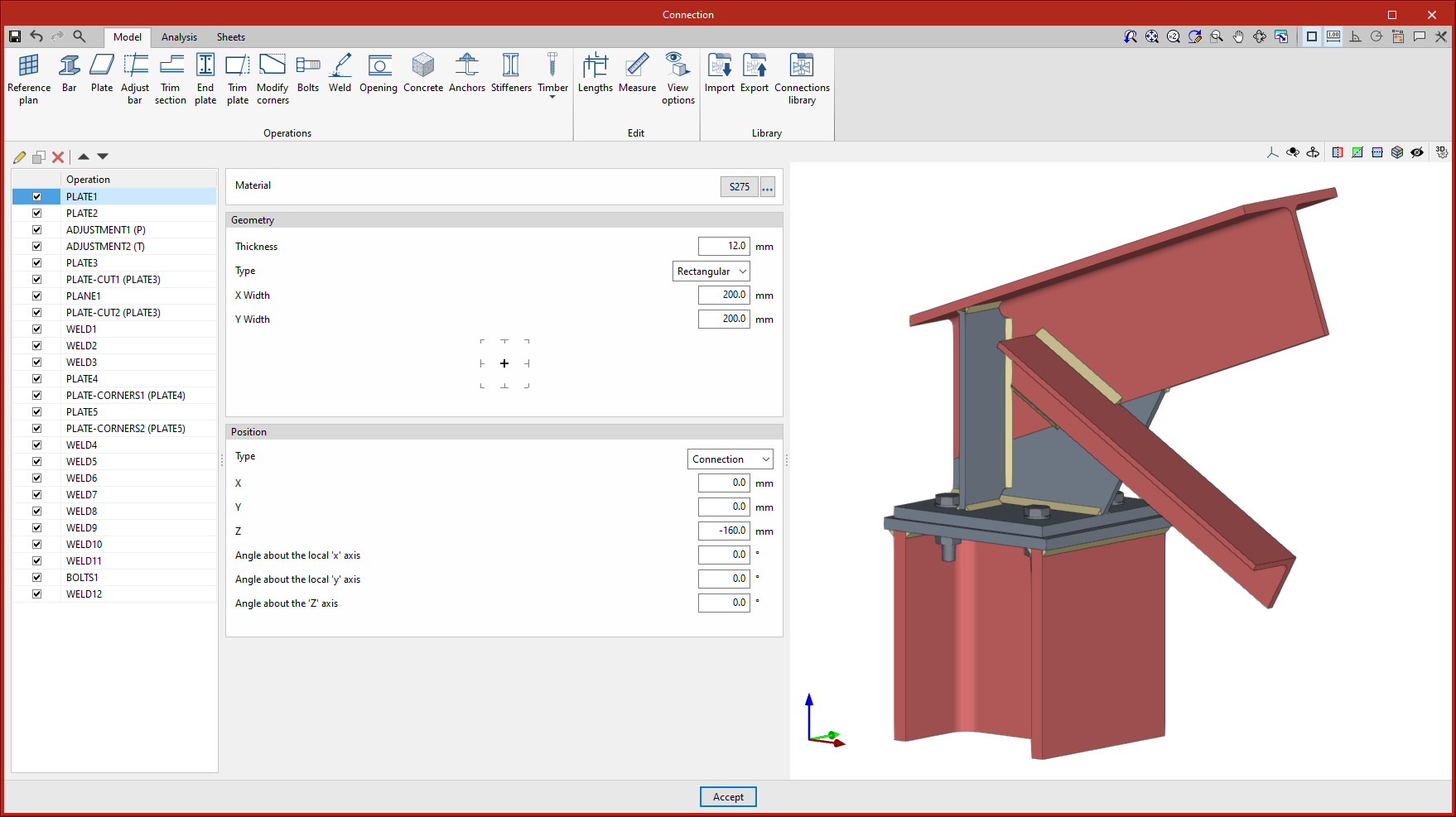
New types of sections: T-section and plate
Up until version 2023.e, the program could work with rectangular section timber bars (CYPE Connect) and double T, C, angle and rectangular hollow section steel sections (CYPE Connect and StruBIM Steel). In version 2023.e, two new types of sections have been implemented for both CYPE Connect and StruBIM Steel:
- Steel T sections
- Plates
These sections will be available both as the node's own bars and as additional bars in the "Bar" operation.

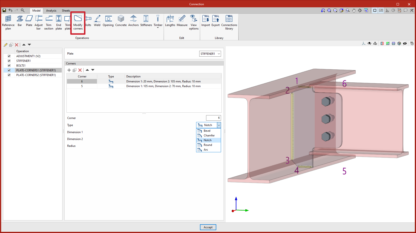
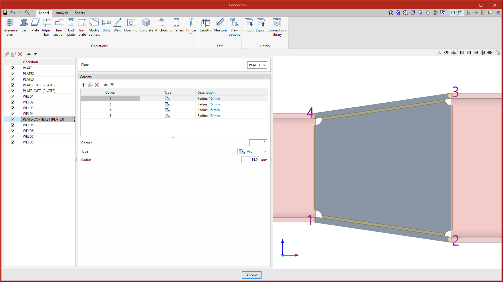
New operation "Modify corners"
There is a new operation available: "Edit corners". This operation allows users to edit the corners of plates. Bevel, chamfer, notch, round and arc cuts can be defined.
When the operation is added and the plate is selected, the corner indices are marked on the screen. A cut can be added to each corner of the selected plate.
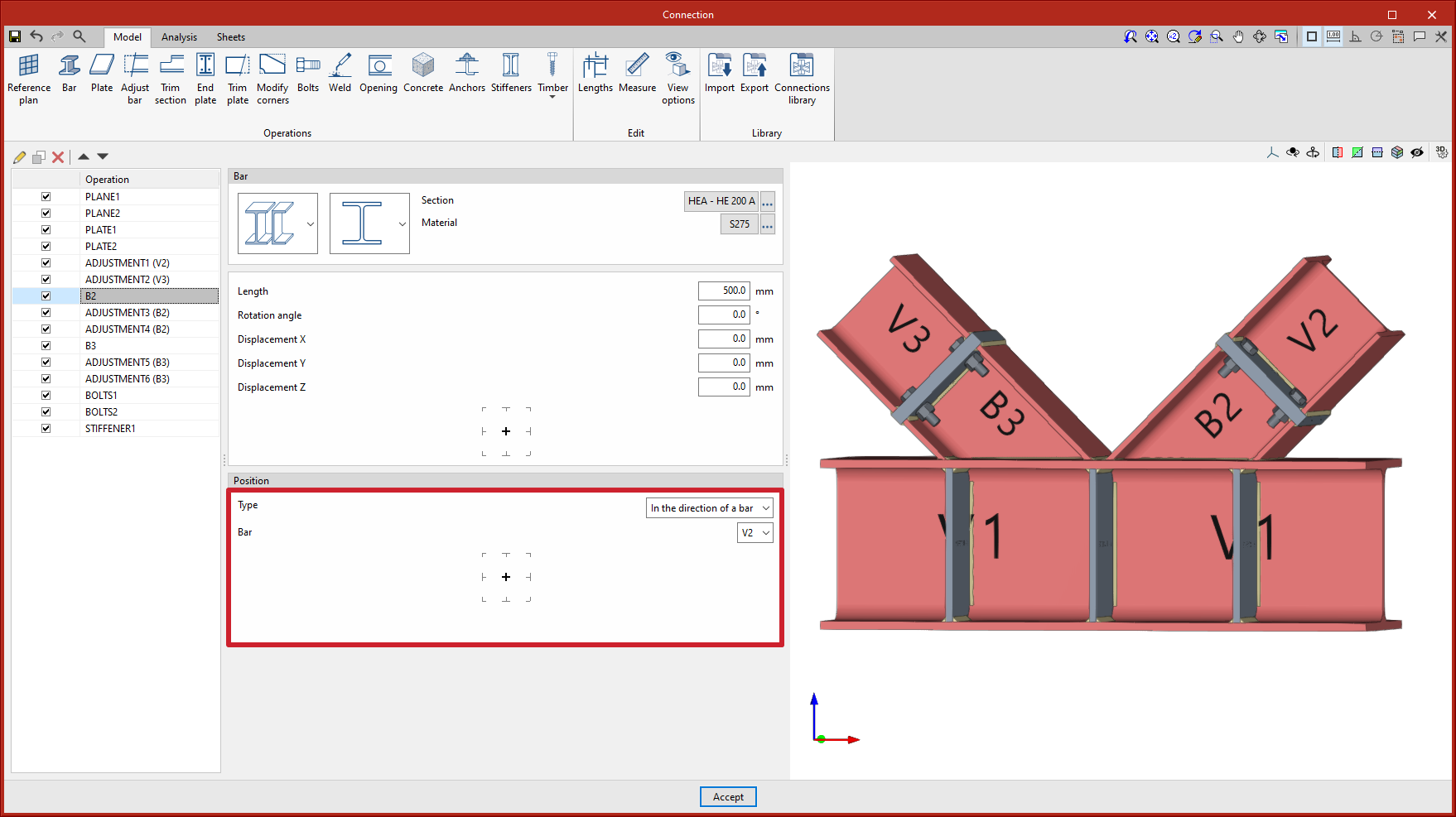
Improvements to ease the entry of additional bars at joints
The "Bar" operation includes a new option to position additional bars in the direction of another bar. This improvement makes it easier to align bars.
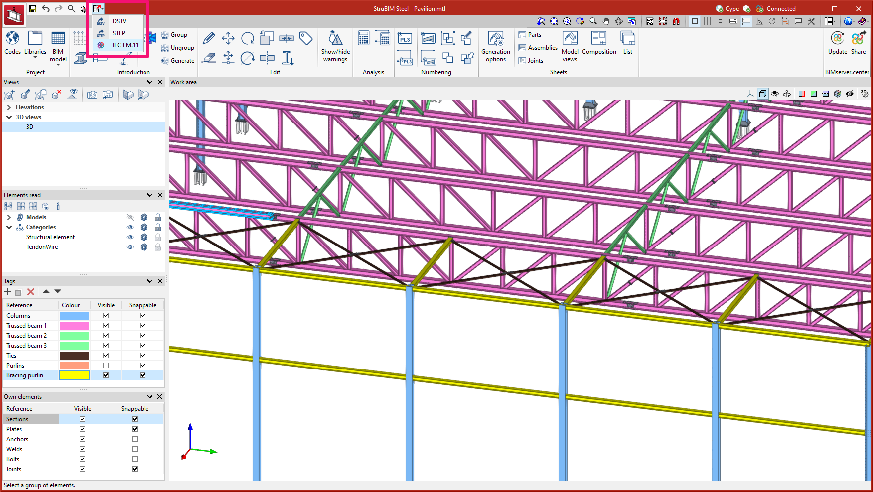
Exporting in IFC EM.11 format (new module)
In version 2023.e, the export to IFC EM.11 format has been implemented.
"EM.11 is a specification (MVD - Model View Definition) of the IFC format that contains information for the automated fabrication of structural steel. StruBIM Steel can export sections, plates, welds, bolts and anchors using this format.
Exporting to IFC EM. 11 format works as a StruBIM Steel module. In order to be used, the "Export detailing of the steel structure (IFC EM.11)" module must be included in the StruBIM Steel user license.
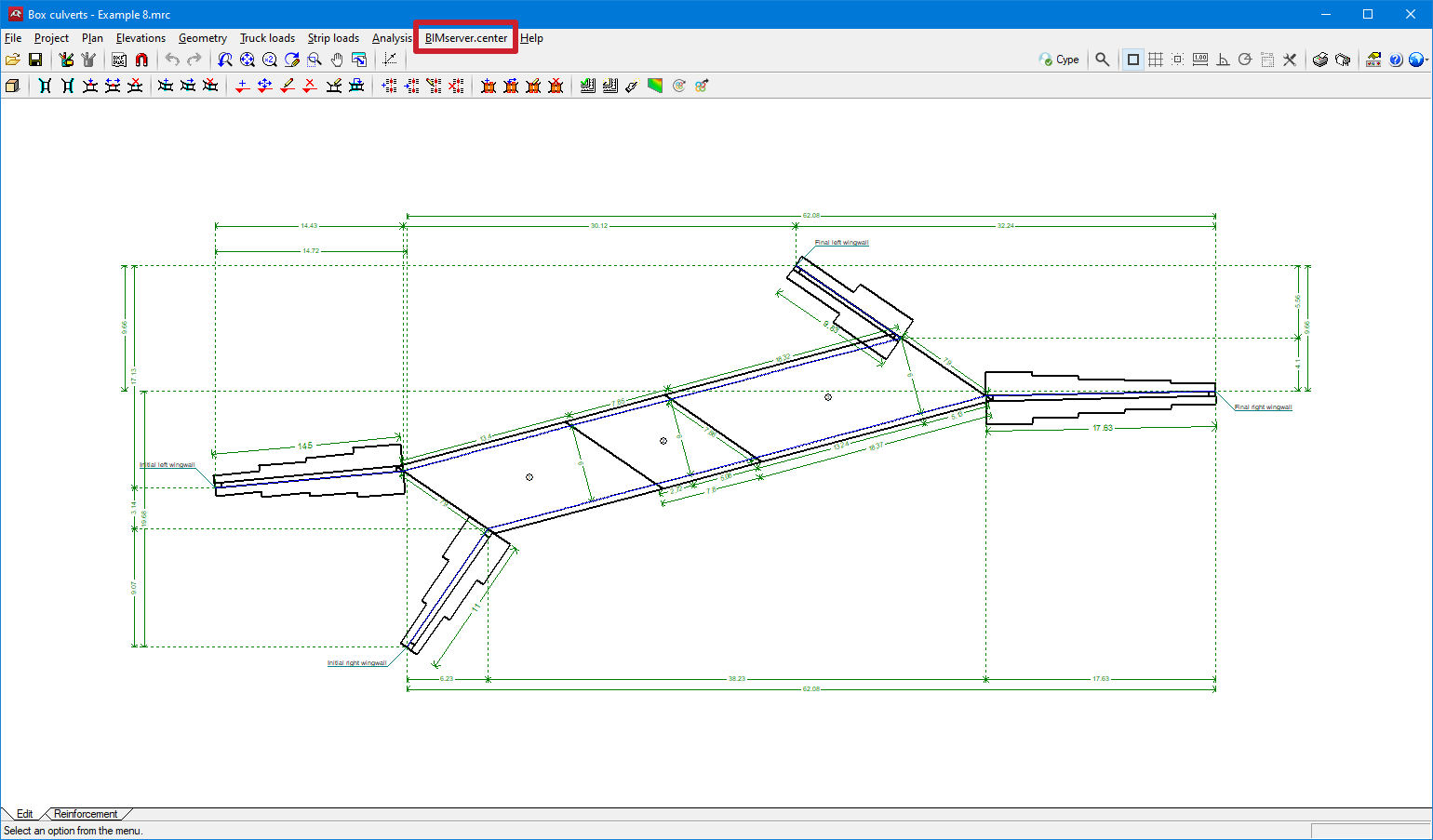
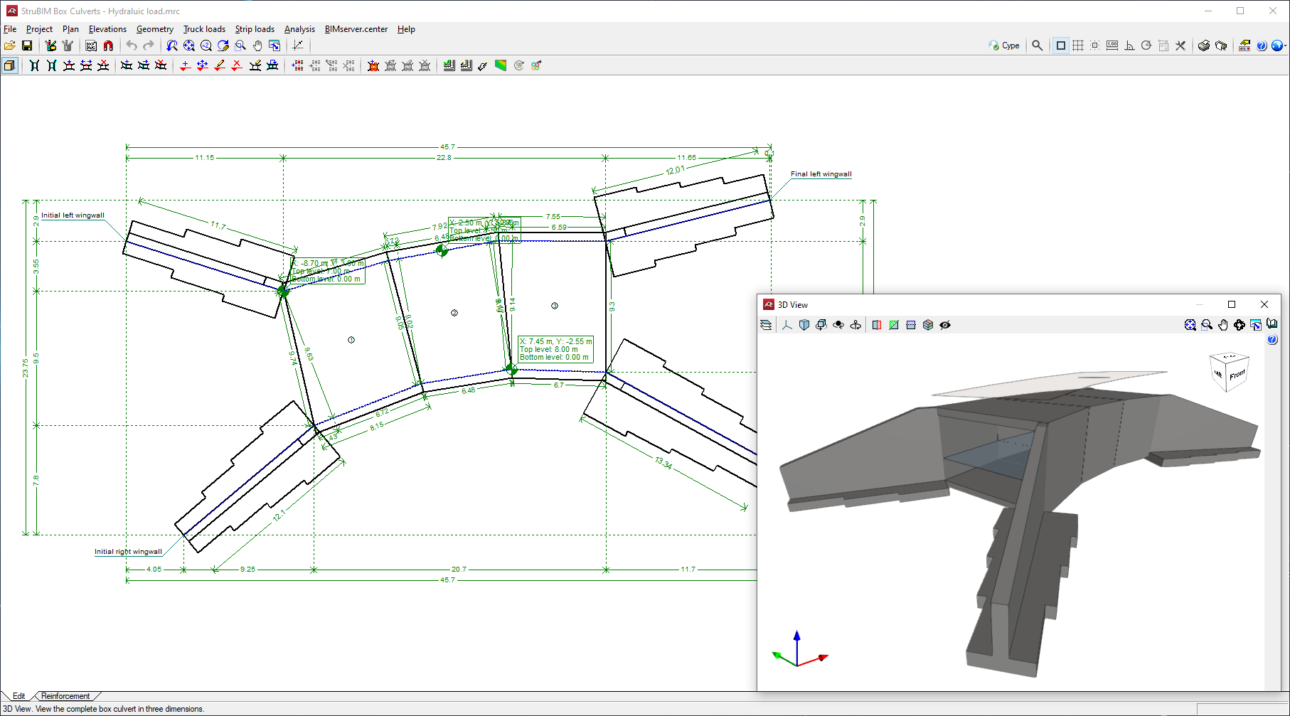
Connection with BIMserver.center
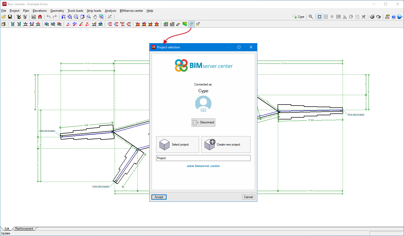
In version 2023.e, the Box culverts program has been connected to the BIMserver.center platform.
The top toolbar includes the "BIMserver.center" menu that contains the "Update" and "Share" options.
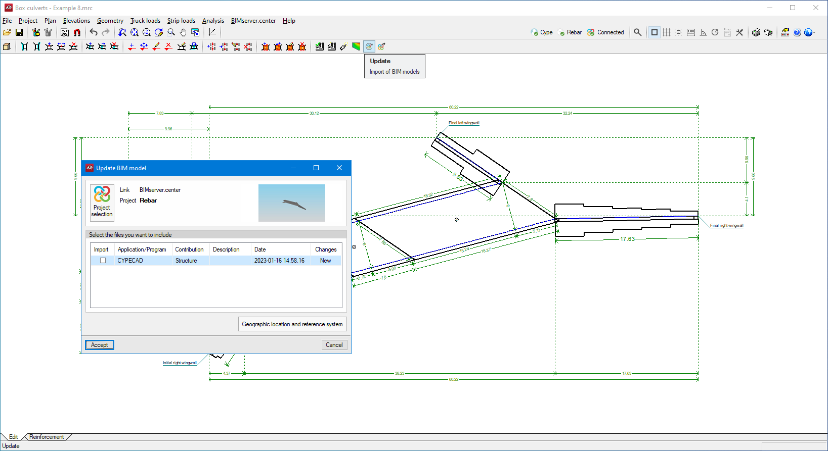
When the job is not connected to a project, it can be connected to a BIMserver.center project (new or existing) via “Update”. If the job is already connected to a project, users can access the management panel of the files to be included as links via "Update".
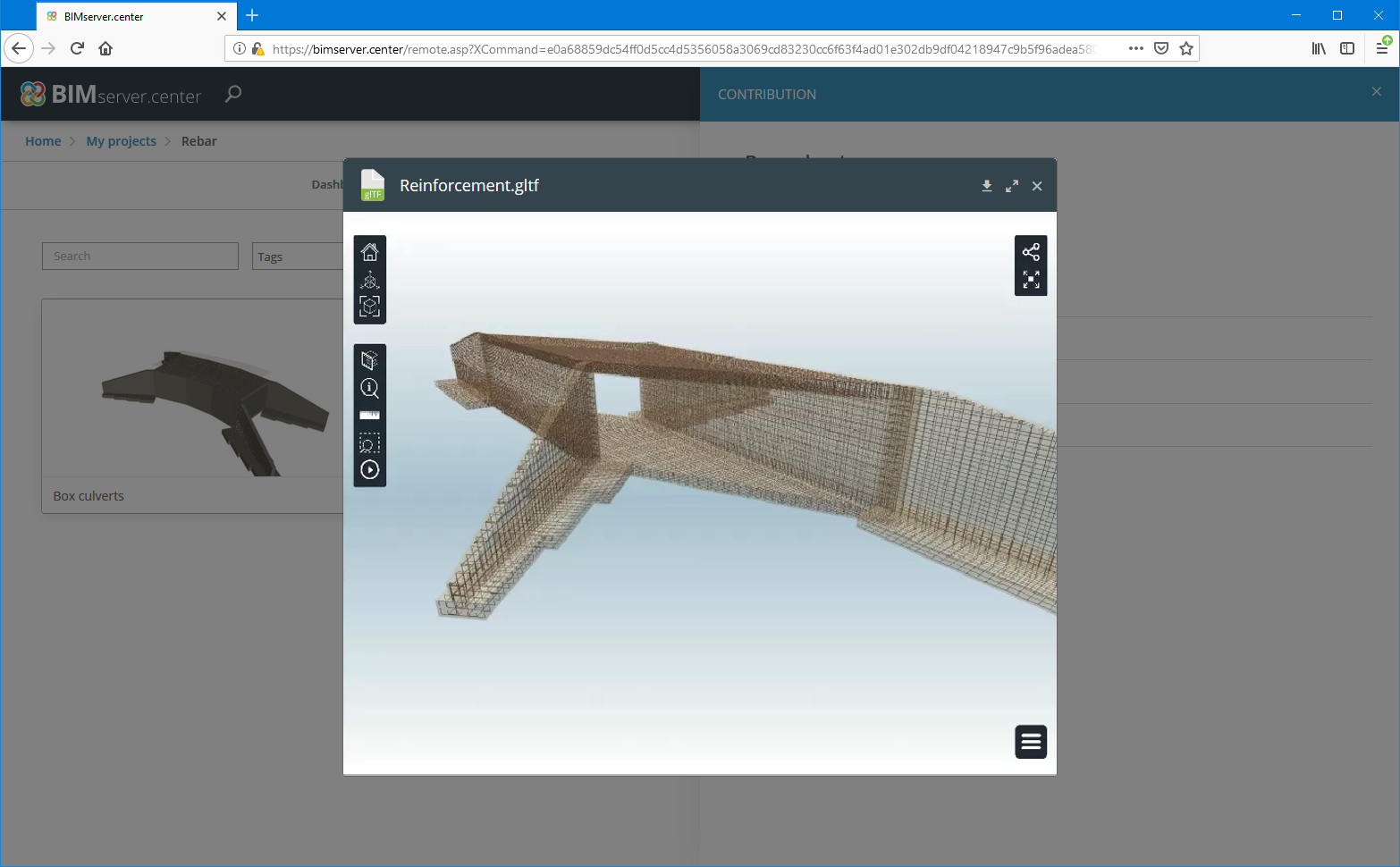
When using the “Share” option, the program exports the following to BIMserver.center:
- Geometry of the structure
- Reinforcement in GLTF format
- Reports in PDF format
- Drawings
- Reinforcement for StruBIM Rebar
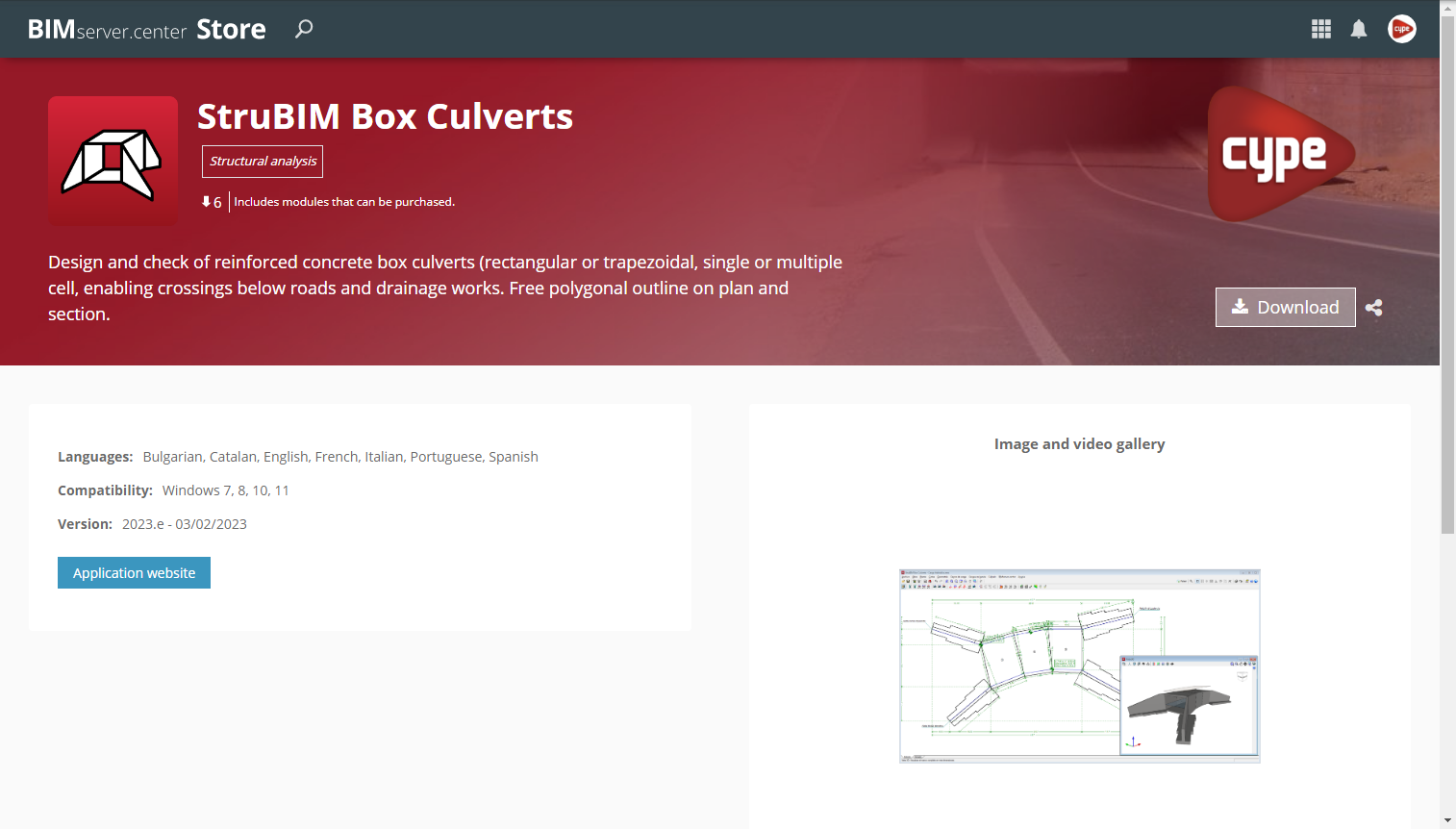
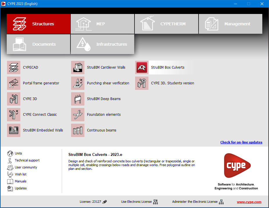
Application name change and download at BIMserver.center
Version 2023.e was released on 19 January 2023. As of 3 February 2023, the "Box culverts" program has been renamed "StruBIM Box Culverts" in all of its installation languages and is also available for download from the BIMserver.center platform.
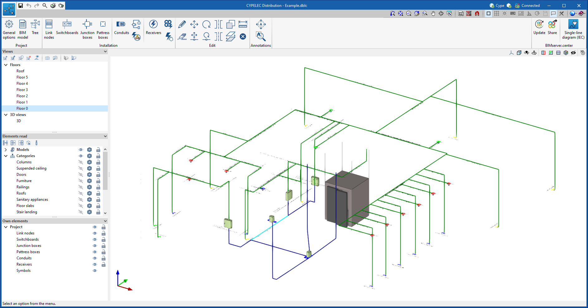
Representation of the feeder and the indoor installation in different colours
In order to identify the lines belonging to the feeder installation and the lines belonging to the indoor installation, they are shown in different colours: blue for the feeder installation and green for the indoor installation.
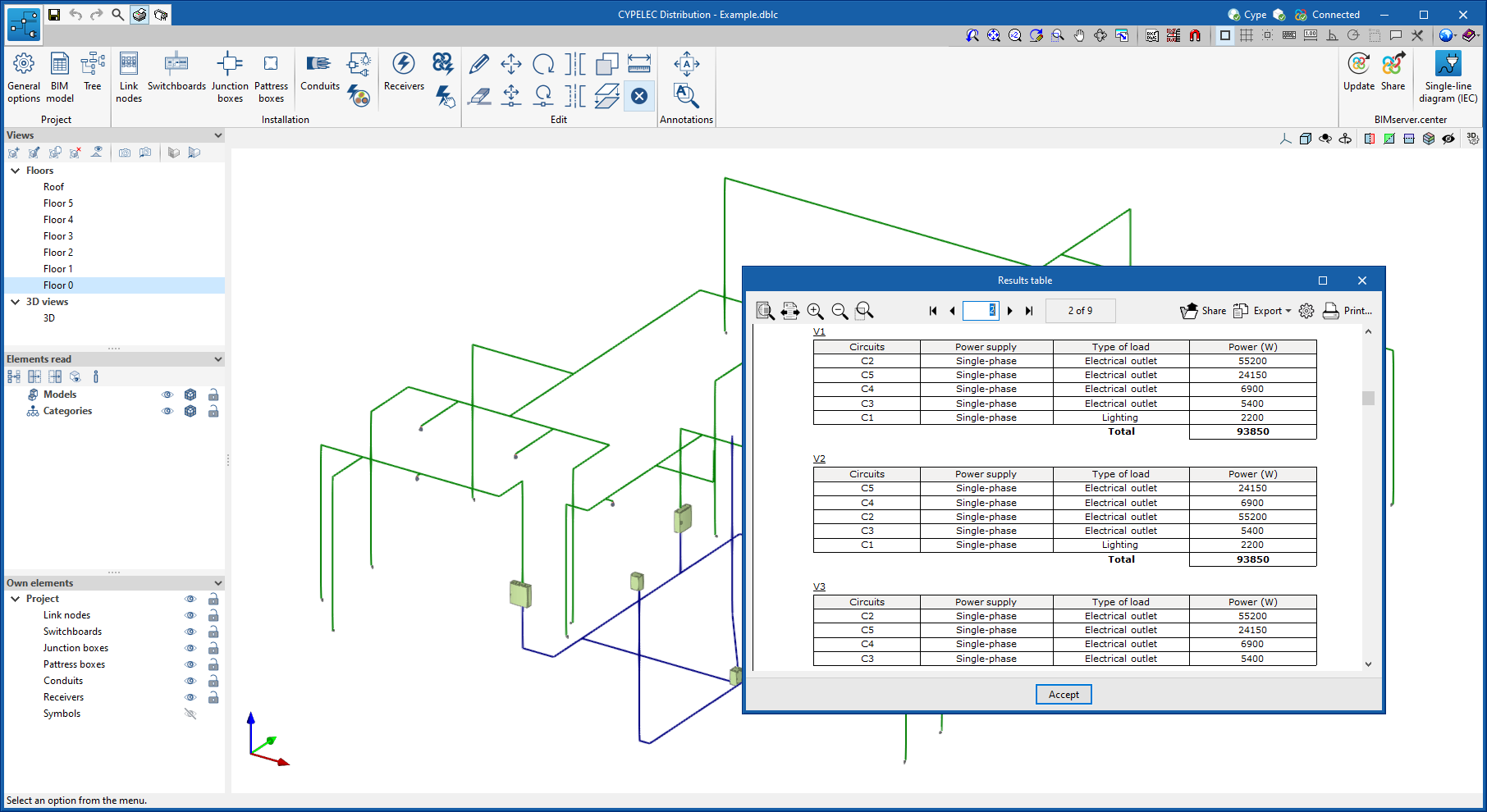
Switchboard and circuit reports
A report of the switchboards and circuits contained in the project can now be obtained. For switchboards, each one specifies the circuits it contains together with their total installed power. For circuits, the loads they feed are specified together with their nominal power.
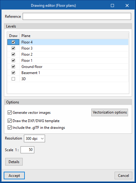
Drawing management
Creating the best possible project requires the configuration and editing of drawings.
In version 2023.e, drawing management in CYPEFIRE has been improved. Plans can now be generated in vector format and 3D information from the ".glTF" files included in the project can be added to them, as shown in the image.
This offers greater flexibility and viewing for the different parts of the job, as drawings can be generated in the new formats or users can continue working as before.
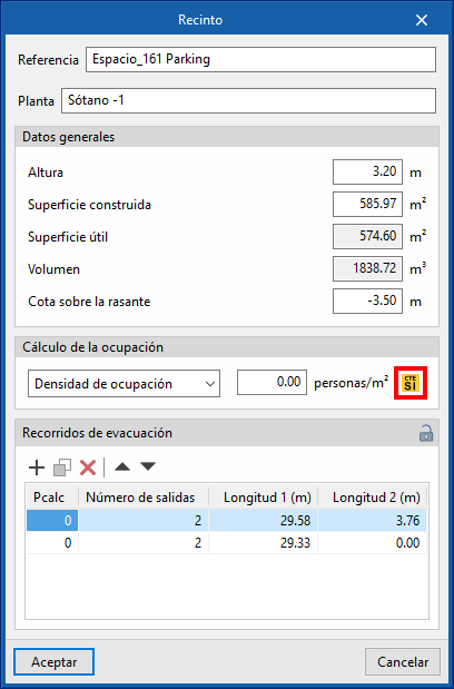
Occupancy density table
Each time a new project is started or the link with a BIM model is updated, CYPEFIRE offers users the possibility of associating the spaces imported from the architectural model with the occupancy density table of the associated codes for each country, making it much easier to calculate the number of occupants.
As of version 2023.e, this option will also be available from the "Space" dialogue box, allowing users to access the desired code information without creating or updating the project again.
The occupancy density table can only be associated with spaces imported from the architectural model when the program has been installed in a language with associated codes. In the current version (2023.e), the implemented codes are the Spanish standards "CTE DB SI" and "RSCIEI". Therefore, in this version 2023.e, this association is only possible when the program has been installed in Catalan and Spanish.
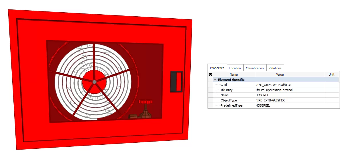
Export to IFC and equipment update
Version 2023.e includes an update of the main fire safety equipment (fire extinguishers, fire hose reels, alarm buttons, dry standpipe, etc.). The 3D representations and symbol orientations have been updated to facilitate their placement on the project.
Furthermore, this equipment and the designed evacuation routes are included in the export carried out by CYPEFIRE to the IFC format.
Updated user's manual for the program
The program's user manual has been updated in English, French and Spanish.


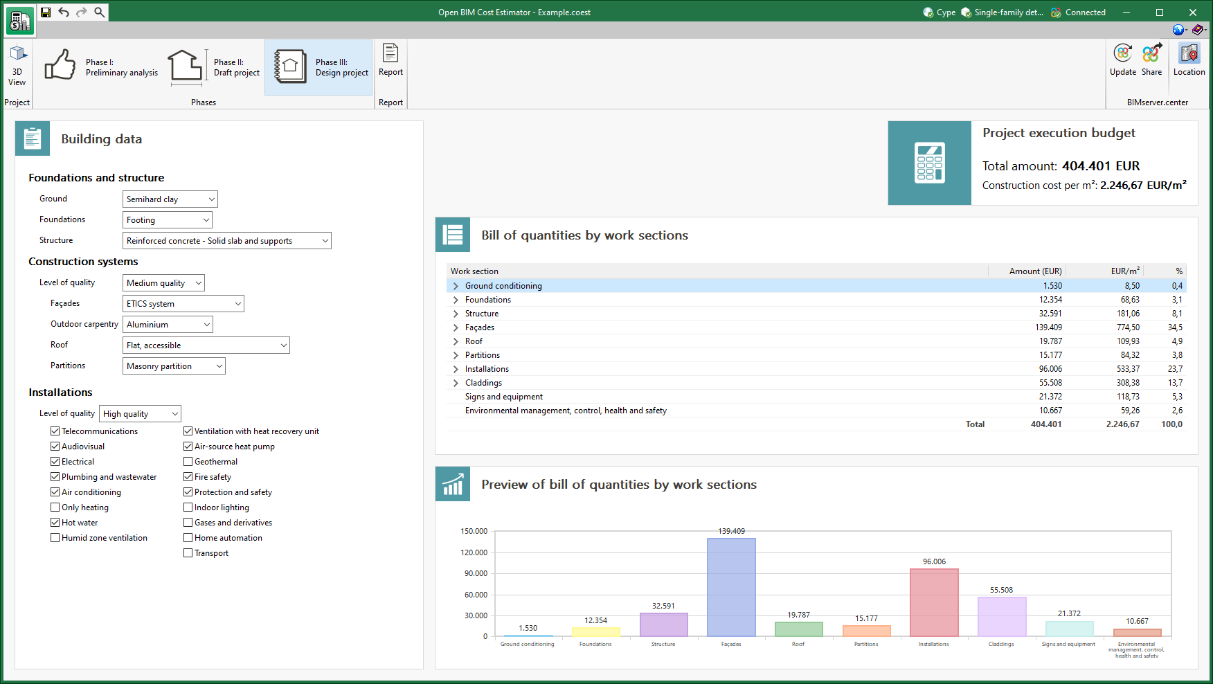
Updated cost database
The cost database used by the application to determine the project execution budget of the job has been revised. Projects carried out with previous versions of the program will be automatically updated when they are opened with version 2023.e.
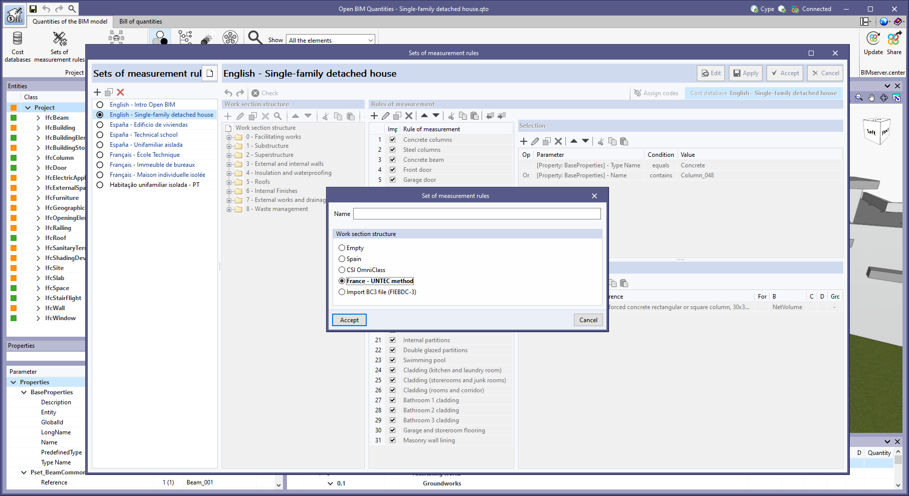
“UNTEC method” work section structure
The predefined work section structure "France - UNTEC Method" has been added when creating a new "Set of measurement rules" (Open BIM Quantities) or a "Mapping file" (applications with a "Bill of quantities" tab).
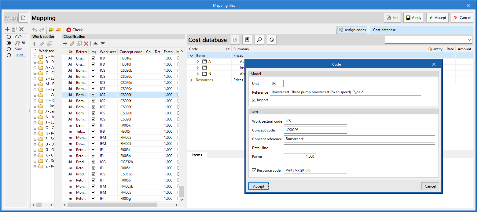
Mapping to resources
As of version 2023.e, applications with a "Bill of quantities" tab can map their model's elements to an item's resource. For this purpose, in the editing of a mapping file, the "Resource code" option has been added when components are modified in the "Classification" list. By activating this option, users can specify the resource code on which the quantity of the model element will be mapped. This will be added to the breakdown of the concept described by means of the "Concept code" and "Concept reference" fields.
When the resource indicated in the mapping file is a cost breakdown in the associated cost database, only the unit components of this breakdown shall be assigned to the concept.