Update history​

CYPELEC Core

New method for connecting applications to the BIMserver.center platform

The mode of communication between Open BIM applications and the BIMserver.center collaborative work platform has changed. In previous versions, the applications used the "BIMserver.center Sync" tool to upload and download the files of the contributions associated with the project from the platform. This tool was downloaded from the BIMserver.center platform or installed together with the installation of the platform applications if users so desired.

From version 2024.a onwards, applications are now able to work directly with BIMserver.center without an intermediary. That is, without the need for the "BIMserver.center Sync" tool.

This modification will improve the performance and efficiency of Open BIM applications significantly. By removing this dependency, the applications have more autonomy and the waiting times for communication between BIMserver.center Sync and the program have been considerably reduced. The process of downloading contributions has also been optimised, as users no longer need to obtain the entire content of a project from BIMserver.center in order to work, but only the contributions to be read.

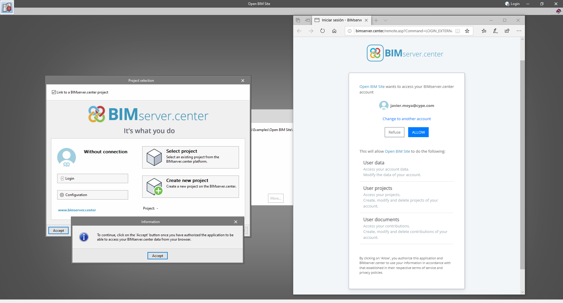
The way of authenticating a BIMserver.center user in the applications has also been modified. Now, this process is carried out within the BIMserver.center web platform. To do this, the application with which the user is working will run the user's default browser when the "Login" button is pressed. When the credentials are entered, or after opening the browser if the user is already connected to the platform, an authorisation page will be displayed. This page details the resources the application is requesting access to and two buttons for granting or denying this access.

The authorisation must be carried out for each application. Once access has been granted, it is saved for the next time the program is run and there is no need to perform this process again for that application.

As well as performance improvements, changes have been made to the user interface of the Open BIM applications regarding the connection to BIMserver.center.

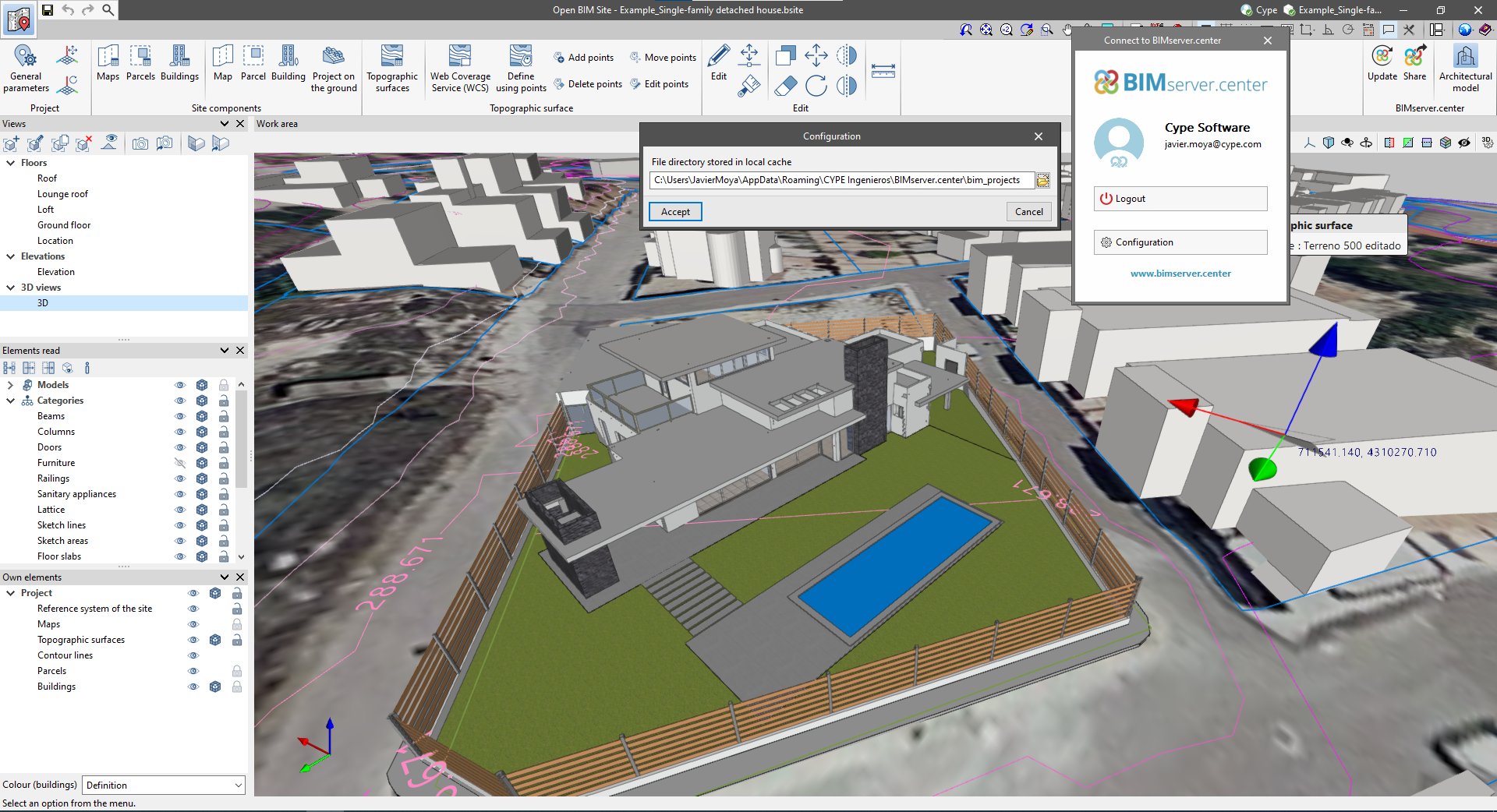
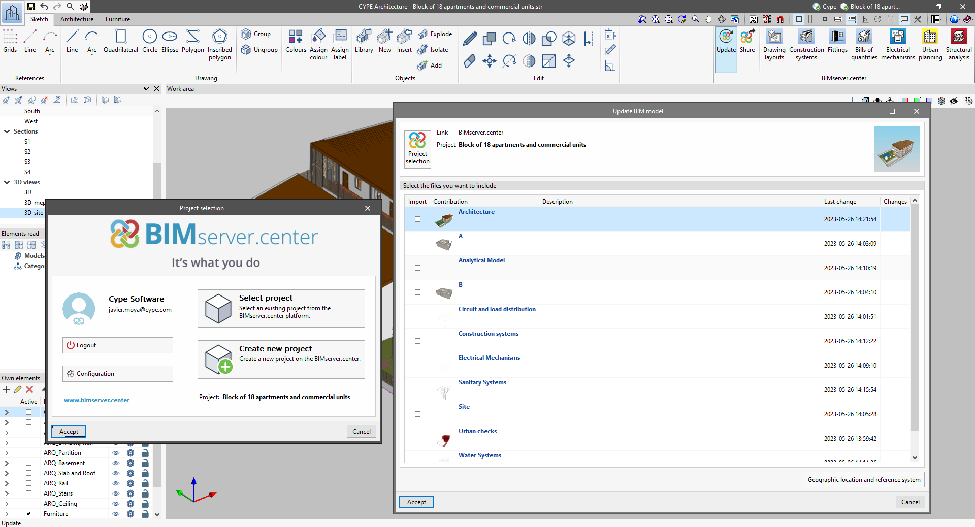
  • The "Connect to BIMserver.center" window now includes a "Configuration" button. Clicking it launches a menu from which you can edit the "File directory stored in local cache". This is the path where the files that make up the contributions will be downloaded when working with them from the applications. In previous versions, this location could be selected from the BIMserver.center Sync tool.
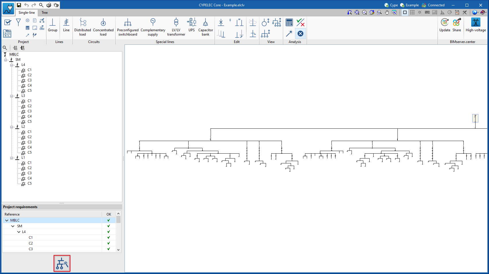
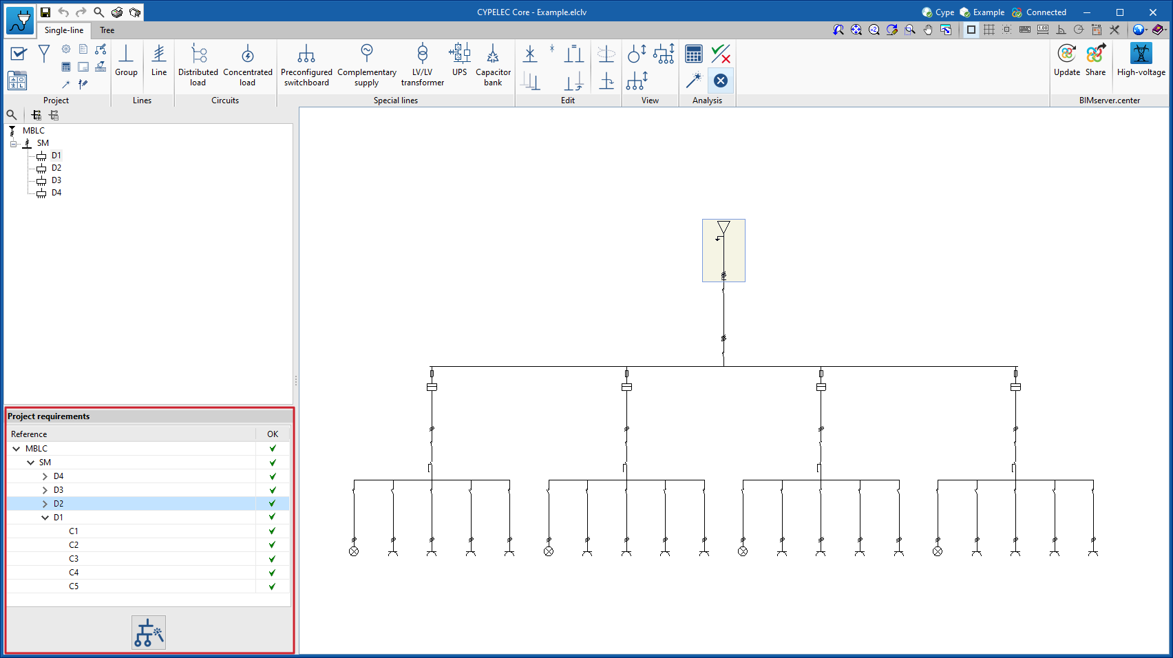
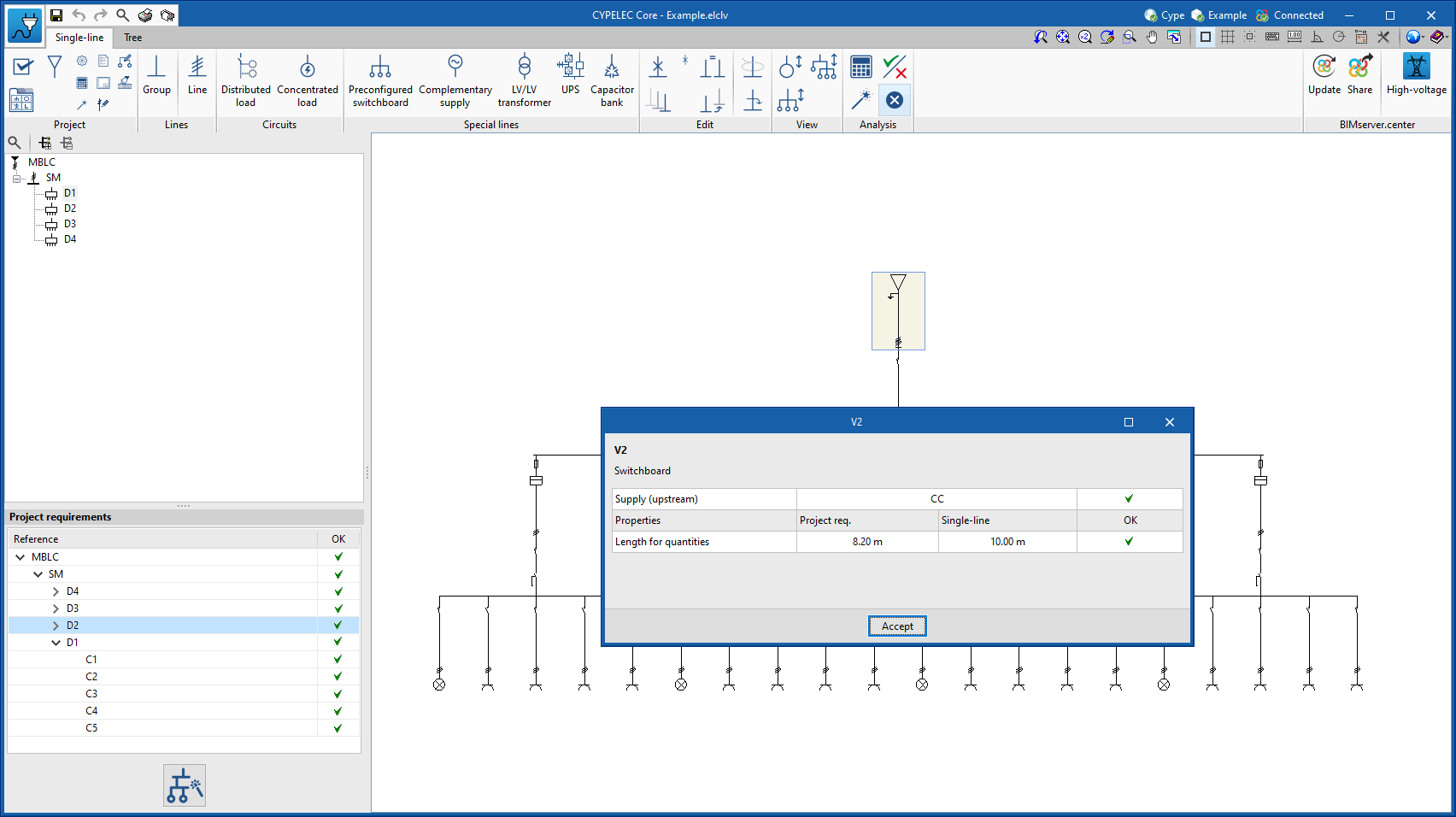
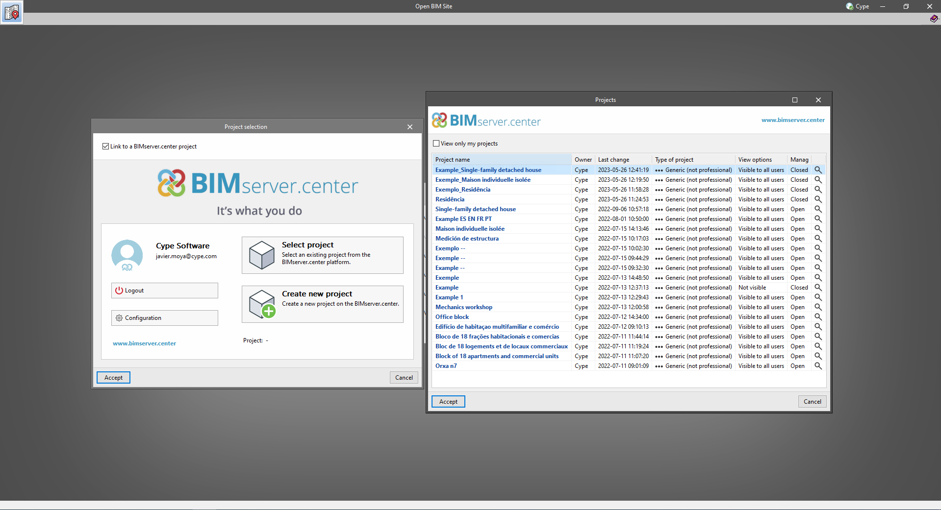
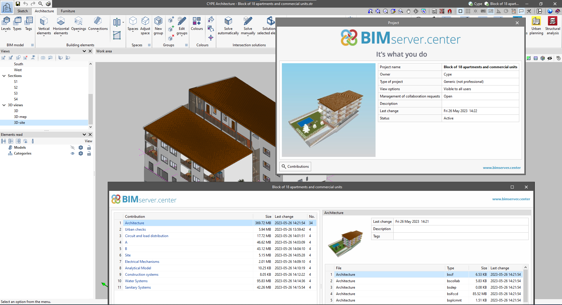
  • The appearance of the "Project selection" window has been modified.
  • In the "Select project" list, the "View only my projects" option has been added to show only the projects where the connected BIMserver.center user is the owner. Icons have also been included for the "Type of project" column in order to make it easier to identify them. The detailed data of a project now shows the image of each contribution, the description and the tags.
  • The "Review new contributions" and "Review updated contributions" options have been added to the "Create new project" window.
  • The list for selecting contributions ("Import BIM models") now includes the images of the contributions and the tags. The name of the contribution will be displayed in blue to indicate that the owner is the logged-in user.
  • When sharing a contribution or selecting contributions during the process of linking to a BIMserver.center project, a progress window will appear during the upload or download process.

To work in BIMserver.center with versions of Open BIM applications prior to 2024.a, users must continue to use the BIMserver.center Sync tool. This is still available for download from the platform and was included in the installation packages of the CYPE Open BIM applications prior to 2024.a.

New line: Anticipated panel for power demand

A line called "Anticipated panel" has been added to represent a power supply line to a switchboard or sub-switchboard without having to indicate its internal circuits.

This line acts as a final line and is indicated in cases where users wish to provide a switchboard or sub-switchboard with its expected power demand but without developing its internal circuits.

Improved information displayed in the single-line diagram

The information on the results displayed at the bottom of the single-line diagram has been improved. This information can be displayed under the electric load or shown in the form of a properties table.

The information shown is configurable and will depend on the selection indicated in the single-line diagram options.

Material quantities by switchboard report

The program can now display the report of material quantities not only globally for the project, but also by switchboards and sub-switchboards. To do this, simply activate the option available in "Results presentation".

This option also affects the structure of the BC3 export report which will also be structured by switchboard and sub-switchboard if the option is enabled.

Replacing a line with a preconfigured switchboard

It is now possible to replace any line in the single-line diagram with a preconfigured switchboard in the program, such as the switchboard of a standard dwelling.

This tool is particularly useful when importing from the CYPELEC Distribution program, in which solely the feeder has been incorporated, and the single-line diagram is to be completed with repeated switchboards.

Graphical editing of the reference system of the model

Since version 2022.a, the applications integrated within the Open BIM workflow via the BIMserver.center platform include a tool for managing project reference systems. This option is available from the configuration window that appears when linking or updating a BIMserver.center project via the "Geographic location and reference system" option. As of version 2023.d, the applications now allow users to run a graphical environment where they can visually define a reference system for their model. To do this, the "Geographic location and reference system" window now contains the "Visual editing of the local reference system of the model" option.

From the "Visual editing of the local reference system of the model" window, the origin and orientation of the reference system of the model can be indicated in the workspace with the "Define the reference system of the partial model" tool. Both the axes of the reference system of the model, which we have just entered and the axes of the reference system of the site can be viewed in the workspace. The latter appears with a "Site" tag.

To make it easier to define the reference system, the 3D models corresponding to the BIMserver.center project contributions selected during the linking process are displayed. The management of the visibility and object snaps of these models is carried out from the "Elements read" menu in the left sidebar of the window. The "Views" menu can also be found in the same options bar, from which different types of 2D and 3D views of the model can be generated. These tools can already be found in several CYPE applications. For more information on how they work, please refer to the User’s Manual for the 3D work environment tools available in CYPE applications.

Apart from 3D models, 2D drawings or plans can also be imported from CAD files (".dxf", ".dwg", ".dwf") or images (".jpeg", ".jpg", ".bmp", ".png", ".wmf", ".emf", ".pcx"). These files and object snaps are managed through the "DXF-DWG Template" and "Template object snaps" options accordingly.

Once the editing is complete, the coordinates and orientation of the reference system of the model with respect to the reference system of the site are moved to the corresponding fields in the "Geographic location and reference system" window.

Font size

The "Font size" option has been added to the general configuration menu of the applications. This tool allows users to increase or decrease the basic size of the font used in the user interface of the programs. Thanks to this implementation, the accessibility of the applications has been improved while also ensuring the correct visibility of the content on devices with different screen resolutions.

To enter a "Basic size" the "Set custom font size" option must be checked. The size users can enter is the application's basic font size. Any other font sizes that may exist in the program's interface will be automatically modified proportionally according to the change in the basic size.

It is important to note that, as this is a common parameter, its modification will affect all installed CYPE tools.

Generating project specifications

If project requirements are generated from the information that may exist in the BIM project (see the new feature from this version 2023.b "Import and checking of the specifications from the CYPELEC Distribution program"), a receiver is added that automatically imports the diagram.

Import and checking of the specifications from the CYPELEC Distribution program

Should the BIM project contain electrical distribution information provided by the CYPELEC Distribution program, this information will be processed by CYPELEC CORE so that this program shows the electrical project specifications to be met in the left-hand margin of the work area.

Compliance with these project requirements is based on the verification of the following points:

  • The connection hierarchy of the wiring diagram must be followed so that all lines and circuits are defined and connected according to the imported diagram.

  • The requirements must be met for each of the lines and circuits. As a result, there are three possible scenarios:
    • The measuring length must be met for lines belonging to feeders and supply lines to switchboards or sub-switchboards.
    • If a circuit belongs to a switchboard and a circuit with a concentrated load is chosen, the total active power demand of the circuit and the measuring length must be met.
    • If a circuit belongs to a switchboard and a circuit with distributed load is chosen, the definition and distribution of each of the loads along the supply circuit must be met, in addition to the active power demand and measurement length, and the electrical properties of each of the loads must be met for each of them.

It is worth mentioning that in order to meet the requirement of the measurement length of a circuit, the sum of the design length plus the sum of the additional length must be equal to or greater than the required length. Both lengths are present in the edit panel of a circuit as shown in the following image.

Class B and class B-SI (Super Immunised) residual-current devices

Class selection for residual-current devices has been expanded. The new added classes are class B and class B-SI (Super Immunised).

Additional cable length in circuits

When editing any type of circuit that can be defined in a single-line diagram, the possibility of entering additional cable length is included. This length may include, for example, the connection between junction boxes and switches to complete the lighting points or branches that the circuit may include in its installation that may not have been considered for the cable design, but which have been taken into account for its total bill of quantities.

The total quantities of the cable are displayed in the material schedule report.


General improvements

Version 2021.g of CYPE’s programs is a closing version of the 2021 version.

As well as the new features and improvements expressly indicated in each version of CYPE software, process optimisation involving internal updates for all our programs is normally included. In each revision, all programs are systematically checked and changes are made to improve their performance, therefore, we recommend that our users (in this case those of v.2021) always update their version to the latest one, regardless of the country for which they are using CYPE software or the language in which it is installed.