Update history​​

CYPELEC Electrical Mechanisms

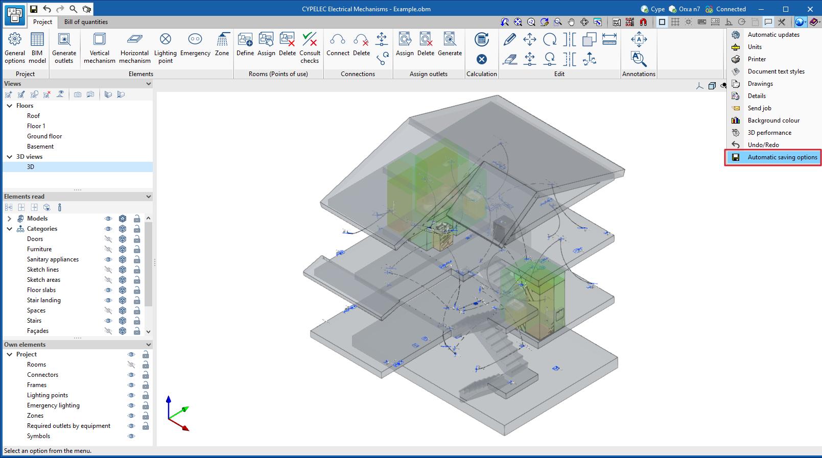
As of version 2023.d, all applications with a "Bill of quantities" tab now have a new set of tools that allow users to measure the work area. More specifically, the following options have been added:

  • Measure length
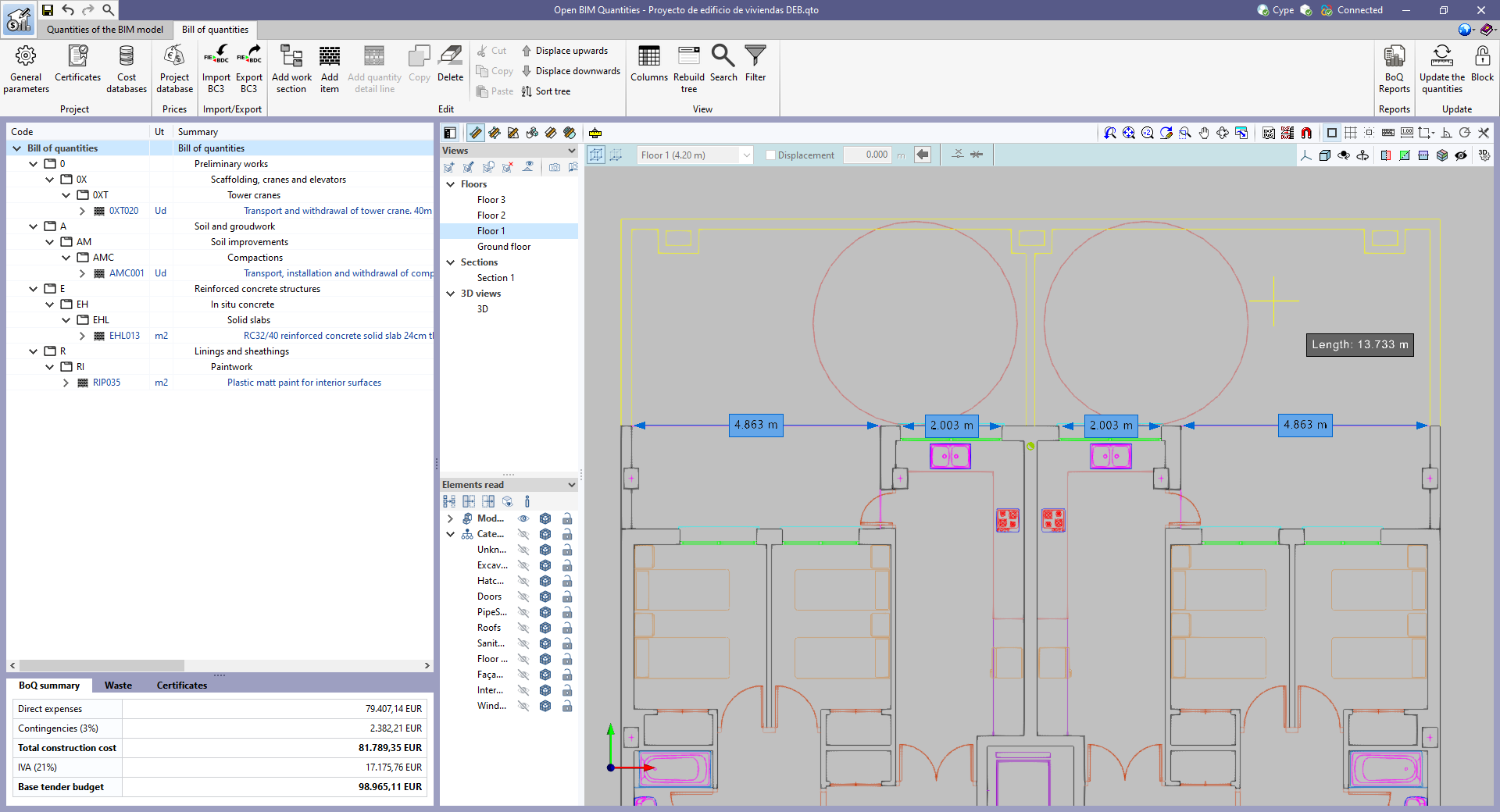
    The distance between points inserted in the work area can be measured. Several segments can be entered and the application will calculate the sum of the lengths of each one.
  • Measure area
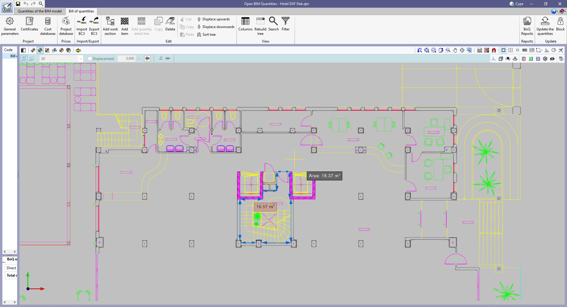
    The area of a polygon defined by points inserted in the work area can be measured. Several polygons can be entered and the application will calculate the sum of the areas of each one.
  • Measure angle
    The three-point angle inserted in the work area can be measured. Several angles can be defined and the application will calculate the sum of them.
  • Count the number of objects
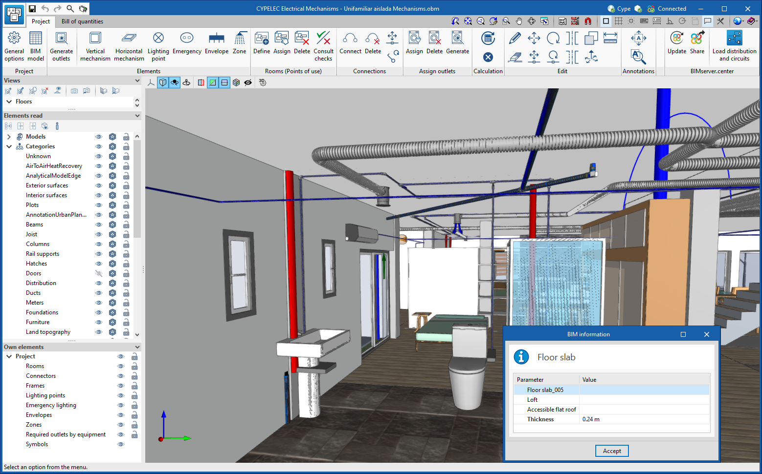
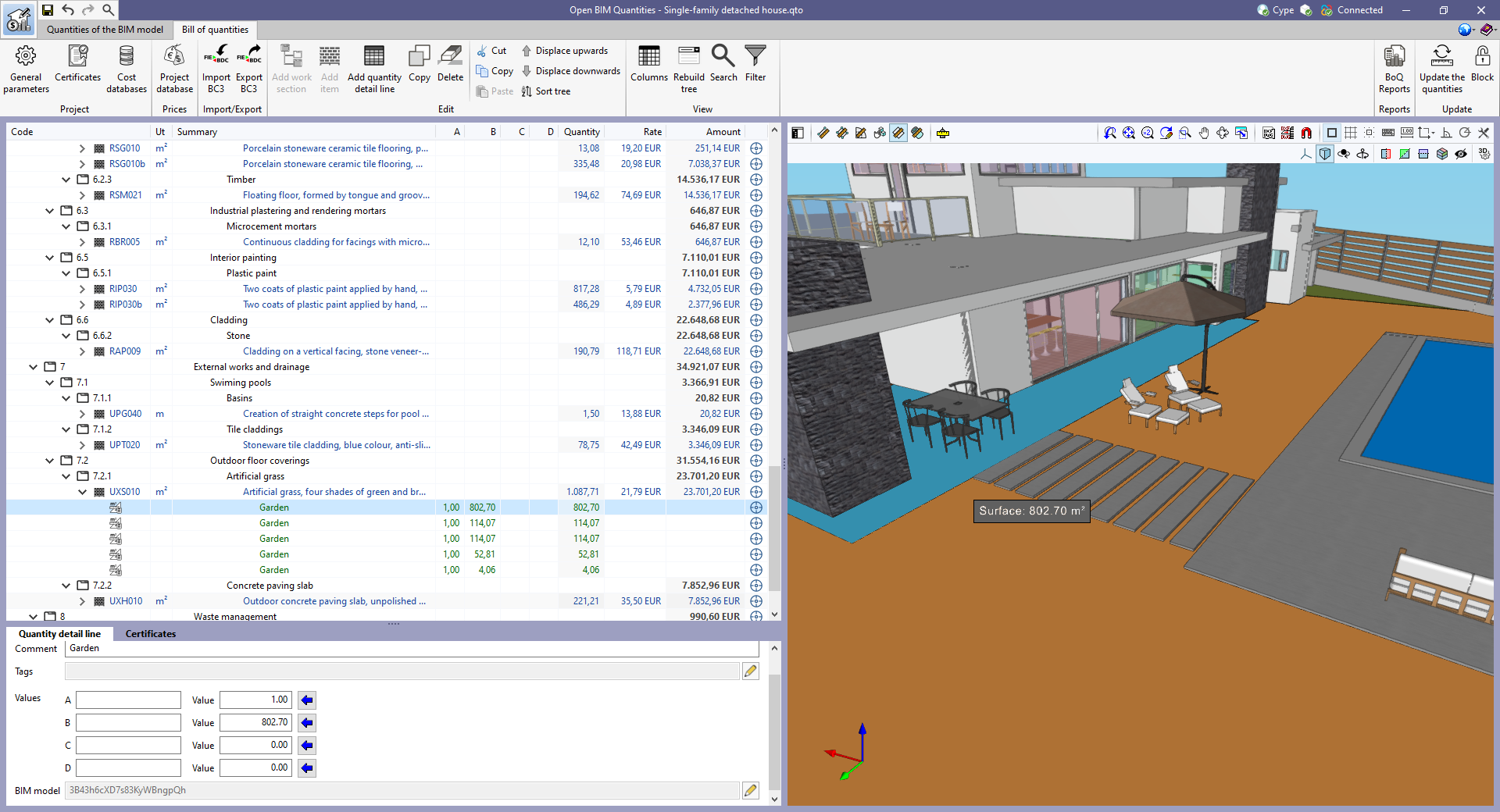
    The number of selected 3D model objects can be counted.
  • Measure the area of objects
    The total area of the selected 3D model objects can be measured.
  • Measure the volume of objects
    The total volume of the selected 3D model objects can be measured.

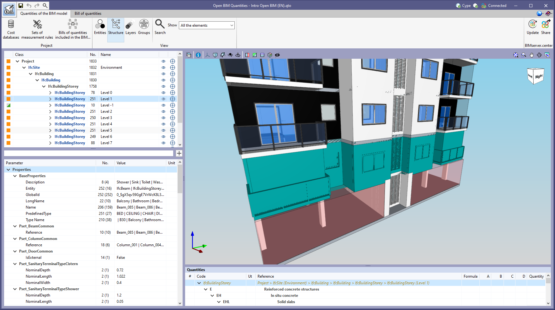
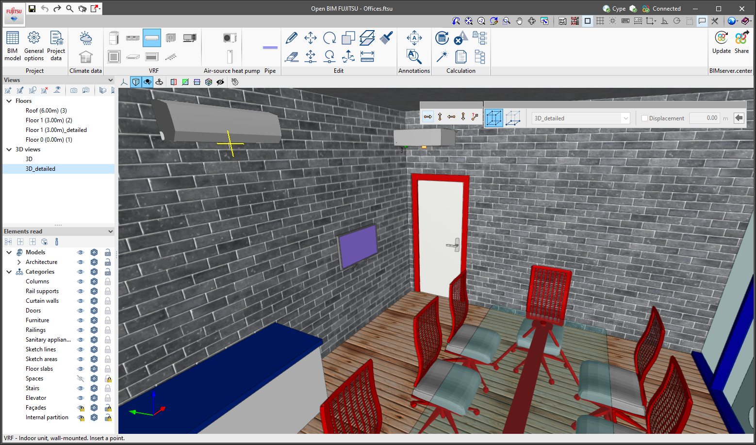
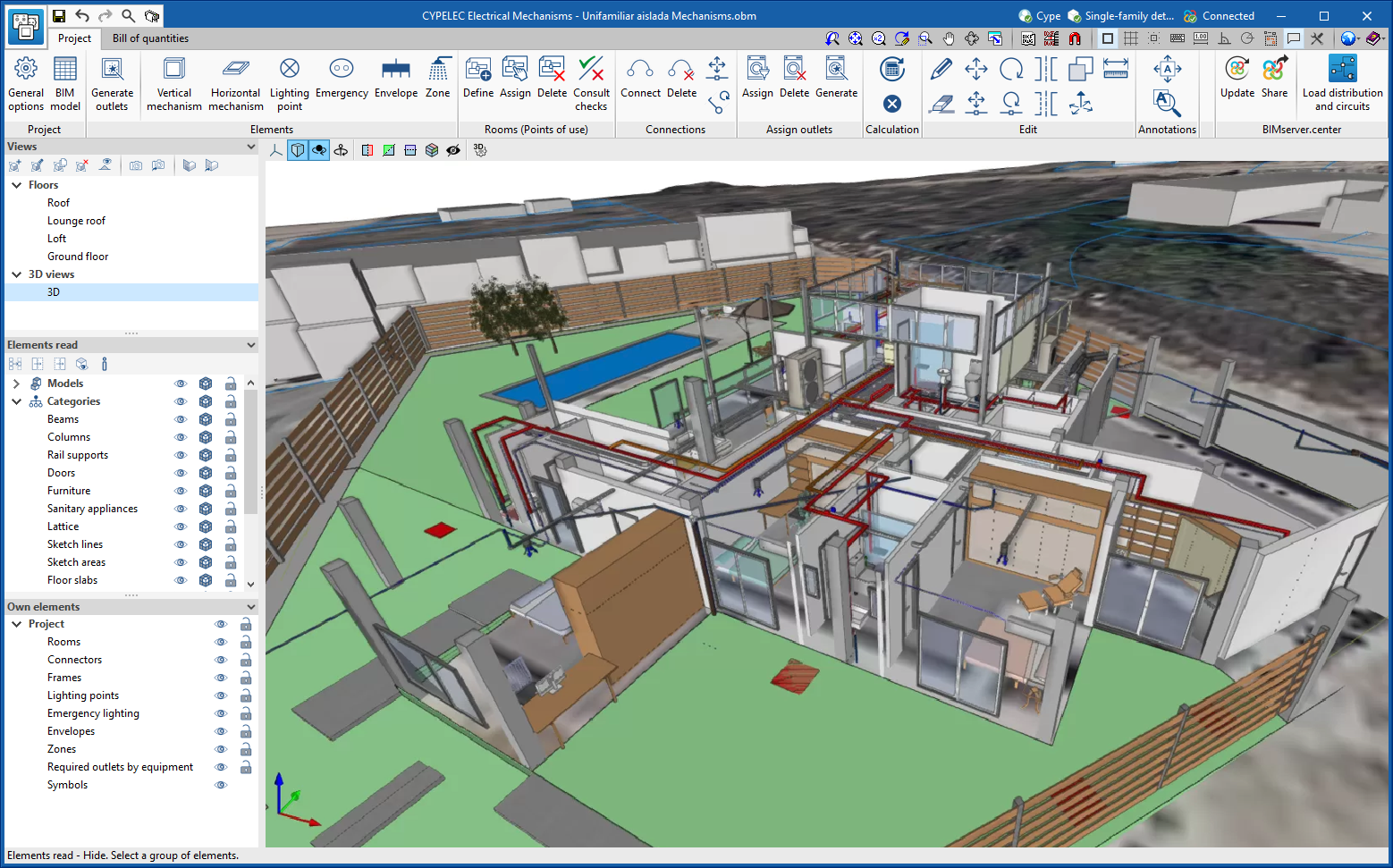
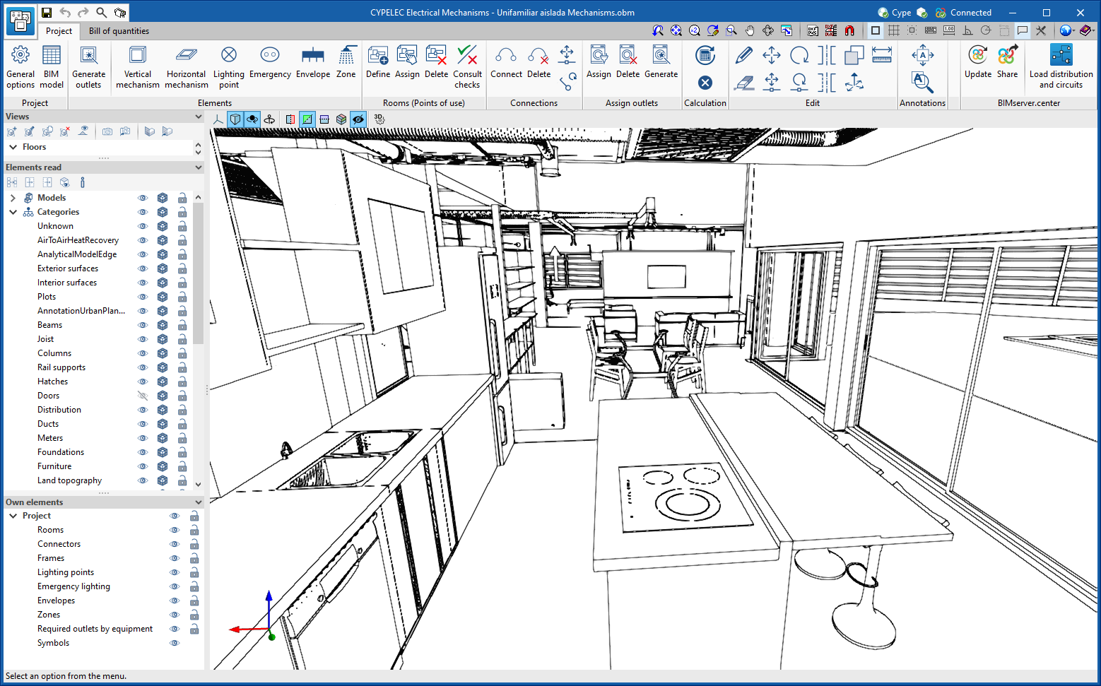
In order to make it easier to measure the quantities of the model, the work area has been modified to incorporate the 3D work environment tools that are already available in other CYPE Open BIM applications:
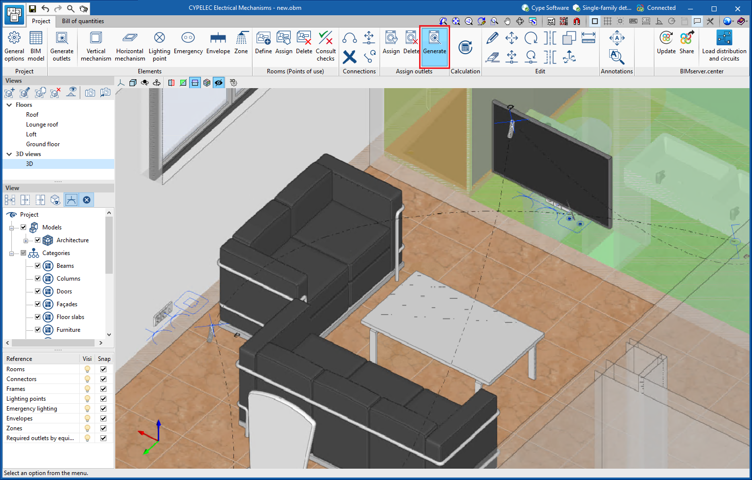
  • Defining views
    Different types of 2D and 3D views of the model can be generated from the "Views" panel in the sidebar of the work area.
  • Elements read
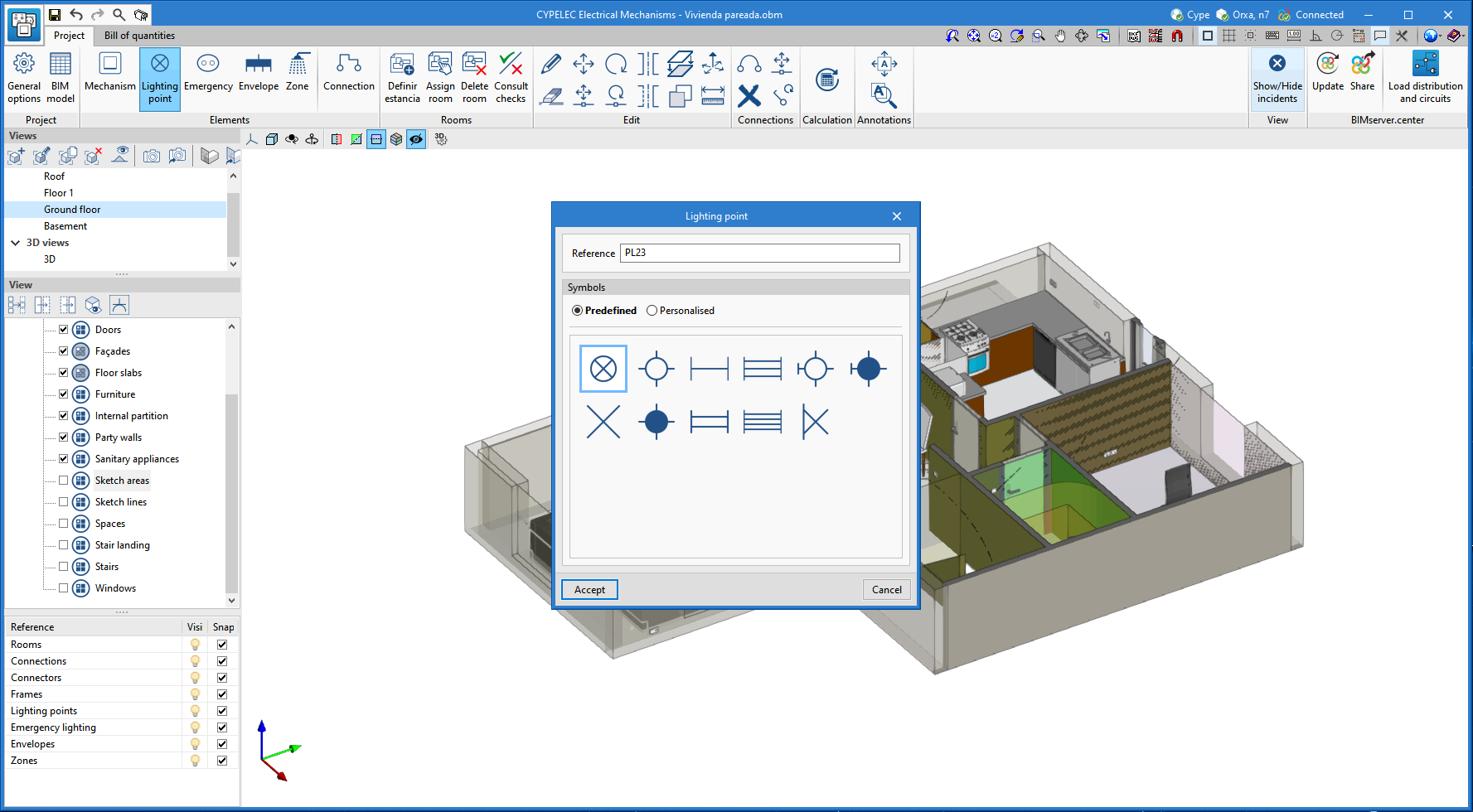
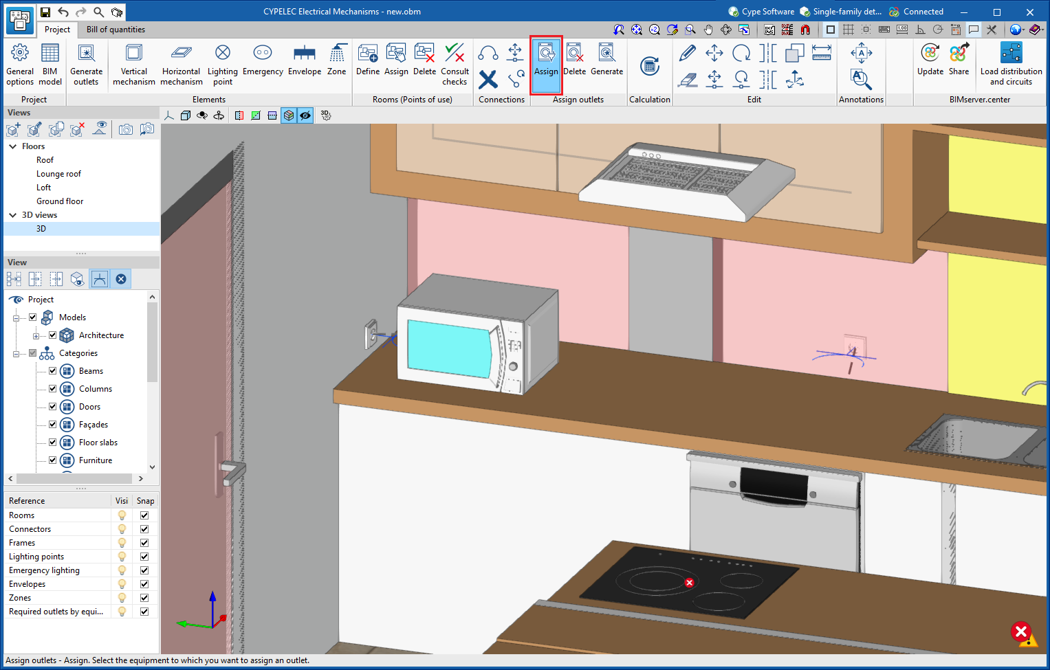
    The visibility and object snaps of model components can be controlled from the "Elements read" panel in the sidebar of the work area.
  • Inserting components
    When entering a measurement in the work area, the application provides a toolbar to make it easier for users to interact with the environment.

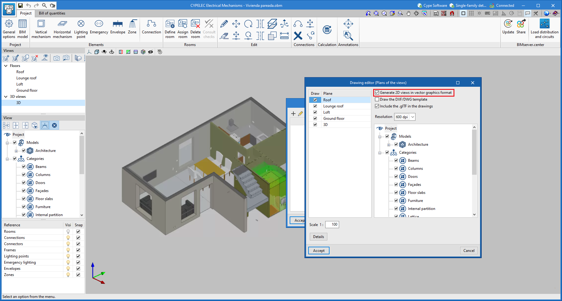
As well as measuring the 3D model, this new set of tools can be used to take measurements on plans or 2D drawings imported from CAD files (".dxf", ".dwg", ".dwf") or images (".jpeg", ".jpg", ".bmp", ".png", ".wmf", ".emf", ".pcx"). These files and the object snaps are managed through the "DXF-DWG Templates" and "Template object snaps" options respectively.

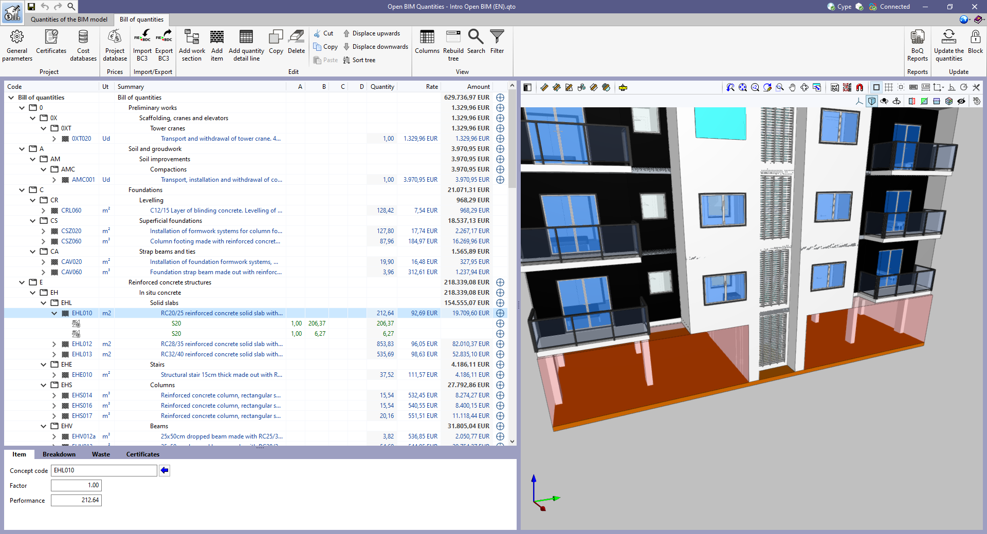
In order to use the measurements in the project's bill of quantities in a simple way, a button with a blue arrow has been added to the editing panel of the detail lines next to the editing window of each variable (A, B, C and D). Clicking it will assign the value of the measurement made on the work area to the variable.

The option to "Zoom" into the 3D model element has been added in the following cases:

  • "Quantities of the BIM model" tab in Open BIM Quantities
    In previous versions, users could frame a component of the IFC model in the 3D view. The same can now be done for the different groups of elements (types, entities, structure, layers and groups).
  • "Bill of quantities" tab in applications
    In previous versions, users could frame the elements used in a quantity detail line of the bill of quantities in the 3D view. The same can now be done for items and work sections.

The "Font size" option has been added to the general configuration menu of the applications. This tool allows users to increase or decrease the basic size of the font used in the user interface of the programs. Thanks to this implementation, the accessibility of the applications has been improved while also ensuring the correct visibility of the content on devices with different screen resolutions.

To enter a "Basic size" the "Set custom font size" option must be checked. The size users can enter is the application's basic font size. Any other font sizes that may exist in the program's interface will be automatically modified proportionally according to the change in the basic size.

It is important to note that, as this is a common parameter, its modification will affect all installed CYPE tools.

A new example job has been added for an apartment block with 8 dwellings. In this building, based on the architectural model, the distribution of electrical mechanisms and lighting points is completed with the corresponding checks of the protection volumes in bathrooms and toilets, and the minimum provision in rooms.

CYPELEC Electrical Mechanisms version 2023.b now includes the possibility of automatically saving jobs every so often.

A new tool has been implemented in the user interface that is common in Open BIM applications with a 3D working environment. Now, the management of the elements from the digital model of the building, which comes from the associated BIMserver.center project, is carried out from the "Elements read" menu located in the left sidebar of the application. 

The elements read are structured in the form of a tree based on two classification types: "Models" and "Categories". The organisation by "Models" allows users to inspect each contribution linked to the job and each associated 3D model within it. On the other hand, the "Categories" group the "Elements read" into families according to their features. Next to each tree component, three buttons are displayed to control the visibility, the display mode (solid, transparent or wire) and the object snap. It should be noted that the organisational settings applied to the organisation by "Models" prevail over those indicated by "Categories".

Applications can have default visibility and object snap settings when creating a new view. Furthermore, when entering new components with the tools in the program, the application itself can force the activation or deactivation of the visibility and object snaps of certain categories. When this happens, a yellow padlock will be displayed next to the set options. When users finish using the tool, the tree will return to its original state.

In previous versions, the management of the visibility of BIM project models was carried out in the configuration panel of a view. As a consequence of this improvement, editing is now managed from the "Elements read" menu in the left sidebar and has therefore been removed from the previous location. However, in the editing panel of a view users can indicate whether the view should have its own configuration for viewing these elements or whether it should use the general configuration of the job. For this purpose, the "Use a specific view configuration for the view" option has been added. When this option is active, the "View" text will appear in the "Elements read" menu.

In addition to the component tree of the external models, the "Elements read" menu includes a toolbar with a group of buttons that allow the following actions to be carried out:

  • Isolate selection
    Allows elements from the 3D model to be isolated. Users can select the elements of the 3D model that they wish to isolate and when right-clicking on them, the rest of the elements from the model will disappear.

  • Hide
    Allows the selected elements to be hidden. Users can select the elements from the 3D model that they wish to hide and by right-clicking on them, they will disappear.

  • Show all
    Shows all hidden elements.

  • Aspect
    Allows users to choose between normal drawing or monochrome drawing.

  • BIM information
    Displays a panel showing the attributes associated with the selected component.

In version 2023.a, the management of visibility and object snaps of external elements is available in the following CYPE Open BIM applications:

  • CYPE Architecture
  • CYPELEC Distribution
  • CYPELEC Electrical Mechanisms
  • CYPELEC PV Systems
  • CYPEPLUMBING Water Systems
  • CYPETHERM RE2020
  • CYPEURBAN
  • Open BIM Analytical Model
  • CYPE Construction Systems
  • Open BIM COVID-19
  • CYPE Lightning
  • Open BIM Sampling
  • Open BIM Site

The number of electrical symbols that users can select for normal (wall or ceiling) lighting points, emergency lighting and sockets is extended.

Mechanisms can now be introduced in a horizontal position to be placed on technical floors, worktops or furniture.

CYPELEC Electrical Mechanisms changes from a 2D environment to a new 3D work environment, achieving greater capacity in the architectural modelling of terminal elements in electrical and telecommunications installations.

The new 3D work environment provides:

  • Greater geometric precision when positioning ceiling lighting points, wall lighting points, emergency lighting and electrical mechanisms: switches, multiway switches, sockets, audiovisual connectors and telephone connectors.
  • Improvement in the connection of lighting circuits and points of use between switches and lighting points, including those in stairwells between floors.
  • Improvement in the representation of electrical zones in rooms containing a bath or shower.
  • Improvement in the requirements for placing sockets in proximity to electrical appliances.

The possibility of selecting a multiple socket base to power the equipment imported from the BIM model has been added.

A new feature is added to the program that allows users to both manually and automatically assign outlets to the equipment imported from the BIM model.

When reading a BIM project, CYPELEC Electrical Mechanisms allows electrical equipment included in the architectural model to be imported, such as: televisions, cookers, washing machines, dishwashers, extractor fans, refrigerators, microwaves and computers.

The program will notify users when the required service needs to be provided for this equipment. This service can be carried out by means of a manual or automatic assignment of the previously introduced required outlet, or by means of an automatic generation of outlets, according to the criteria for the selection of outlets per appliance.

  • Manual assignment with previously introduced outlets
    In order to carry out this manual assignment, users must click on the “Assign” button in the “Assign outlets” group in the toolbar and in this order. First, the equipment is chosen, and then the outlet to be assigned.
  • Automatic assignment with previously introduced outlets
    In order to carry out this automatic assignment, users must click on the "Generate" icon in the "Assign outlets" group in the toolbar. The program will select the one that is best suited for service and proximity from those available.
  • Automatic generation of outlets per equipment
    In order to carry out this automatic generation, users must click on the “Generate outlets” icon in the “Elements” group in the toolbar. The program will introduce the outlets required depending on the service required for each device.  The criteria for their introduction depends on the selection made in the "Processing of the equipment of the BIM model" section of the general options.

When elaborating electrical drawings, an option has been added that allows users to create drawings of the 2D views in vector graphics format. These drawings can be generated in DXF and DWG file formats.