Update history​​

CYPETEL Wireless

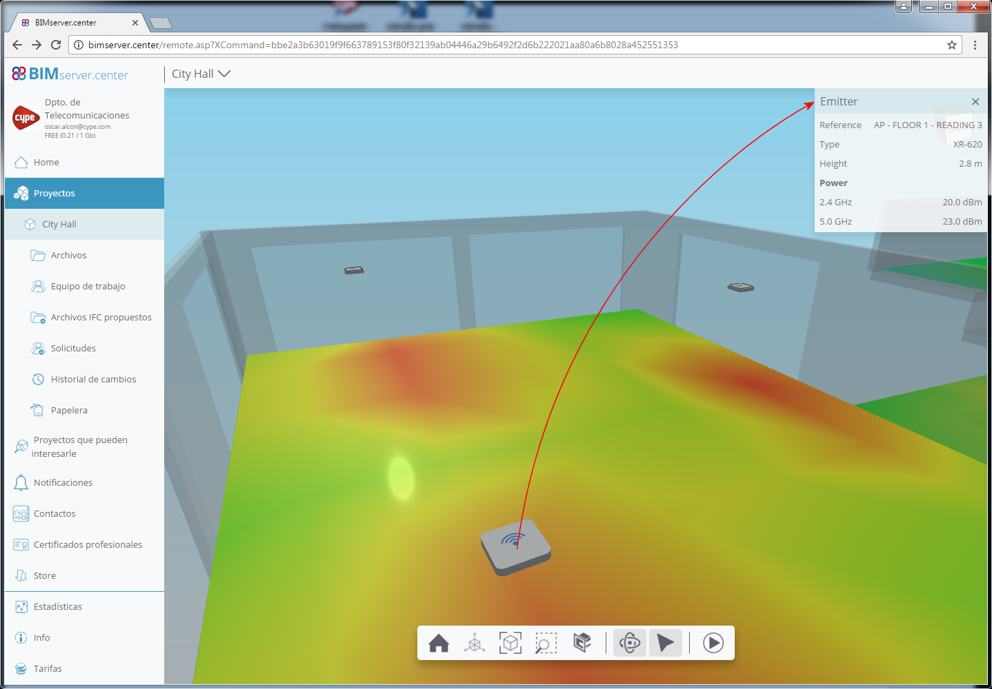
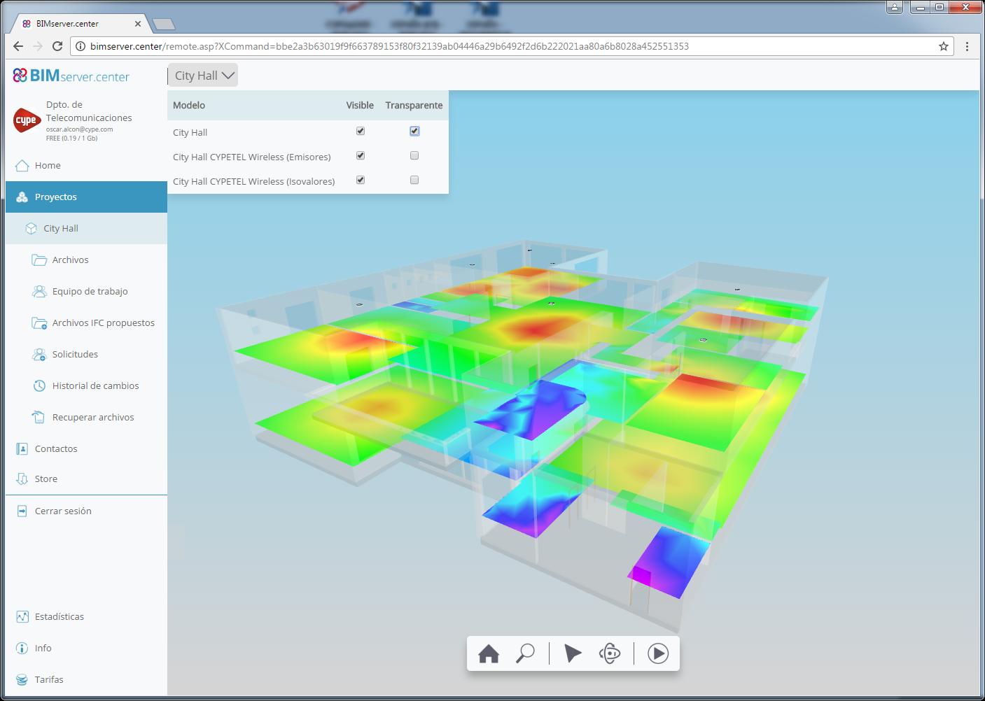
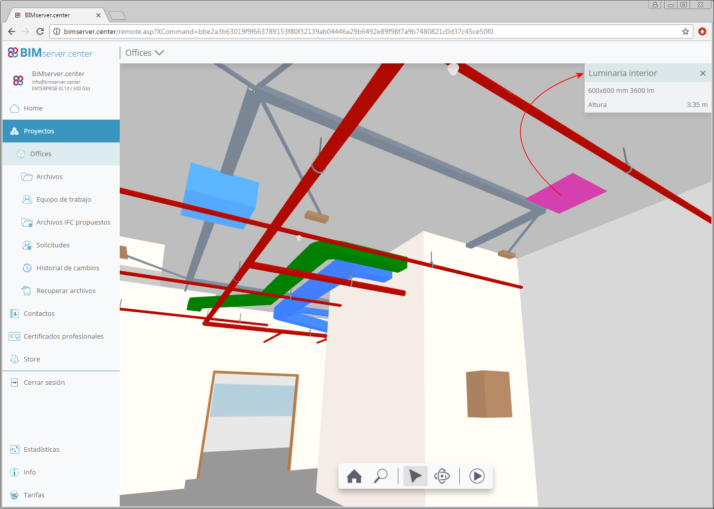
As of the 2019.a version, CYPETEL Wireless exports data from the wireless network to the file with “.GLTF” extension, used to show the 3D model in the integrated viewer in BIMserver.center and in its application for mobile phones. Thanks to this new feature, the collaborators of the BIM project can obtain the following information on the emitters that have been selected for the project:

  • Reference of the emitter
  • Type of emitter
  • Installation height
  • Transmission power

The possibility to obtain a 3D view of the radiation diagrams of the emitters. Furthermore, for each receiver, it is possible to see where the radiation diagram of each associated emitter is directed towards.

The 2018.l version of CYPETEL Wireless includes the possibility to vary the azimuth and elevation angles of emitter antennas. This allows users to define the direction of the radiation diagram depending on the requirements of the installation.

Thanks to the inclusion of iTCalc in the Open BIM workflow (software that exports the position of telecommunication inlets to the BIM project), CYPETEL Wireless positions the copper pair cable inlets on the floor plans to assist users when configuring their wireless network (as well as displaying them in the 3D view of the BIM model, as occurs with all the programs included in the Open BIM workflow).

As of the 2018.l version, CYPETEL Wireless has an assistant, which has been created to help define attenuation values of construction elements. The assistant allows users to import attenuation data of different predefined construction elements.

A new project called “Detached house” has been included, where users can view an example of a designed installation.

The information contained in the results reports, for each receiver point, has been redistributed for a better understanding of the calculations that have been carried out.

The design process has been optimised and can now design several emitters simultaneously, thus considerably reducing the time required to perform the analysis.

Design options have been added, which allow users to define the influence emitters have on receivers on other floors, specifying the elements to be considered in the analysis.

The 2018.k version has incorporated checks to warn users of incorrectly defined heights for emitters and work planes with respect to the height of the space.

As of the 2018.k version, users can define the radiation gain and diagram of the emitter antenna, for each frequency band. The program also incorporates an assistant to help users to import the properties of different predefined types of antennas.

When a project that has been designed using CYPETEL Wireless is exported to the project located in the “BIMserver.center” platform, the IFC file that is generated includes a “GLTF” file with the coverage contour maps in the 3D view. This allows users to view the diagram with the 3D viewer of “BIMserver.center” using the Web version or application for mobile devices (App).

This “GLTF” file is independent to that generated by CYPETEL Wireless with emitters, so each file can be viewed independently.

3D viewer

Since the 3D view in “GLTF” format was implemented in the 2018.i version of programs that are integrated in the Open BIM workflow, 3D models can be viewed using the viewer that is integrated in the BIMserver.center web platform and using the application (App) for mobile devices.

As of the 2018.k version, the information that is exported to the 3D viewer of BIMserver.center is increased for the following CYPE programs:

Documents and drawings

As of the 2018.k version, the following CYPE programs incorporate more documents to BIM projects located in the BIMserver.center platform:

  • CYPELUX, CYPELUX CTE, CYPELUX RECS, CYPELUX LEED y CYPELUX HQE
    The drawings that are elaborated by these applications are exported as documents attached to the IFC file. More information can be found in the “Export drawings to the BIM project” section.


  • CYPELUX LEED y CYPELUX HQE
    The justification reports of each certification and the drawings of the project are exported. More information can be found in the “Export drawings and documents to the BIM project” section.