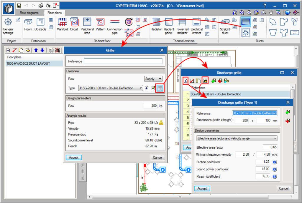
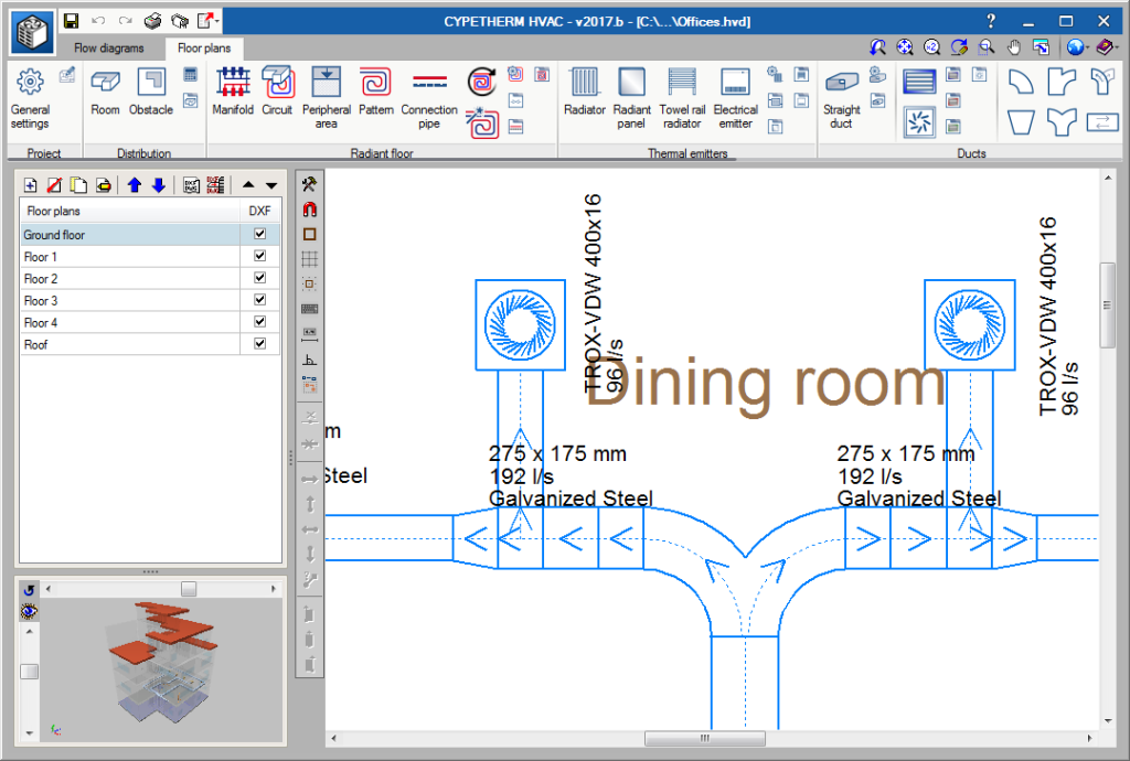
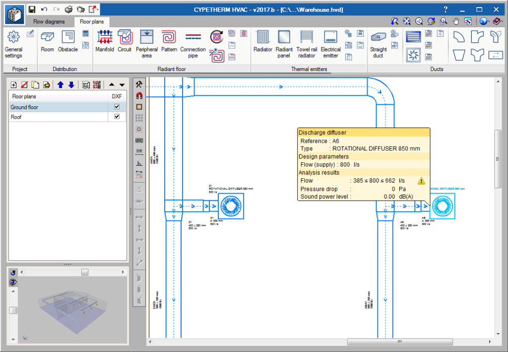
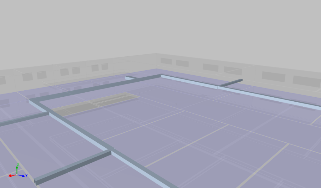
An additional method is included in the 2017.b version to introduce grille manufacturer libraries. This way, users can introduce the manufacturer library whether it only provides the dimensions of the grilles or also the allowable flow or pressure ranges and noise level. Once the library has been introduced, when the grille is introduced, it will be assigned a flow and the remaining values will be found by interpolation.
Update history
- Solutions
- CYPETHERM HVAC
- Update history
CYPETHERM HVAC
Pressure loss accumulated by networks
In the previous version (2017.a) the new feature to design air-duct networks using air flow drag from grilles to the initial span of the network was implemented.
Now, in the 2017.b version, the program detects the critical path to the worst-case grille and provides the value of the total pressure loss. The report displays the networks in order, with the spans that correspond to the critical path first. Furthermore, any connection elements used are displayed in the report (elbows, transformations and branches) with their associated pressure loss and in order of appearance.
Flow range warnings
The program places a yellow warning triangle when a grille or diffuser has a flow that lies outside its operating range. This way, users can decide whether to choose another with a different size, add a terminal and redistribute the flows or hide the warning when they consider that the flow lying outside the range is negligible (e.g. 1 l/s).
Users can now define chillers and heat pumps. As well as their graphical representation on drawings, their main technical properties can be defined (air or water condensation, 2 or 4 tubes, operation temperature).
Similarly, the program provides the association of the power required by the water meters of the systems (air conditioners, fan coil groups) to obtain the total sum of the power that is required.
The total area of rectangular ducts, total length of circular ducts by diameters, as well as the number of grilles of each type have been incorporated in the quantities report.
Implemented in the 2017.a version is the design of air ducts using air flow drag from the grilles to the initial span of the network.
Air discharge, return and extraction grilles can be defined. The program allows users to define libraries, where each grille is defined with a reference, dimensions and range of allowable flows, amongst other properties.
The grilles are incorporated in the floor plan and each one can be assigned an air flow corresponding to the design results. The program will emit a warning if the assigned flow is excessive or insufficient.
The design has been implemented of some parameters of radiant floor installations such as discharge temperatures in manifolds (which will be shared by all the circuits connected to each manifold) and the thermal jump of each circuit, with the aim to adjust the power provided by each circuit to that required by the installation.
The 2016.m version implements the analysis and design of radiant panels, towel rail radiators and electrical emitters. All these are exported to IFC (3D view).
Furthermore, in the case of electrical emitters, their electric load is also exported so it may be considered in CYPELEC REBT (CYPELEC spanish version) , CYPELEC NF (CYPELEC french version) or other programs that import IFC files.

The 2016.m version of CYPETHERM HVAC designs connection elements between air ducts. The program also designs the load losses generated by these elements in accordance with ASHRAE’s standard fittings tables. The connection elements contemplated in the 2016.m version are:
- Circular and rectangular elbows
- Rectangular-rectangular, circular-circular size transformations
- Transformations between rectangular-circular and circular-rectangular ducts.
The program displays:
- A panel to consult the detailed calculations of each element
- The 3D view in the BIM model
- A results table
As of the 2016.l version, CYPETHERM HVAC generates files in IFC format containing the ducts that have been introduced and designed by the program, so that any related Open BIM workflow program can view them in the 3D view.
More information on the Open BIM workflow proposed by CYPE can be found on the section: Open BIM technology as a project tool of the new features of the 2016.k version.
As of the 2016.l version, CYPETHERM HVAC allows users to carry out the design and analysis of air ducts by defining the following parameters:
- The material of the duct from the library (galvanised plate, fibre)
- The standard size and shape (rectangular or circular) of the duct (International System and Imperial System)
Once the analysis and design procedures have been completed, CYPETHERM HVAC provides:
- On-plan representation of the straight span
- Consultation panel containing the detailed calculations of the span
- Results table
The analysis and design of air ducts is included in the “Air conditioning ducts” module, used in CYPETHERM HVAC.

