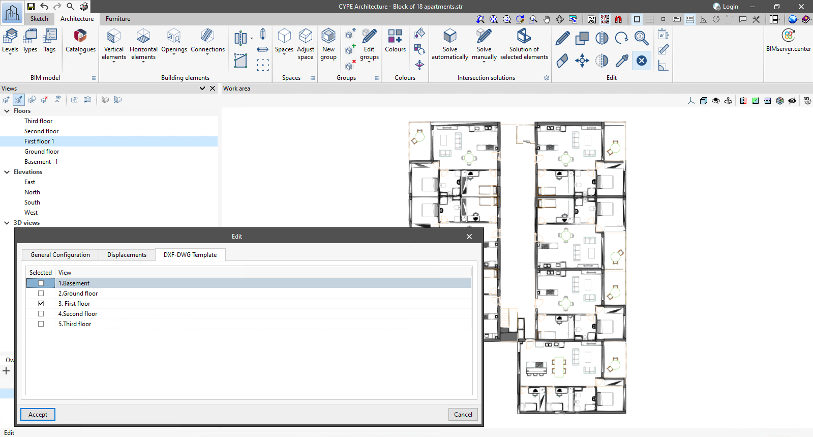
Update history​

Open BIM Analytical Model

Font size

The "Font size" option has been added to the general configuration menu of the applications. This tool allows users to increase or decrease the basic size of the font used in the user interface of the programs. Thanks to this implementation, the accessibility of the applications has been improved while also ensuring the correct visibility of the content on devices with different screen resolutions.

To enter a "Basic size" the "Set custom font size" option must be checked. The size users can enter is the application's basic font size. Any other font sizes that may exist in the program's interface will be automatically modified proportionally according to the change in the basic size.

It is important to note that, as this is a common parameter, its modification will affect all installed CYPE tools.

Reading the edges defined in the IFC model

The "Use the edges defined in the IFC model" option has been added to the configuration panel for the automatic generation process of the analytical model. When activated, instead of detecting the edges of the analytical model from the generated analytical surfaces, the edge definition of the geometric model will be used directly when available. In order to use this method, users must first select the "Use the outlines of the spaces defined in the IFC model" option.

The IFC Builder application currently exports the edges of its geometric model in the standard IFC format. Thanks to this new feature, all the analytical information generated by both tools can be read in Open BIM Analytical Model.

Reading the analytical models of the BIMserver.center project

As of version 2023.c, Open BIM Analytical Model can read the analytical models of the BIMserver.center project contributions. This way, a new analytical model does not need to be redefined from scratch in Open BIM Analytical Model.

By using the "Analytical model" option available from the "Generate" group in the toolbar, users can choose between two different generation methods as long as there are analytical models of the BIMserver.center project that already exist and have been read:

  • Import an analytical model of the project
    A list is displayed with the analytical models of the project contributions that have been read in the application. Selecting one of them will import its components into the current job. The model reference is the name of the contribution.

  • Generate the analytical model based on the architectural model
    The options for the automatic generation process of the analytical model from a geometric model are displayed, as in previous versions. This is the method that should be used if no analytical models have been read from the BIMserver.center project.

Other improvements and corrections

Open BIM Analytical Model version 2023.b includes the following improvements and corrections of the program for certain cases:

  • Deselecting an adjacent surface
    Adjacent surfaces can now be deselected in the configuration panel of an analytical model surface adjacent to "Surface".

  • Checking adjacent surfaces
    In previous versions, the "The adjacent surface is not defined" check was treated as an error message, it is now a warning.

  • Check for elements of the physical model
    The "No analytical surface has been defined for an element of the physical model" is now unchecked by default.

  • Opening detection
    Opening detection in the automatic analytical model generation process has been improved.

  • "External environment" type spaces
    A problem that could cause warnings on external analytical surfaces due to the "A valid volume must be defined for the space" volume check being carried out in "External environment" type spaces has been corrected.

  • Joining surfaces
    An error that could occur when using the "Join surfaces" tool with more than two surfaces of the analytical model has been corrected.

  • Generating an opening on an analytical surface
    An error that could occur when using the "Generate an opening in an analytical surface based on an opening of the physical model" tool has been fixed.

Tool for combining spaces

The "Group spaces" tool has been added to the list of spaces in the analytical model and is available via the "BIM Model" button on the toolbar. By running it, users can choose several spaces and the application will group them into a single space, which will contain all the surfaces and edges of the selected spaces. Furthermore, the surface area and volume values of the new space will be calculated.

This tool is particularly useful for spaces that are entered independently in the architectural model but are connected and, therefore, form a single analytical space.

Managing the visibility and object snaps of external elements

A new tool has been implemented in the user interface that is common in Open BIM applications with a 3D working environment. Now, the management of the elements from the digital model of the building, which comes from the associated BIMserver.center project, is carried out from the "Elements read" menu located in the left sidebar of the application. 

The elements read are structured in the form of a tree based on two classification types: "Models" and "Categories". The organisation by "Models" allows users to inspect each contribution linked to the job and each associated 3D model within it. On the other hand, the "Categories" group the "Elements read" into families according to their features. Next to each tree component, three buttons are displayed to control the visibility, the display mode (solid, transparent or wire) and the object snap. It should be noted that the organisational settings applied to the organisation by "Models" prevail over those indicated by "Categories".

Applications can have default visibility and object snap settings when creating a new view. Furthermore, when entering new components with the tools in the program, the application itself can force the activation or deactivation of the visibility and object snaps of certain categories. When this happens, a yellow padlock will be displayed next to the set options. When users finish using the tool, the tree will return to its original state.

In previous versions, the management of the visibility of BIM project models was carried out in the configuration panel of a view. As a consequence of this improvement, editing is now managed from the "Elements read" menu in the left sidebar and has therefore been removed from the previous location. However, in the editing panel of a view users can indicate whether the view should have its own configuration for viewing these elements or whether it should use the general configuration of the job. For this purpose, the "Use a specific view configuration for the view" option has been added. When this option is active, the "View" text will appear in the "Elements read" menu.

In addition to the component tree of the external models, the "Elements read" menu includes a toolbar with a group of buttons that allow the following actions to be carried out:

  • Isolate selection
    Allows elements from the 3D model to be isolated. Users can select the elements of the 3D model that they wish to isolate and when right-clicking on them, the rest of the elements from the model will disappear.

  • Hide
    Allows the selected elements to be hidden. Users can select the elements from the 3D model that they wish to hide and by right-clicking on them, they will disappear.

  • Show all
    Shows all hidden elements.

  • Aspect
    Allows users to choose between normal drawing or monochrome drawing.

  • BIM information
    Displays a panel showing the attributes associated with the selected component.

In version 2023.a, the management of visibility and object snaps of external elements is available in the following CYPE Open BIM applications:

  • CYPE Architecture
  • CYPELEC Distribution
  • CYPELEC Electrical Mechanisms
  • CYPELEC PV Systems
  • CYPEPLUMBING Water Systems
  • CYPETHERM RE2020
  • CYPEURBAN
  • Open BIM Analytical Model
  • CYPE Construction Systems
  • Open BIM COVID-19
  • CYPE Lightning
  • Open BIM Sampling
  • Open BIM Site

Other improvements and corrections

Version 2023.a of Open BIM Analytical Model includes other minor improvements and corrections of the program for certain cases:

  • Inserting an opening in an analytical surface
    When inserting an opening on an analytical surface, the surface containing the opening was assigned as the element in the opening. This has been fixed in version 2023.a.

  • Modifying the points of an opening
    A problem that occurred when modifying the points of an opening has been fixed. The program did not allow the surface containing the opening to be redrawn. Although this was not an analysis error, it generated a strange effect in the 3D model.

  • Generating analytical spaces
    An error that could appear when generating the analytical spaces during the automatic generation process of the analytical model has been fixed.

  • Adjacencies of the analytical surfaces
    An error that could occur when determining the adjacencies of analytical surfaces during the automatic generation process of the analytical model has been fixed.

  • Entering an opening with the “Orthogonality” tool
    Orthogonality can now be used when entering an opening into a surface of the analytical model.

Tool for generating an opening in an analytical surface from an opening in a physical model

The "Generate an opening in an analytical surface based on an opening of the physical model" option has been added to the "Elements" group of the Open BIM Analytical Model toolbar. When using this feature, an opening from the physical model and a surface from the analytical model can be selected. Based on the geometry of the opening, the program will create an opening in the selected surface and a new surface with the "element in opening" attribute at the position of the opening.

Tool for assigning the properties of a surface of the physical model to an analytical surface

The "Assign the properties of a surface of the physical model to an analytical surface" option has been added to the "Elements" group in the Open BIM Analytical Model toolbar. When selecting an analytical surface with this feature, a list of all available construction elements is displayed. Users can choose one of them and its properties will be assigned to the surface. If the application detects that a component of the physical model may correspond to the analytical surface, it will be marked by default.

This tool is also available from the editing panel of a surface. In this case, a blue arrow icon has been added next to the surface reference. Clicking on it will display the list of available construction elements.

Tool for generating analytical surfaces from the 3D contour of a space in the physical model

The "Generate analytical surfaces based on a space of the physical model" option has been added to the "Elements" group in the Open BIM Analytical Model toolbar. This feature allows users to obtain the surfaces outlining a space from the physical model and creates the equivalent analytical surfaces. The space will also be added to the analytical model and all generated surfaces will be assigned to that space.

Improved entry of surface points

When entering an analytical surface in previous versions of Open BIM Analytical Model, all of its points needed to be coplanar. Now, the first three points inserted into the work area determine the surface plane, while the rest are projected onto said plane. This makes it much easier to enter new surfaces by means of the template snap from the physical model.

New warning and error system

A new project review process has been implemented to detect possible inconsistencies in the analytical model and, thus, make it easier for the user to solve them. To do so, the following options have been added to the "Errors" group in the application toolbar:

  • Checking errors
    Runs the error checking in the project. This check is also performed at the end of the automatic analytical model generation process.

  • Checks
    Displays the configuration panel where the checks to be carried out in the project are established. A distinction is made between errors and warnings occurring on components of the physical model and those relating to the analytical model. For the physical model, certain elements can be excluded from the analysis. Some checks are not active by default as they require longer analysis times; these are displayed in the panel with a warning symbol.

  • Show/Hide incidents
    If this option is activated, elements where an issue has occurred will be highlighted. If it is an error, a red circle will appear next to the component; if it is a warning, a yellow triangle will appear. When the mouse pointer is positioned over the symbol, the message describing the error will be displayed. If the incident occurs on an analytical surface, it will change colour (red when it is an error and yellow when it is a warning) to help identify the affected object.