Update history
Open BIM Layout
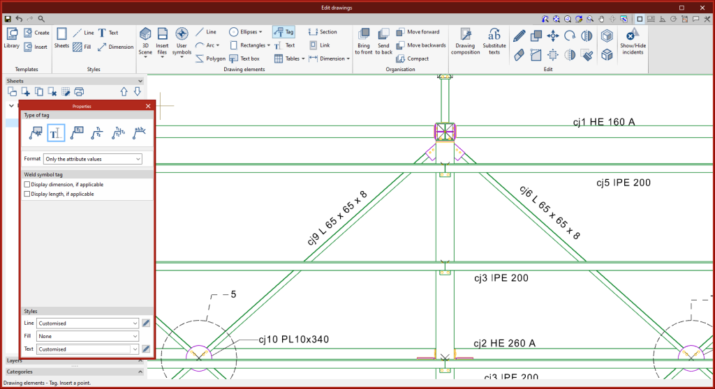
Text-only tag
- Published on
- 2023.d
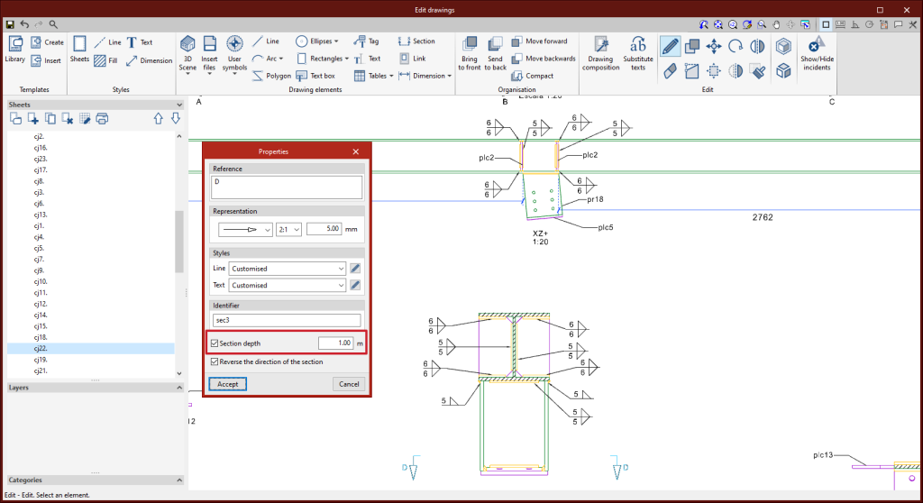
Section depth editing
- Published on
- 2023.d
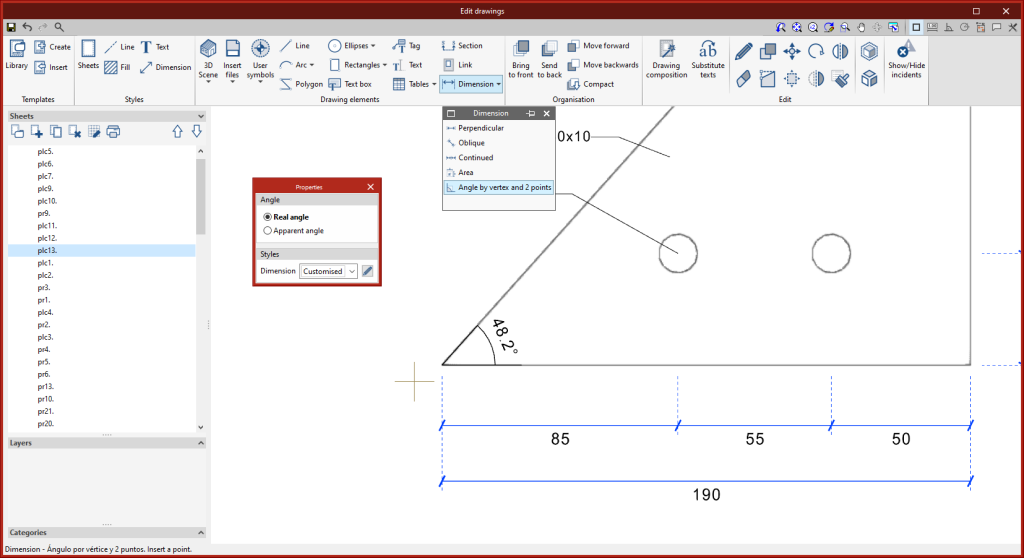
Angle dimensioning
- Published on
- 2023.d
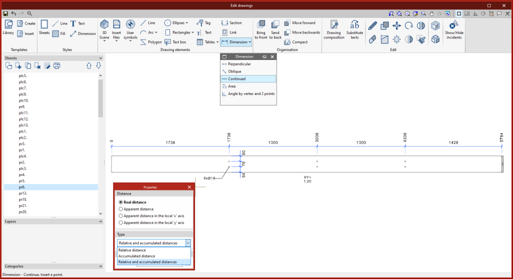
Continuous dimensioning
- Published on
- 2023.d
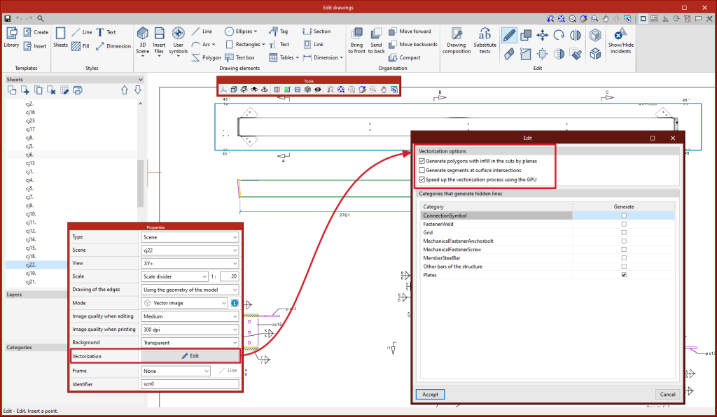
Drawing hidden lines
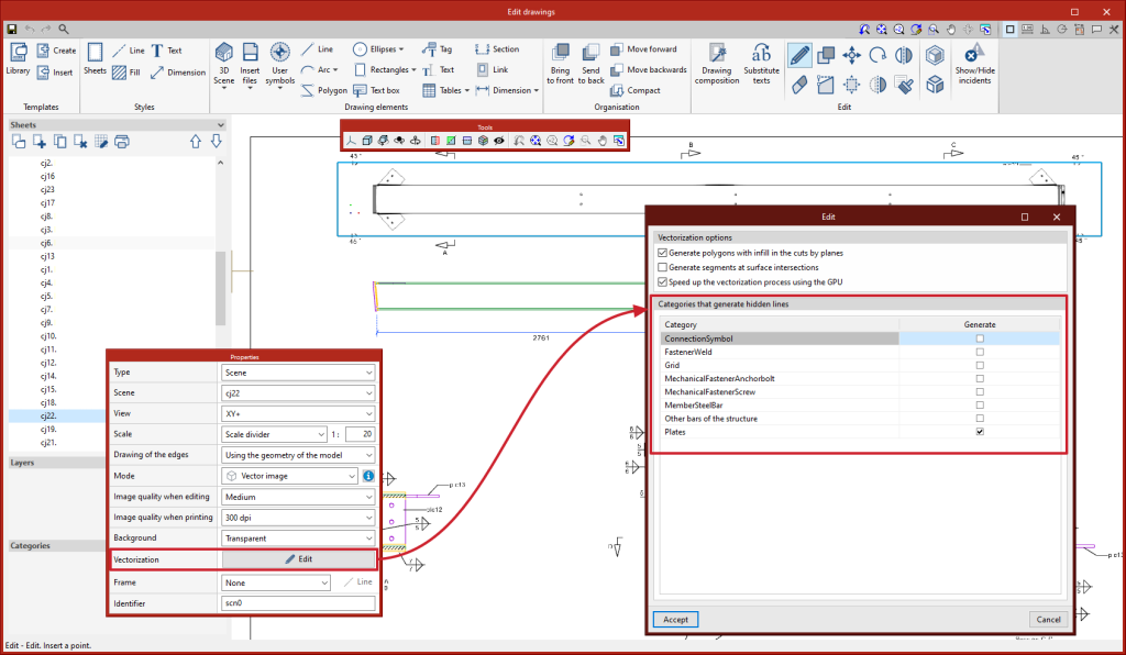
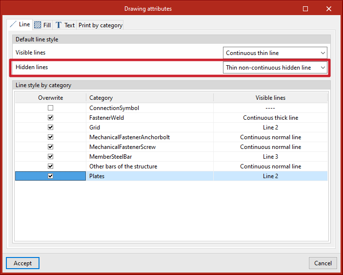
Hidden lines can now be drawn in scenes. Users can select the categories of elements that generate hidden lines in each scene from the editing panel of the "Vectorization" option.
- Published on
- 2023.d
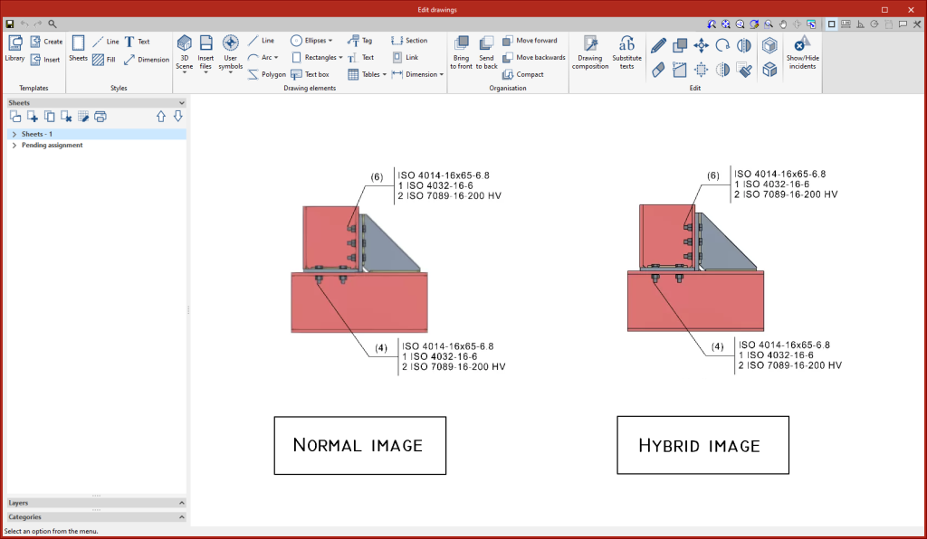
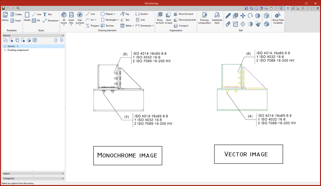
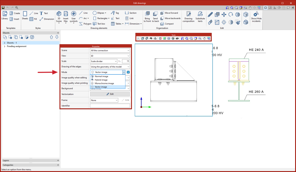
New scene drawing modes: "Vector image" and "Hybrid image"
In previous versions, the Open BIM Layout, StruBIM Steel and CYPE Connect programs had the following scene drawing modes: "Normal image" and "Monochrome image". As of version 2023.d, two additional modes have been added:
- Hybrid image
Image with coloured elements and edge vectors. - Vector image
Image without colour fill of the elements, with vector lines.
- Published on
- 2023.d
Font size
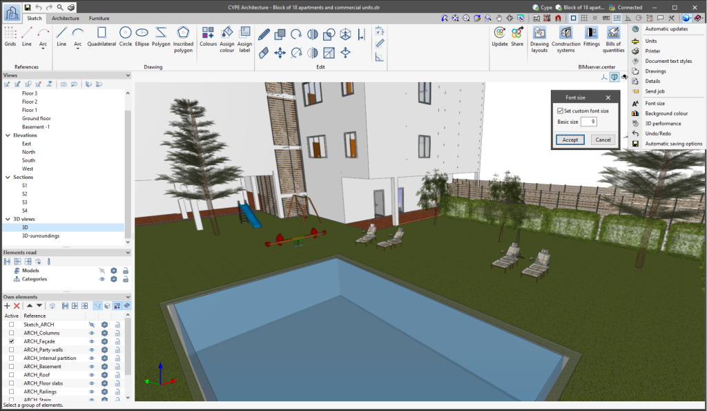
The "Font size" option has been added to the general configuration menu of the applications. This tool allows users to increase or decrease the basic size of the font used in the user interface of the programs. Thanks to this implementation, the accessibility of the applications has been improved while also ensuring the correct visibility of the content on devices with different screen resolutions.
To enter a "Basic size" the "Set custom font size" option must be checked. The size users can enter is the application's basic font size. Any other font sizes that may exist in the program's interface will be automatically modified proportionally according to the change in the basic size.
It is important to note that, as this is a common parameter, its modification will affect all installed CYPE tools.
- AcouBAT by CYPE, Arquimedes, CYPE 3D, CYPE Accessibility, CYPE Architecture, CYPE Connect, CYPE Connect Classic, CYPE Construction Systems, CYPE Cost Estimator, CYPECAD, CYPEFIRE, CYPEFIRE Hydraulic Systems, CYPEHVAC, CYPEHVAC Radiant Floor, CYPEHVAC Schematics, CYPELEC, CYPELEC Distribution, CYPELEC Electrical Mechanisms, CYPELEC Networks, CYPELEC PV Systems, CYPELUX, CYPEPLUMBING, CYPESOUND, CYPETEL Wireless, CYPETHERM EPlus, CYPETHERM LOADS, IFC Builder, Open BIM Analytical Model, Open BIM Layout, Open BIM Model Checker, Open BIM Quantities, Open BIM Site, Plugin Open BIM - Revit, Portal frame generator, StruBIM Box Culverts, StruBIM Cantilever Walls, StruBIM Deep Beams, StruBIM Embedded Walls, StruBIM Shear Walls, StruBIM Steel
- Published on
- 2023.d
New options bar for entering elements on the workspace
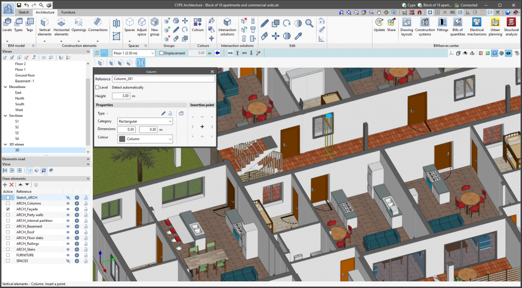
Since version 2020.f, applications with a 3D working environment include a floating toolbar to make it easier to enter or edit model components on the workspace. The options displayed in this toolbar depend on the active view and the element(s) being entered or edited.
This component is now anchored below the application toolbar. This makes better use of the available space in the user interface.
- Published on
- 2023.b
"Export BIM model" option in the connection between applications
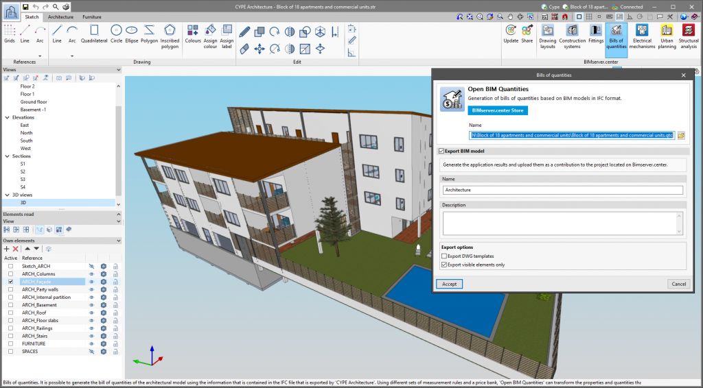
As of version 2023.b, Open BIM applications that have a direct link to other tools include the "Export BIM model" option. This option, which is active by default, allows users to decide whether to export the job information produced from the source application before opening the target application.
The possibility to skip the export process saves a significant amount of time when continuing the workflow in several different programs without making changes to the source application. However, it is important to note that if this option is deactivated and changes have been made, they will not be shared in the BIMserver.center project.
- Published on
- 2023.b
Exporting in FBX format
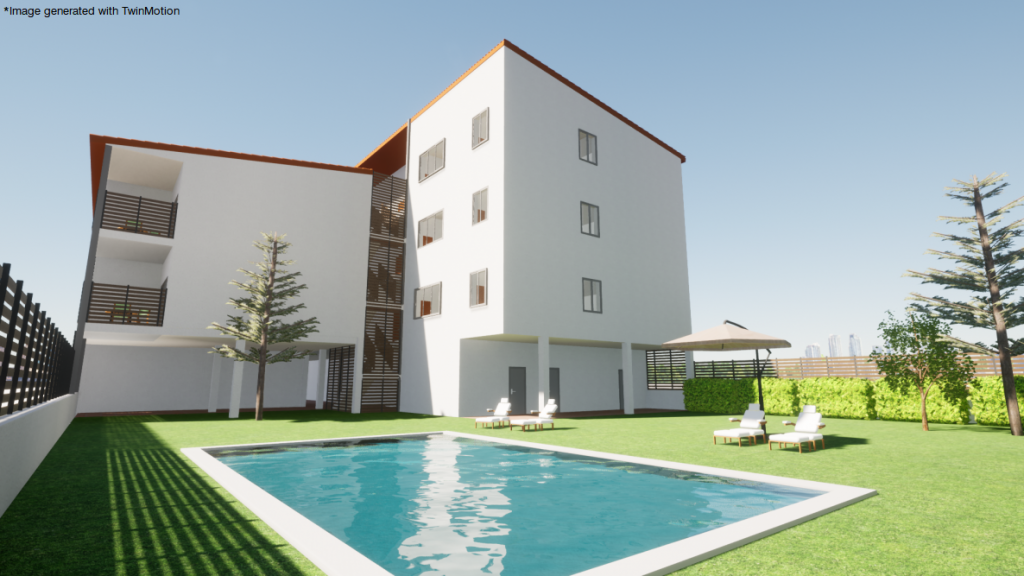
Version 2023.a of all CYPE programs that have the "Print/Save the current view" tool (usually all programs that display graphic information in a window) allows any generated 3D model to be exported in FBX format. This is one of the most common and accepted formats among rendering software (Twinmotion, Enscape, Sketchup+Vray, among others).
Exportation in FBX format is found in the dialogue box that opens when selecting the "Print/Save the Current View" button in any of the programs that include this tool. This feature allows users to export any element that is visible in the current window at that moment in FBX format (as well as elements that have been imported from other programs).
- Published on
- 2023.a
Dimension style
- Published on
- 2022.e
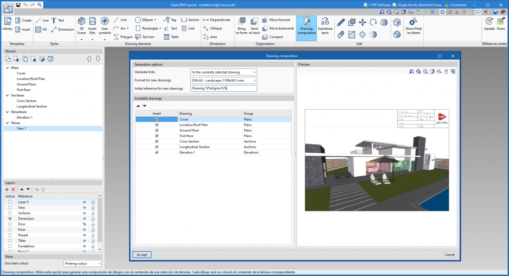
Automatic sheet composition
- Published on
- 2022.e

