Automatic model update during the editing of bars (linear elements) has been implemented. As of version 2023.d, once a bar has been edited, any affected connections will be updated automatically.

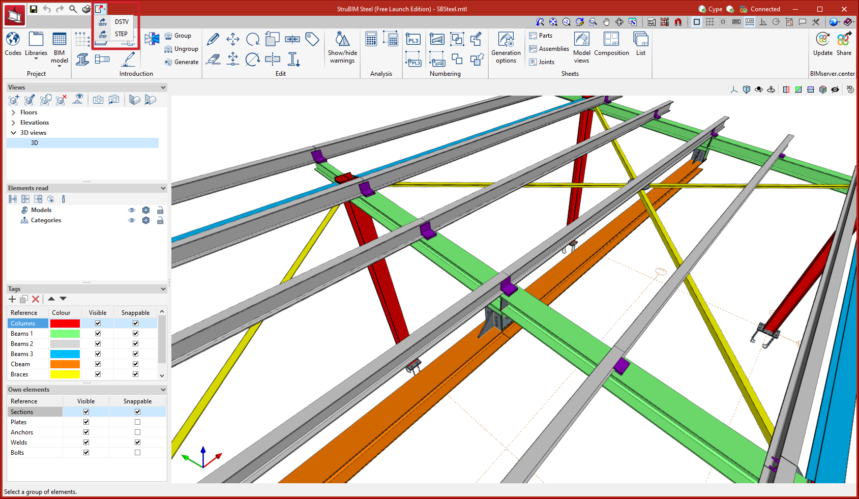
New menu option for exporting to DSTV and STEP formats
Up until version 2023.d, the options for exporting to DSTV and STEP formats were found in the "Share" tool located in the BIMserver.center tool group.
As of version 2023.d, these options are also available from the "Export" button at the top left of the screen.
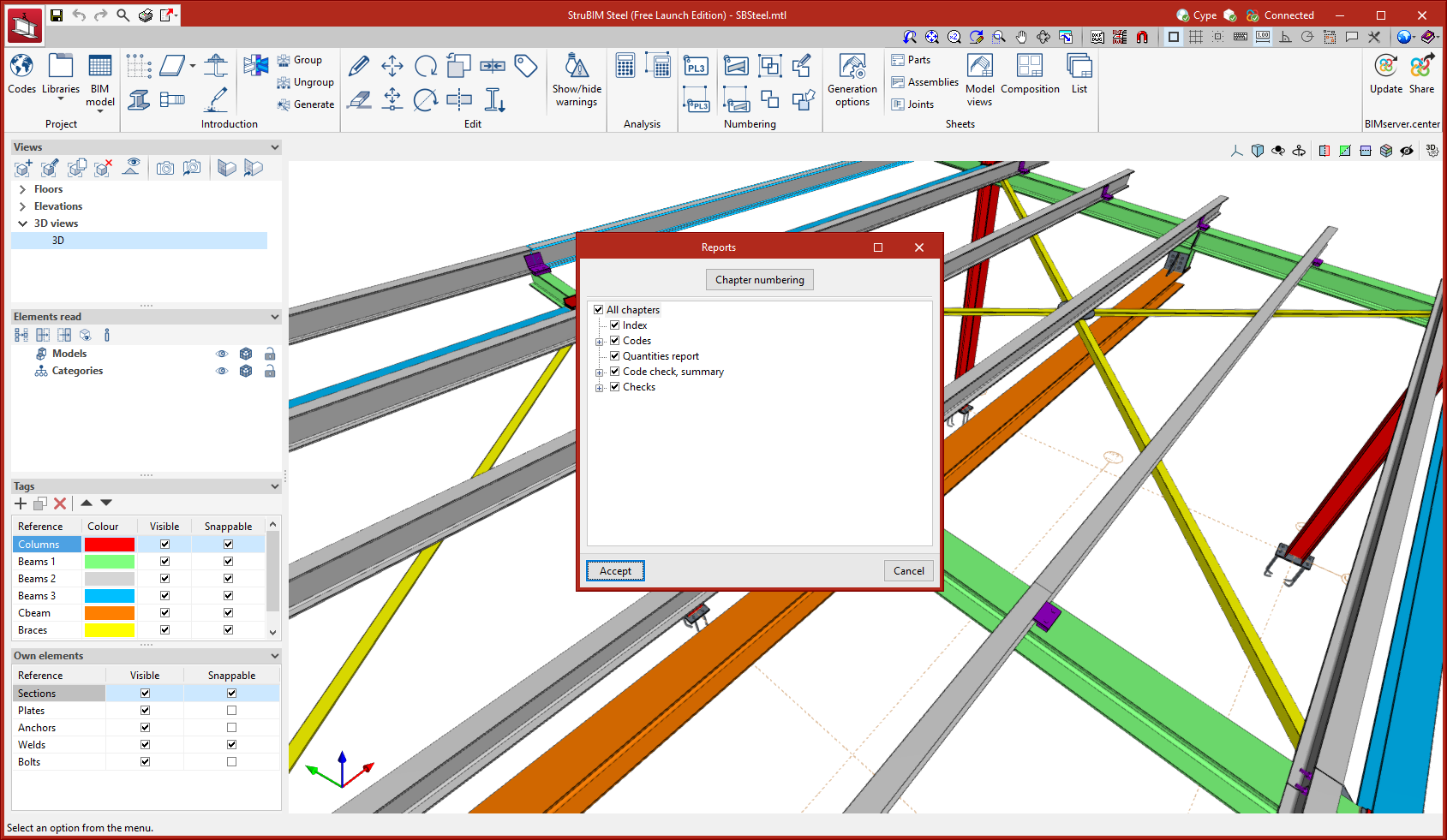
New report types
New report types have been added for connections:
- Codes
- Code check, summary
- Checks
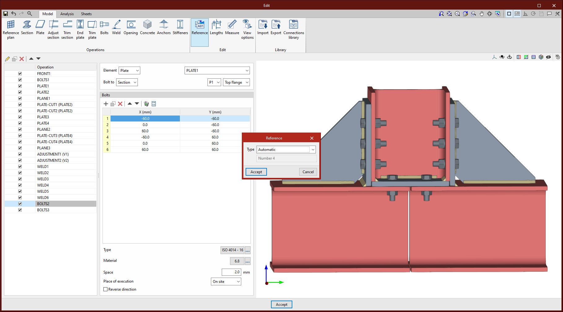
Editing the connection reference
A connection reference editing feature has been added. This reference can be either automatic or user-defined. The automatic reference is composed of the prefix defined in the sheet generation options.
Options for grouping and generating nodes
Options for managing groups of matching nodes have been added. Groups of nodes will be assigned the same connection.
The connection assigned to a group of nodes will read the bar forces from all the nodes in the group from the BIM project. The combination filtering carried out from "Generate from BIM model" is based on the sum of the combinations of all the nodes.
The options for managing these groups are:
- Group
Allows matching nodes to be grouped together. When a node is selected, all matching nodes will light up in yellow. - Ungroup
Allows previously grouped nodes to be ungrouped. - Generate connections
Generates nodes and groups them automatically if they match.

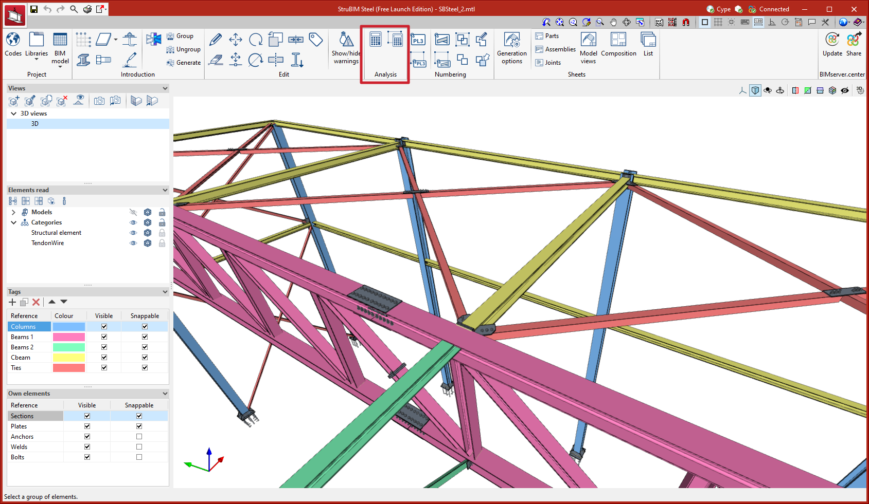
Analysing multiple connections
Two new options for analysing multiple connections have been added. These options, similar to those that were added in CYPE Connect version 2023.c, allow users to automatically analyse multiple connections without the need to access each connection to then click on the ''Stress/strain'' or ''Rotational stiffness'' analysis options:
- Analyse all the connections
Using this option, the program will analyse all the connections. - Analyse the selected connections
This option allows users to select the connections to be analysed.
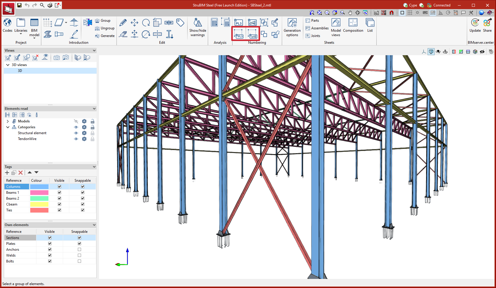
Tools for numbering a selection of elements
Two new tools have been added for numbering a selection of elements:
- Numbering a part selection
- Numbering an assembly selection
These tools only number selected elements, which allows users to number elements according to their own criteria, by floors, zones, phases, etc.
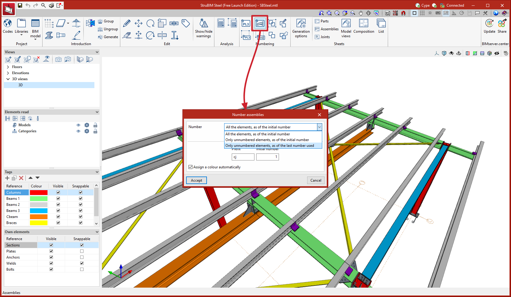
Numbering options
In version 2023.d the numbering tools for parts and assemblies have been improved. These tools search for matching elements and assign a number to them. With this new implementation, the grouping of equal elements is improved.
Three numbering options have also been added:
- Number “All the elements, as of the initial number”.
- Number “Only unnumbered elements, as of the initial number”.
- Number “Only unnumbered elements, as of the last number used”.

Rearranged option bar
The existing options together with the newly implemented tools are placed from left to right following the order in which they will commonly be used as the project develops.
Predefined connections, that existed until version 2023.c, will disappear in version 2023.d. From this version onwards, the connections between bars will be carried out using the “Connections” tool located in the "Introduction" menu.
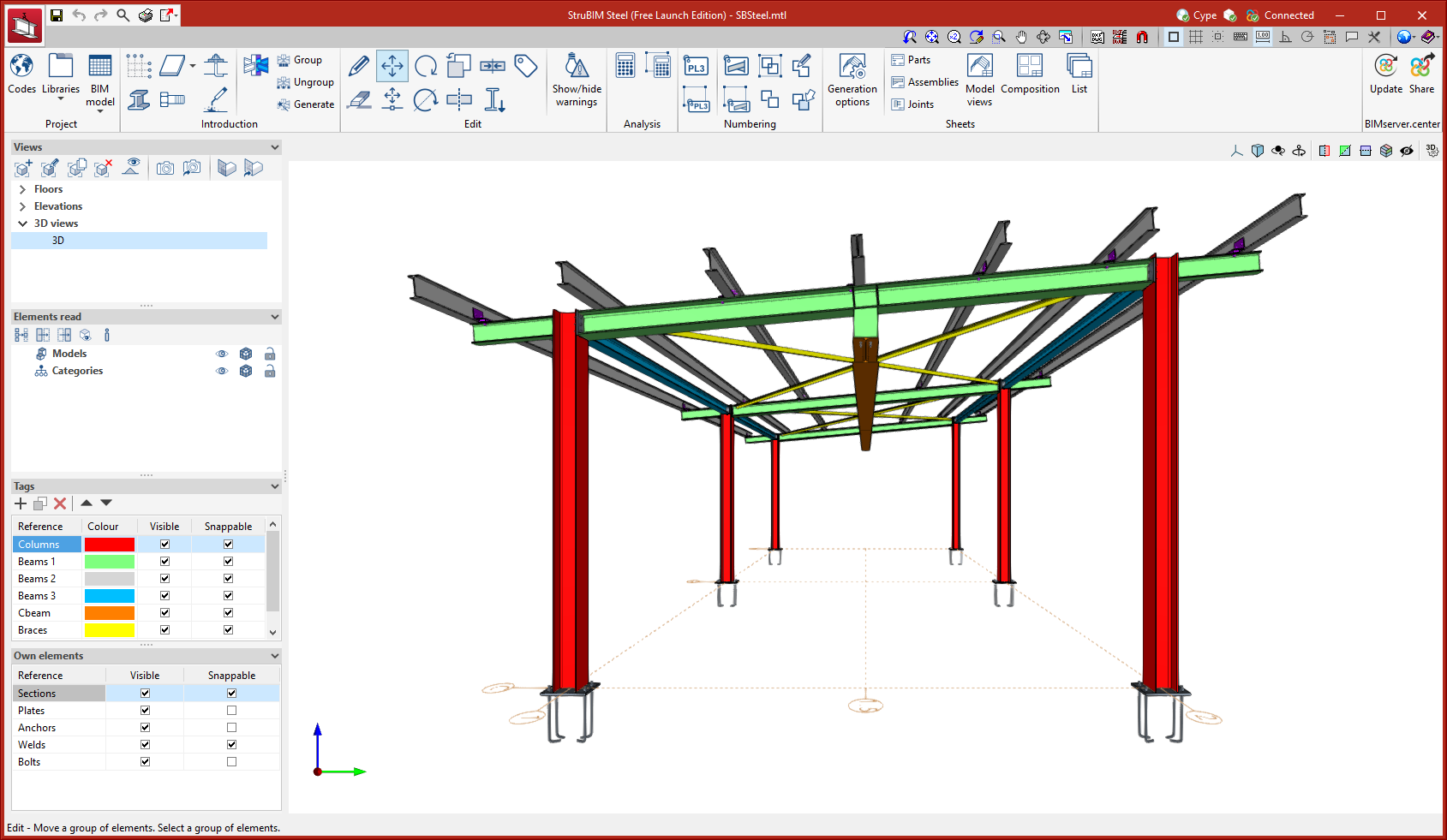
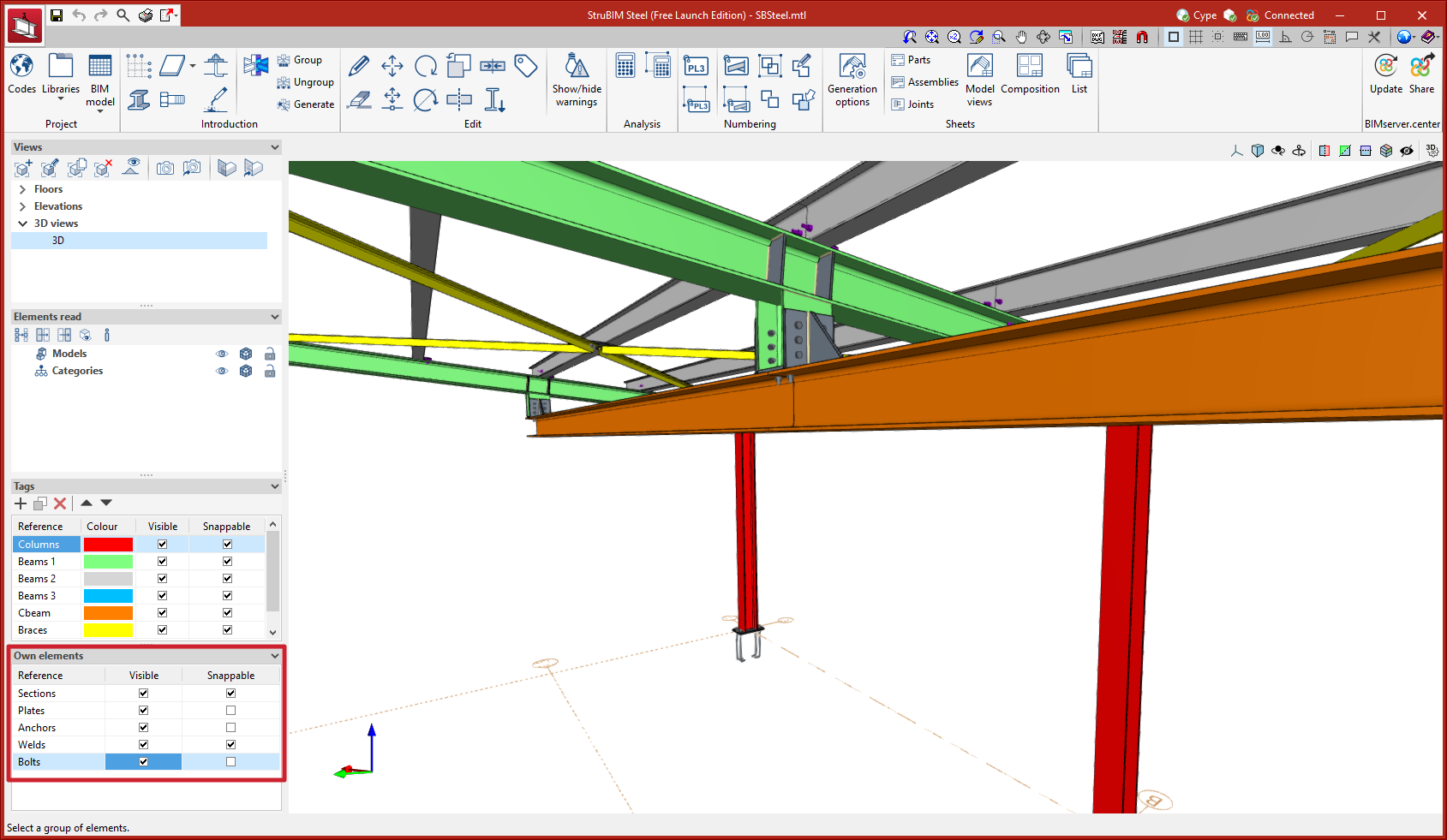
Managing visibility and snapping by elements from the sidebar
In previous versions, the management of visibility and snapping by elements was carried out by accessing a specific dialogue box from the options bar. As of version 2023.d, this management is located in the sidebar, allowing quick access to these commonly used tools.