
Manufacturer catalogue management
The "Project" group is located on the main toolbar of the "3D Model", "Diagrams: Analysis" and "Diagrams: Detail" tabs. From this group, you can access "Catalogues".


Catalogues
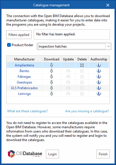
From the ‘Catalogues’ tool, you can:
- Manage manufacturer catalogues, with the aim of facilitating data entry into the project.
- Using the "Applied filters" option, you can apply filters when searching catalogues by category, language or country.
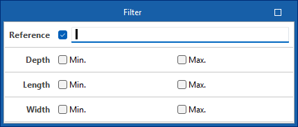
- From the "Product search" option, you can filter by dimensions and reference of infrastructure elements (cabinets/distribution boxes, junction boxes or manholes) or by product type and reference of telecommunications network equipment.
- From the "Other catalogues" option, you can download, update, or delete the catalogues included in the programme.
- Log in to Open BIM Database to download and use the information on manufacturer products available from the programs connected to this database free of charge.
Entering infrastructure elements into the BIM model
The main toolbar of the "3D Model" tab contains the "Infrastructure" group, which provides the tools needed to define the spatial position of telecommunications infrastructure elements in the BIM model through a 3D working environment. From this group, you can add the following elements to the installation:

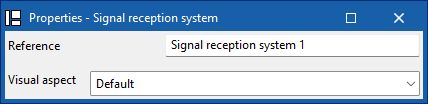
Signal reception system
Enter a signal reception into the BIM model and configure its display preferences.

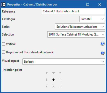
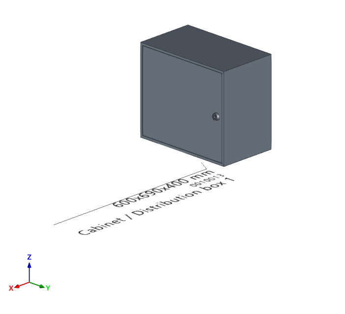
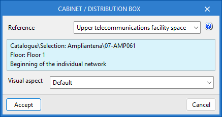
Cabinet/Distribution box
Enter a distribution cabinet or box from a manufacturer's catalogue, differentiate between the common part of the building and the private part, and set your display preferences. In addition, if the installation has several independent verticals, you can define the reference of the vertical to which this element belongs.
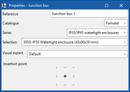
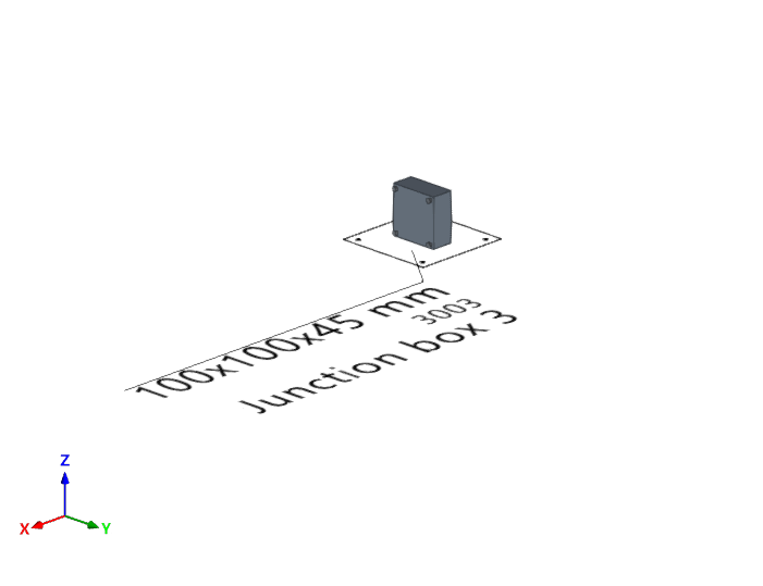
Junction box
Enter a junction box (or branch box) from a manufacturer's catalogue and set your display preferences.
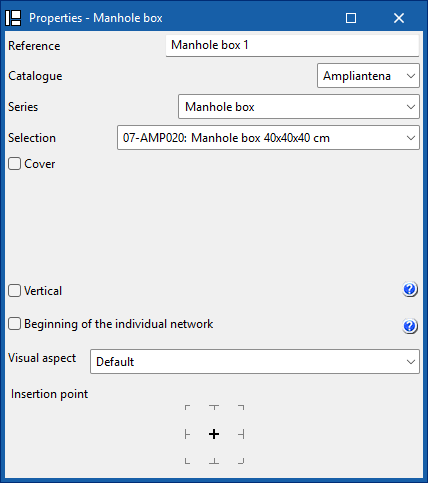
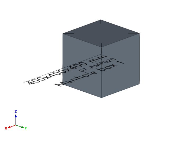
Manhole box
Enter a manhole into the BIM model from a manufacturer's catalogue, add a cover from a catalogue, and configure your display preferences. In addition, if the installation has several independent verticals, you can define the reference of the vertical to which this element belongs.
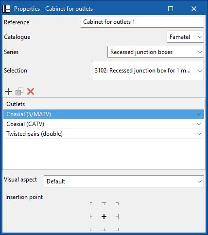
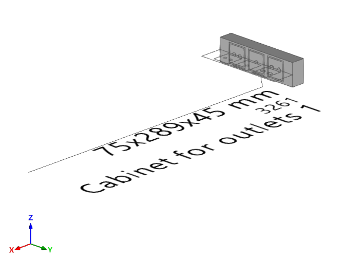
Outlet box
Enter an outlet box into the BIM model from a manufacturer's catalogue. You must indicate the socket bases and whether they are coaxial, coaxial (S/MATV), coaxial (CATV), twisted pair, twisted pair (double), fibre optic or reserve. You can also configure your display preferences.
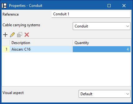
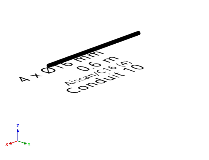
Conduit
Enter the tray, channel, or pipe type ducting from a manufacturer's catalogue, and configure your display preferences.
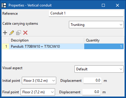
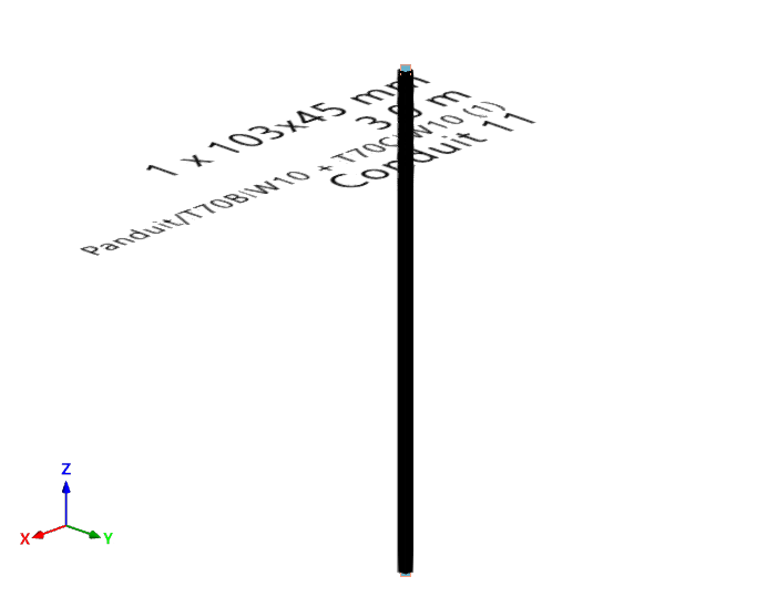
Vertical conduit
Enter tray, channel or pipe type vertical ducting from a manufacturer's catalogue, define its start and end points, and configure your display preferences.
| Note: |
|---|
| When inserting elements, references are generated sequentially, which prevents duplication both during insertion and when duplicating or creating symmetries. In addition, the insertion point functionality is included, which allows you to capture and anchor elements to architectural references for more precise placement in the model. |
| Further information: |
|---|
| The program incorporates an automatic check for repeated ID references, using an error warning, which allows duplications in model elements to be detected. It also identifies disconnected elements of the installation such as manholes, pipes, boxes or sockets, making it easier to detect inconsistencies in the design. |
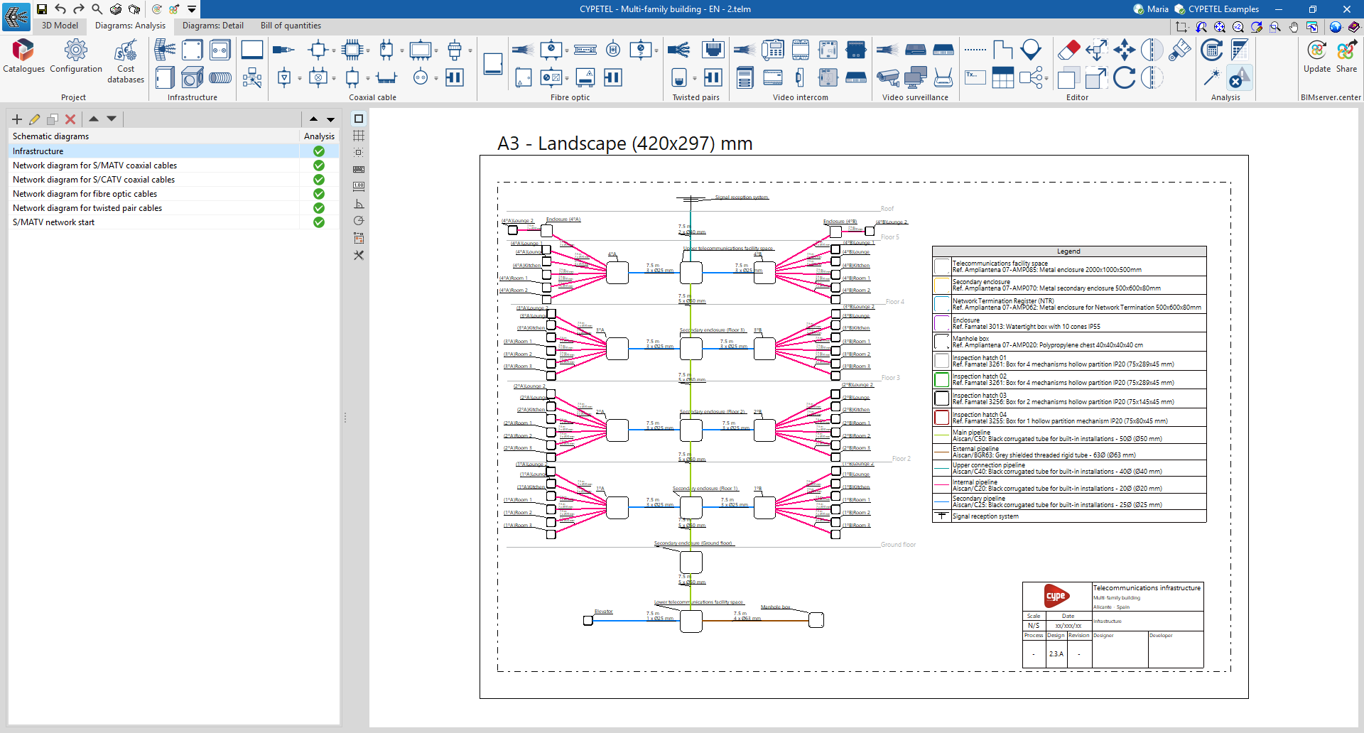
Entering infrastructure elements into the diagram
The "Diagrams: Analysis" tab can manually generate telecommunications infrastructure diagrams based on the information from the model developed in the "3D Model" tab, using the available drawing tools:
- To compose the diagrams from scratch, first create the sheets of the necessary formats using the options on the left side. Then, insert the diagram elements into the work area on the right side using the options in the top toolbar.
Within the "Diagrams: Analysis" tab, in the "Infrastructure" group of the main toolbar, you will find the options that allow you to insert the elements of the telecommunications infrastructure:

- Signal reception system*
- Cabinet / Distribution box*
- Junction box*
- Manhole box*
- Outlet box*
- Conduit
*The data for these infrastructure elements can be linked to the 3D model using the selection list and disappear once they have been entered.
In the case of conduits, the link to the elements of the 3D model is made automatically, as it analyses the connections between elements in the diagram.
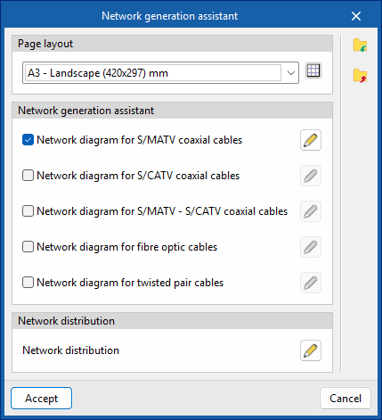
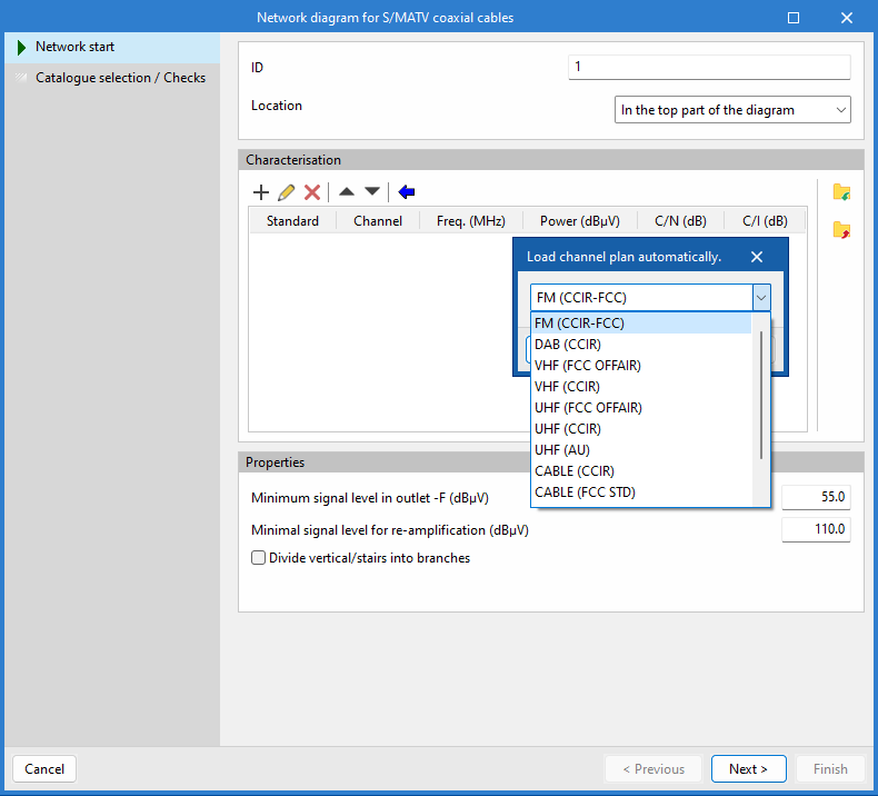
Automatic assistant for generating telecommunications networks

The program features a wizard for rapid diagram creation that optimises the design process by significantly reducing manual modelling time. It also facilitates regulatory compliance and minimises errors, providing an efficient solution for creating telecommunications network diagrams.
| More information: |
|---|
| The settings configured in the wizard are retained in the project when the programme is closed. In addition, they can be imported and exported to files on disk from the options in the right-hand column, allowing them to be reused in other projects. |
Analysing and checking the telecommunications installation
In the "Analysis" group of the main toolbar of the "Schemes: Calculation" tab, you can access the following utilities:

Update results
This option can analyse the installation and check whether the parameters calculated in the telecommunications installation elements are within the permitted ranges, based on the configuration defined in the "Configuration" section of the "Project" group.
The result is a direct display with error or warning messages about the elements that present a problem in the check, as well as a detailed report if the "Consult results" tool is used on each element.
In turn, the "Update results" option can detect incidents related to the consistency between the design made in the "3D Model" tab and the elements entered in the infrastructure network diagram. This function facilitates the detection of duplicates, the updating of conduit lengths and the selection of products, thus ensuring correlation with the 3D model and helping to complete the installation diagram.
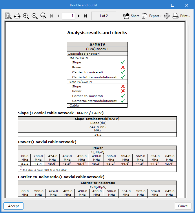
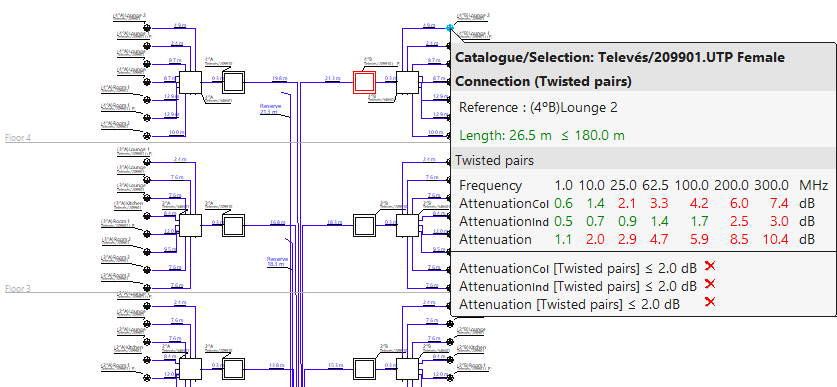
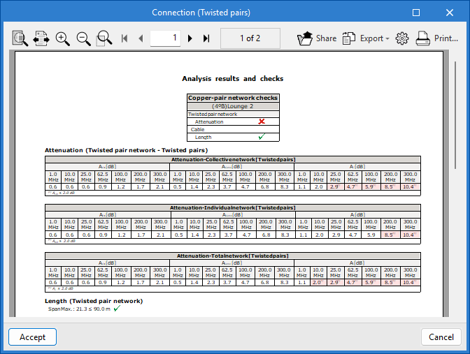
View results
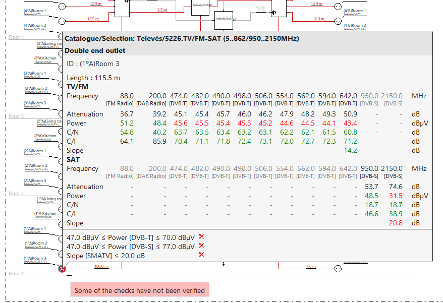
This option allows you to view the checks for elements where the "Check" option has previously been assigned.
After analysing and activating the "View results" tool, from the diagram and by hovering over the element, it is possible to view the checks that have been carried out. Checks that do not comply are highlighted in red, and those that do comply are highlighted in green.
In addition, when you click on the element, a detailed list of the checks performed appears.
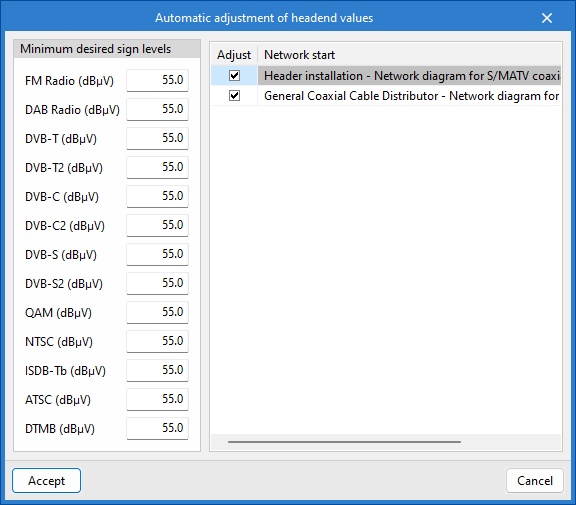
Automatic adjustment of headend values
This tool can modify the signal levels of the channels at the "network start". It also adjusts the gain of the headend amplifiers of the reception and amplification system to meet the requirements of the network start.
Show/hide incidents
Activating this option highlights the elements of the installation that have warnings or errors, either in their introduction, editing or in the analysis checks, such as incidents resulting from incorrect design or possible regulatory non-compliance. When you position the cursor over each incident, a descriptive message is displayed with details of the warning or error.
Results output
The analysis results can be obtained in the following ways:
Reports
The reports generated as a result of the system analysis can be exported to various formats (TXT, DOCX, PDF, etc.) for printing or modification.
CYPETEL exports several types of reports:
- Analysis results
Report and checks performed by analysing the telecommunications installation. - Materials table
Reports with references, description of the elements entered and their measurements.
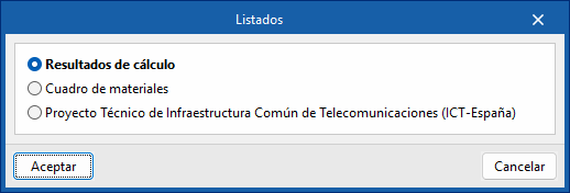
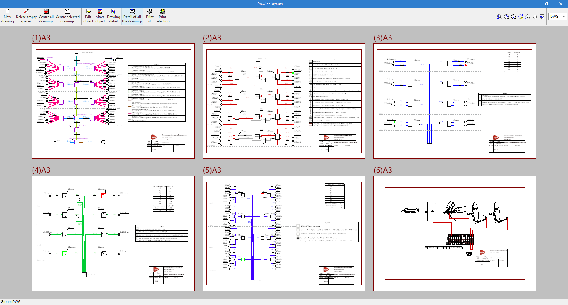
Drawings
CYPETEL can generate plans of the main diagrams, which can be sent to any printing device or exported to different formats such as DWG, DXF or PDF, among others.
Bill of quantities in BC3 and CSV formats
In addition to generating "Bill of quantities reports" from the "Bill of quantities" tab, CYPETEL automatically extracts the measurements of the installation equipment and can export them to the standard FIEBDC-3 (.bc3) format or CSV format, so that they can be read by any compatible application.
To export to BC3, simply use the "Export to BC3 format" tool in the top toolbar of the interface and assign a name to the file.
Similarly, to export to CSV, simply use the "Export to CSV format"’" tool in the top toolbar of the interface, assign a name to the file and tick the desired boxes to include associated information (reference, unit, description, etc.).
IFC and GLTF files compatible with BIMserver.center
When exporting the project to the BIMserver.center platform, an IFC file and a 3D model in GLTF format are automatically exported for the integration of the building model into the Open BIM project, allowing it to be viewed:
- on the online platform;
- in the BIMserver.center application for iOS and Android;
- in virtual reality and augmented reality;
- in other CYPE programs.
Integration into the BIMserver.center platform
Many of CYPE's programs are connected to the BIMserver.center platform and allow collaborative work to be carried out via the exchange of files in formats based on open standards.
Please note that, to work on BIMserver.center, users can register on the platform free of charge and create a profile.
When accessing a program connected to the platform, the program connects to a project in BIMserver.center. This way, the files of the projects that have been developed collaboratively in BIMserver.center are kept up to date.

| More information: |
|---|
| For further details related to using CYPE software via the BIMserver.center platform, please click on this link. |


