Customize Consent Preferences

We use cookies to help you navigate efficiently and perform certain functions. You will find detailed information about all cookies under each consent category below.

The cookies that are categorized as "Necessary" are stored on your browser as they are essential for enabling the basic functionalities of the site.... 

Always Active
Strictly necessary cookies are absolutely essential for the website to function properly. These cookies provide the basic functions and security features of the website, anonymously.
Functionality cookies help to carry out certain functions, such as sharing the website content on social media platforms, collecting feedback, and other third-party features.
Performance cookies are used to understand and analyse the key performance indicators of the website, thus helping to provide a better user experience for visitors.

No cookies to display.

Analytics cookies are used to understand how visitors interact with the website. These cookies help provide information on website metrics, such as the number of visitors, bounce rate, traffic source, etc.
Advertisement cookies are used to provide visitors with relevant ads and marketing campaigns. These cookies track visitors across websites and collect information to provide customized ads.

No cookies to display.

Unclassified cookies are cookies that are being analysed and have not yet been assigned a category.

No cookies to display.

Share

Module code

PLA

Associated programs

Modules required for installation

In CYPECAD

In CYPE 3D

Baseplates

The "Baseplates" module designs, edits and checks welded baseplates for any steel column layout (simple and built-up sections, rolled, reinforced and cold-formed sections). It does not include the analysis and design of welds between plates, stiffeners, columns and bolts except for rolled or welded steel I sections. The Joints I, Joints II, Joints III and Joints IV modules common to CYPE's CYPECAD and CYPE 3D programs carry out the analysis and design of welded or bolted joints in I sections, including their welded anchor plates on footings, pile caps and floor slabs.

The program generates:

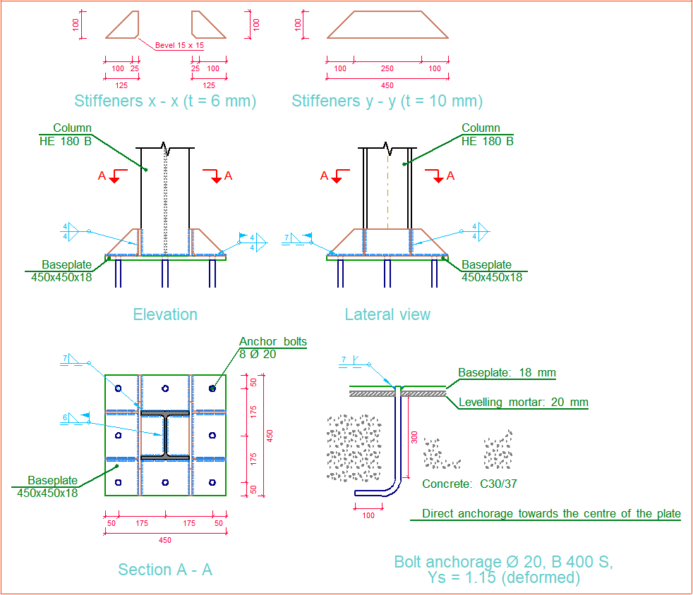
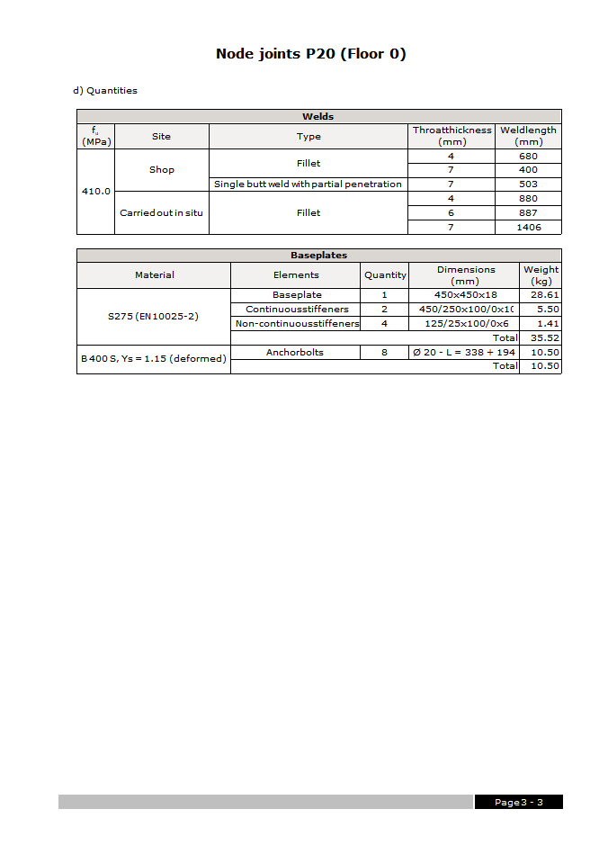
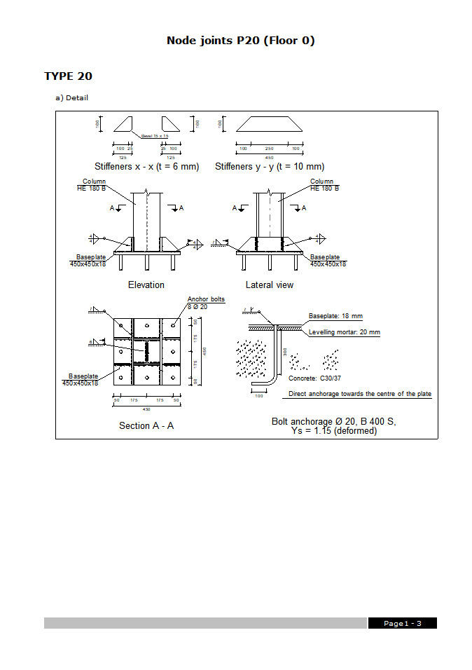
  • The construction details of the joint.
  • The check and quantities reports of the joint.
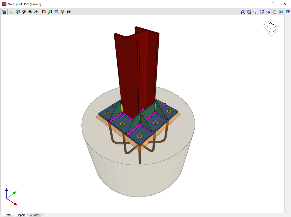
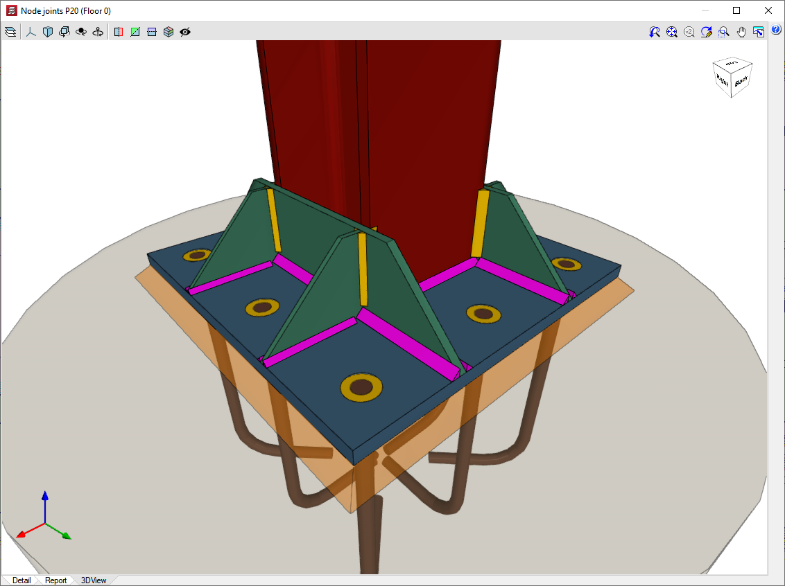
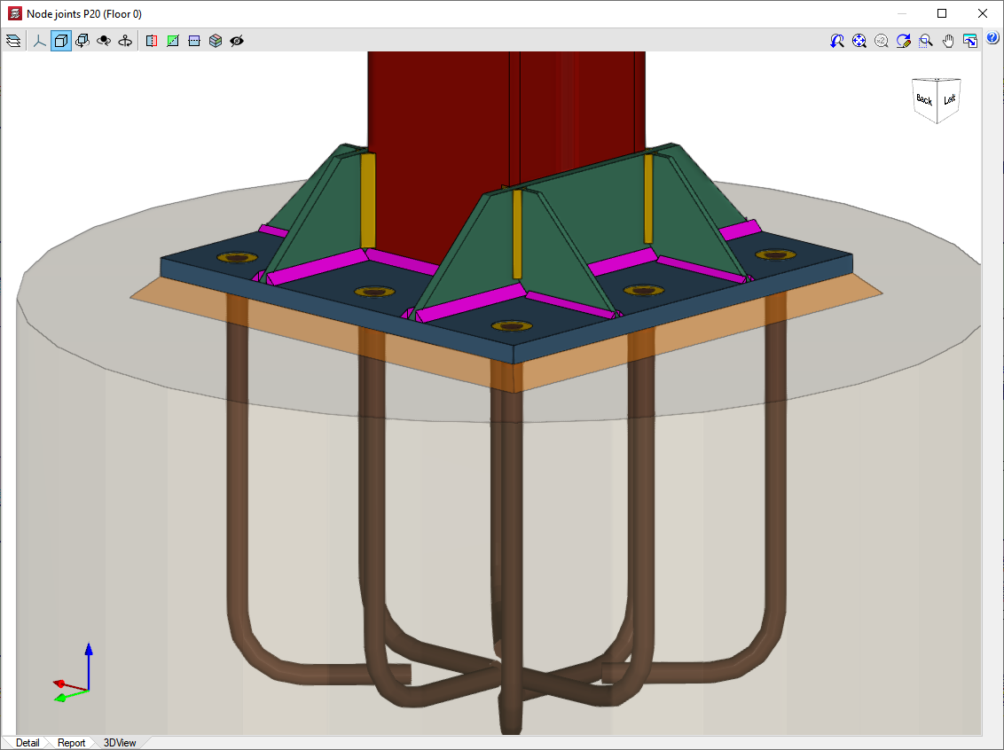
  • The actual 3D view of the joint.

An actual 3D view of each joint designed by the program can be displayed in perspective or isometric projections. The elements that make up the joint (columns, beams, stiffeners, welds) are drawn in different colours. The welds are represented in two colours in order to distinguish between those made in the workshop and those made at the assembly site. Furthermore, the user can freely rotate and expand the 3D view. These features make it much easier to understand the assembly of the joint.