Viewing and modifying rotational stiffness values
The rotational stiffness values at the ends of the bars in the model's joints can be reviewed and assigned using the "Rotational stiffnesses" option, available in the top toolbar of the "Joints" tab (under the "Structure" tab).

Accessing the "Options" window
Rotational stiffness values can only be viewed and modified if joints have been used in the structure for which it is necessary to define their rotational stiffness, due to the presence of deformable components, as is the case with bolted joints.
If this is not the case, the program will display a message when you click on the option stating that "No connections have been applied which require their rotational stiffness to be defined".
Alternatively, if the joints have not been designed, the program will display the message "The rotational stiffness of the connections is going to be calculated", asking whether you wish to continue.
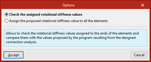
After selecting "Yes", the "Options" window opens, displaying the following two options.
Individual review of the assigned rotational stiffness values
The first option in the "Options" window, "Check the assigned rotational stiffness values", allows you to check the rotational stiffness values assigned to the ends of the bars in each joint group and compare them with the values suggested by the program following the analysis of the designed joints.
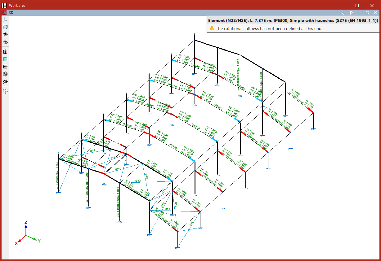
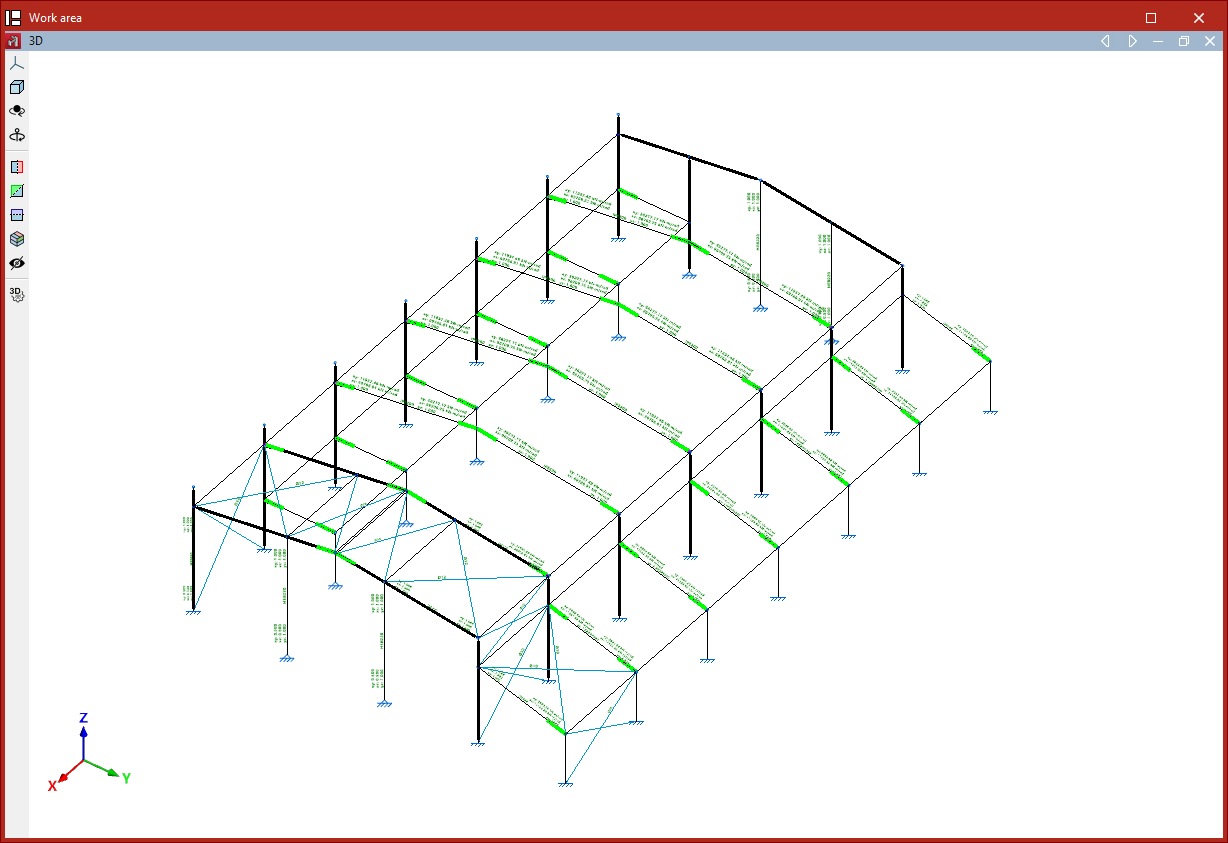
When you select this option and click "Accept", the ends of bars whose assigned stiffness differs significantly from that resulting from the joint analysis are highlighted in red.
When the cursor is positioned over the end of a bar with an analysed connection, the program displays a tooltip containing the messages associated with that end and highlights all the ends of bars that form part of the same type of connection and have been assigned the same rotational stiffness.
The message "The rotational stiffness has not been defined at this end" will be displayed if this has not yet been done.
Clicking the left mouse button on the desired end of the part opens the "Rotational stiffnesses" window.
"Rotational stiffness" window
The information displayed, and the options available in the "Rotational stiffness" window, are explained in detail below:
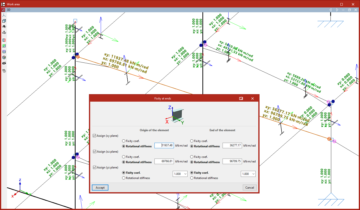
Assigning rotational stiffnesses and/or fixed-end coefficients in the xz and xy planes
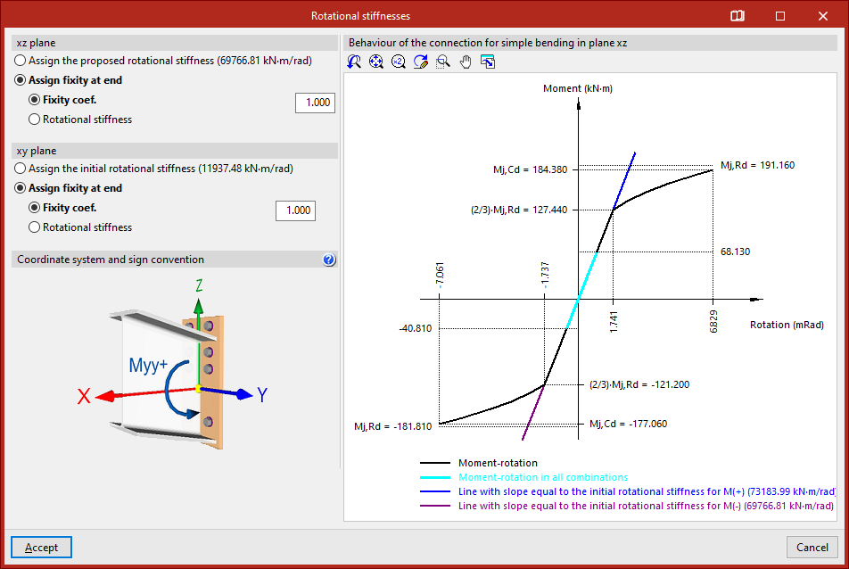
The top-left corner displays information about the type of fixed support assigned to the end of the bar and the rotational stiffness value proposed by the program.
The program allows you to retain the original values or change them, both in the "xz plane" and the "xy plane". If you change the value, the change applies to all selected parts.
By default, the program leaves "Assign fixity at end" selected, with a "Fixity coefficient" value set to one.
You can enter a different coefficient or tick the "Rotational stiffness" box to enter its value directly in the units displayed by the program.
You can also "Assign the proposed rotational stiffness" and "Assign the initial rotational stiffness" calculated by the program in each of the planes based on the joint characteristics.
Coordinate system and sign convention
The bottom left-hand corner shows the "Coordinate system and sign convention" used in the analysis of the joints.
This system is defined by the X, Y and Z axes, with their origin at the centre of gravity of the cross-section of the section to be joined. The Y and Z axes lie within the plane in which the joint is made, and the positive direction of the X axis is directed towards the side from which the element to be joined is inserted. The X axis may not be parallel to the section axis if the element does not form a right angle with the plane of the joint.
The sign convention for positive values around the Y-axis is also shown.
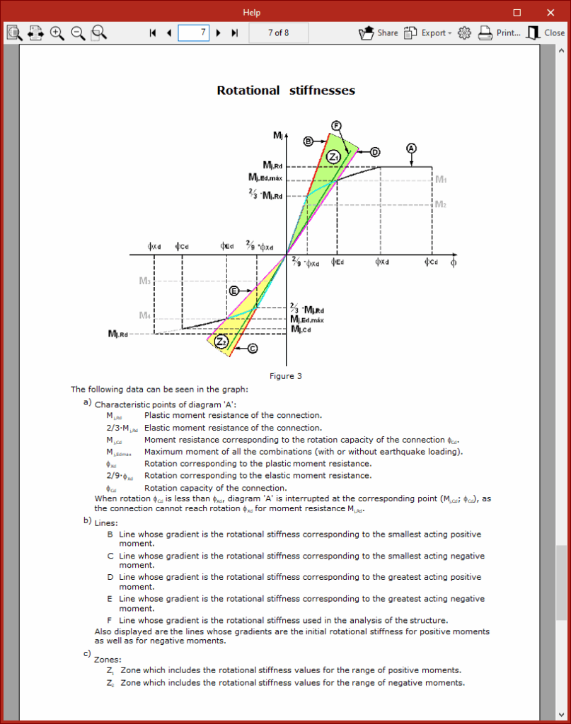
Moment-rotation curve
On the right is a graph showing the "Behaviour of the connection for simple bending in plane xz", expressed by the moment-rotation curve.
In the title bar of the "Rotational stiffnesses" window, you can click the relevant button to open a "Help" window containing information on the construction and display of the characteristic moment-rotation diagram, which is unique to each joint.
After clicking "Accept" in the "Rotational stiffness" window, the program may display the message: "Due to the changes that have been carried out on the end fixities of the elements, the job will have to be re-analysed once the editing has concluded."
At this point, click "Accept" again. The program will highlight the ends of the bars whose rotational stiffnesses match those suggested by the program in green.
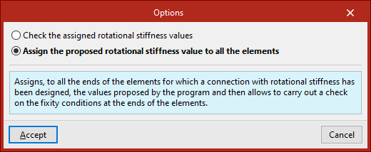
Automatically assigning the proposed rotational stiffness values to all parts
Rotational stiffness values can be assigned to all bars in the structure automatically. To do this, in the "Options" window that appears when you click on the "Rotational stiffnesses" option, you must tick the second option, "Assign the proposed rotational stiffness value to all the elements".
Therefore, the program assigns the values it proposes to all the ends of the bars for which a rotationally rigid connection has been analysed.
After clicking “Accept”, left-clicking on the ends of the component allows you to check the support conditions and rotational stiffness in the same way as described above.
Similarly, the ends of the component whose rotational stiffnesses match those proposed by the program3 are shown in green.
General considerations
We recommend analysing the structure again after reviewing the rotational stiffnesses, as any changes to these may affect the structure’s behaviour, particularly the rotation between components at a joint. This can be done via the “Analysis” tab by selecting the “Analyse” option in the “Stress / Strain” section.
Once the analysis has been carried out, the program may report that "There are elements which have been assigned an inadequate rotational stiffness value". In this case, it may be advisable to repeat the process of checking the rotational stiffness values until sufficiently accurate values are assigned, so that no warning messages appear in subsequent analyses.
Finally, it is worth noting that from the "Properties" tab, by using the "Embedding" option in the "Beams" section, after selecting the bars with the left mouse button and confirming with the right mouse button, you can view the rotational stiffness value applied to the ends of the bars following the previous operations.
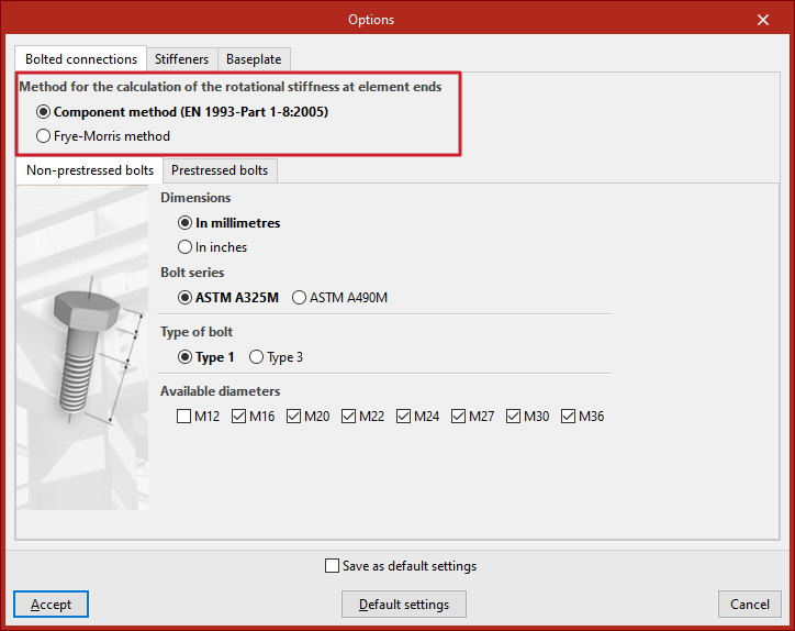
Selecting the calculation method for the rotational stiffness
On the “Project” tab, under “General data”, by clicking on “Connections” and then on “Options”, the program allows you to choose the “Method for the calculation of the rotational stiffness at element ends” from either the “Component method” or the “Frye-Morris method”.
This option is only available for certain codes.