

Generating loads and loadcases for connections from the BIM model
You can generate loads and loadcases automatically from the BIM model in CYPE Connect.
To do this, use the "Generate from the BIM model" option on the top toolbar of the "Analysis" tab within the connection editor. This option is available when the project has been created from a BIM model with internal forces (such as those from CYPECAD or CYPE 3D).

Generate from the BIM model
Clicking on the “Generate from the BIM model” option opens the “Read the loadcases from BIM model” window, which contains three sections: “Stress/Strain”, “Capacity design” and “Rotational stiffness”.
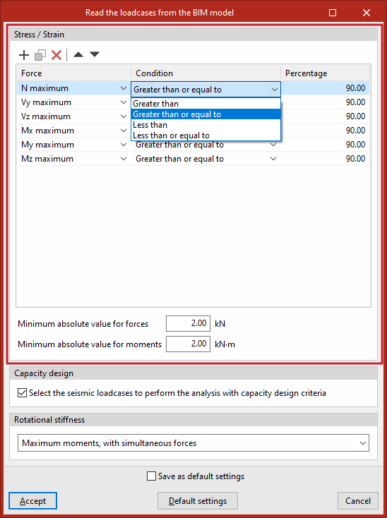
Stress / Strain
In the "Stress/Strain" section, the program can filter the load combinations to be imported from the BIM model for this calculation. Not all load combinations have significant values; therefore, it may be advisable to filter the number of combinations to be imported in order to reduce the calculation time.
To do this, filters are entered one by one into a table with the columns "Force", "Condition" and "Percentage".
By default, a filter is provided for each of the six types of "Force": axial (“N maximum”), shear forces in the Y and Z directions (“Vy maximum”, “Vz maximum”), and moments in the X, Y and Z directions (“Mx maximum”, “My maximum”, “Mz maximum”).
For each type of force, the combinations in which that particular force satisfies the selected "Condition" ("Greater than", "Greater than or equal to", "Less than" or "Less than or equal to") in relation to the specified "Percentage" of the maximum value, for both positive and negative values.
For example, you can specify the condition that the force must be "Greater than or equal to" 90 per cent of the maximum stress. This prevents loadcases with low force values from being imported.
In addition to filtering by percentage of effort, you can set a minimum value to determine whether or not to include the combinations by entering an "Absolute minimum value for forces" and an "Absolute minimum value for moments" in the boxes at the bottom of this section.
Design by capacity
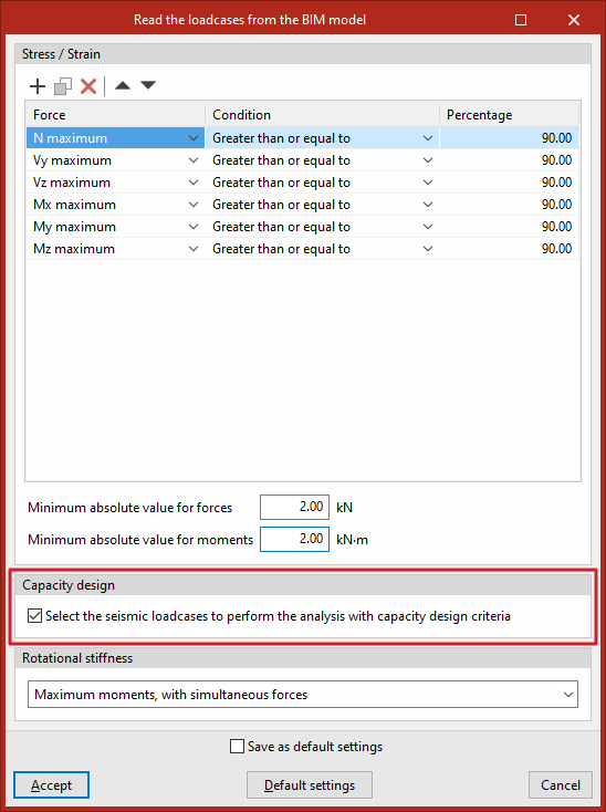
In the "Capacity design" section, you can tick the relevant box to "Select the seismic loadcases to perform the analysis with capacity design criteria".
The program will therefore identify loadcases of this type and automatically tick the "Capacity design" box for them in the list of loadcases.
Rotational stiffness
The "Generate from BIM model" option can also be used to import loads for rotational stiffness analysis. In addition to the loads, the elastic lengths of the bars in the structural model are also imported; these lengths are required for the correct classification of the connection.
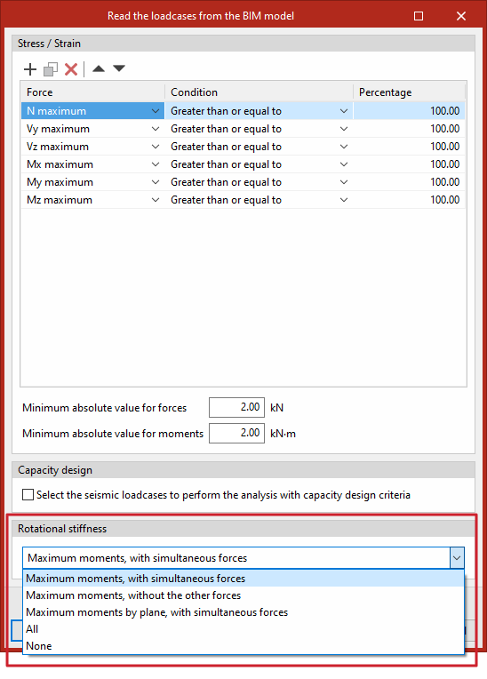
From the drop-down menu in the "Rotational stiffness" section, select one of the following five options to import the loadcases based on the internal forces:
- Maximum moments, with simultaneous forces
Enter the loadcases with the highest moments "My" or "Mz", with a positive or negative sign, as well as the other associated stresses. - Maximum moments, without the other forces
For loadcases involving peak moments, only the values of "My" and "Mz" are relevant. - Maximum moments per plane, with their corresponding
forces
Import the loadcases corresponding to the maximum bending moments, together with their associated force components, by plane (i.e. the XY and XZ planes). - All
Import all loadcases. - None
Does not import any loadcases.
After clicking "Accept", the "Loadcases" and "Loads" for the sections involved in the connection are generated based on the defined configuration.
From here, you can click on the relevant buttons on the top toolbar to view the information generated in both sections or to make changes if required.
