Entering loads in the connection editor
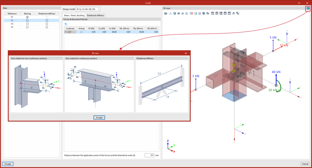
To enter loads on the bars in the program, click on the "Loads" option in the top toolbar of the "Analysis" tab within the connection editor.

Loads
The "Loads" option is used to define the loads applied to the bars in the connection for each loadcase.
The loads may have been generated automatically using the "Generate from BIM model" option.
You can edit them or enter them manually. In that case, select each of the "Bars" in the table on the left, which shows their "Reference", as well as the "Load-bearing" and/or "Rotational stiffness" columns, where applicable.
Selecting load-bearing beams
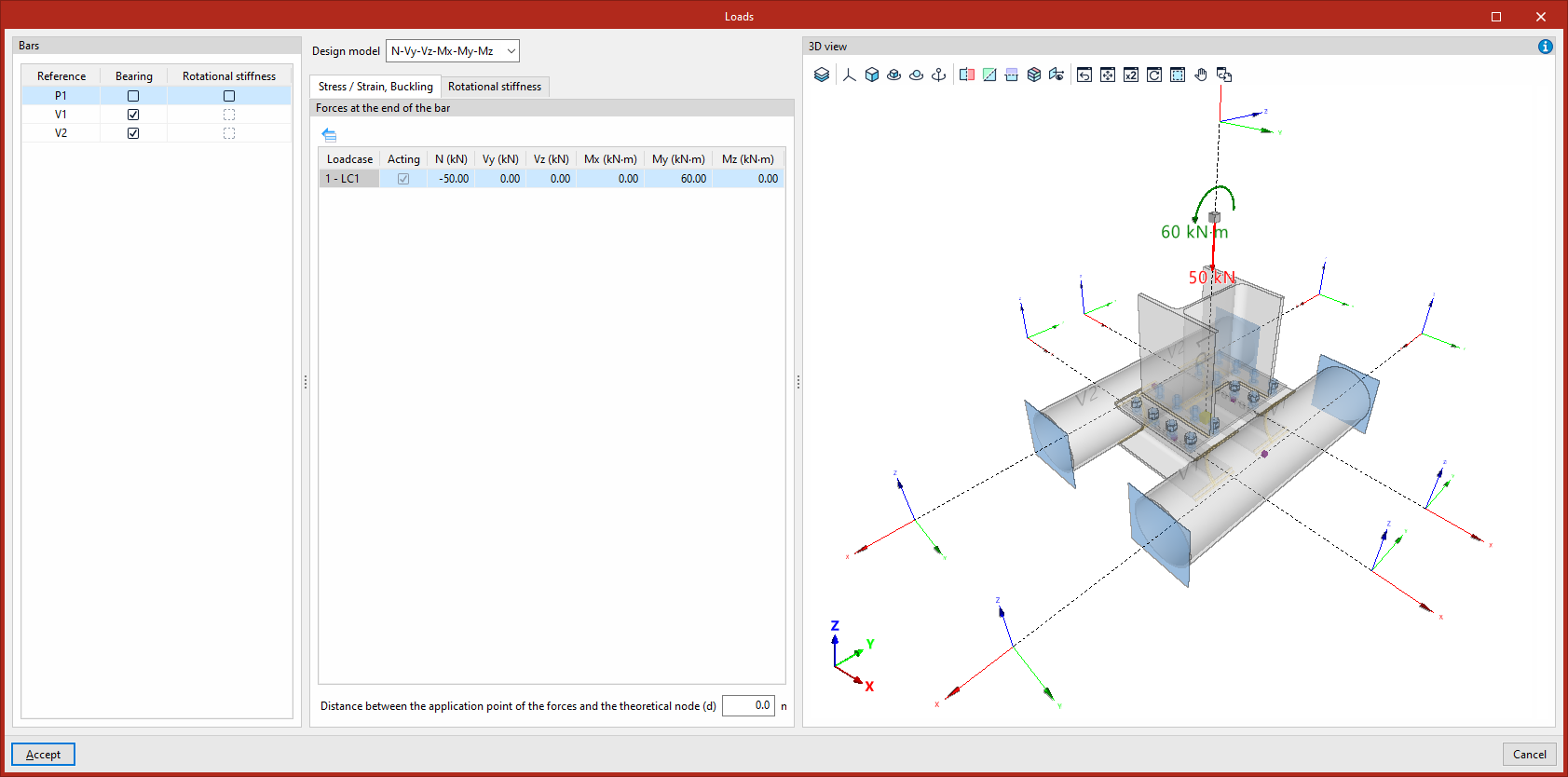
In the connection analysis model, you must define one or more bars of the connection as "Load-bearing" by ticking the corresponding box in the column of the same name, unless an baseplate has been defined (in these connections, no bars may be designated as load-bearing, and this column will not be displayed).
The remaining bars are connected to this component, to which the loads are applied.
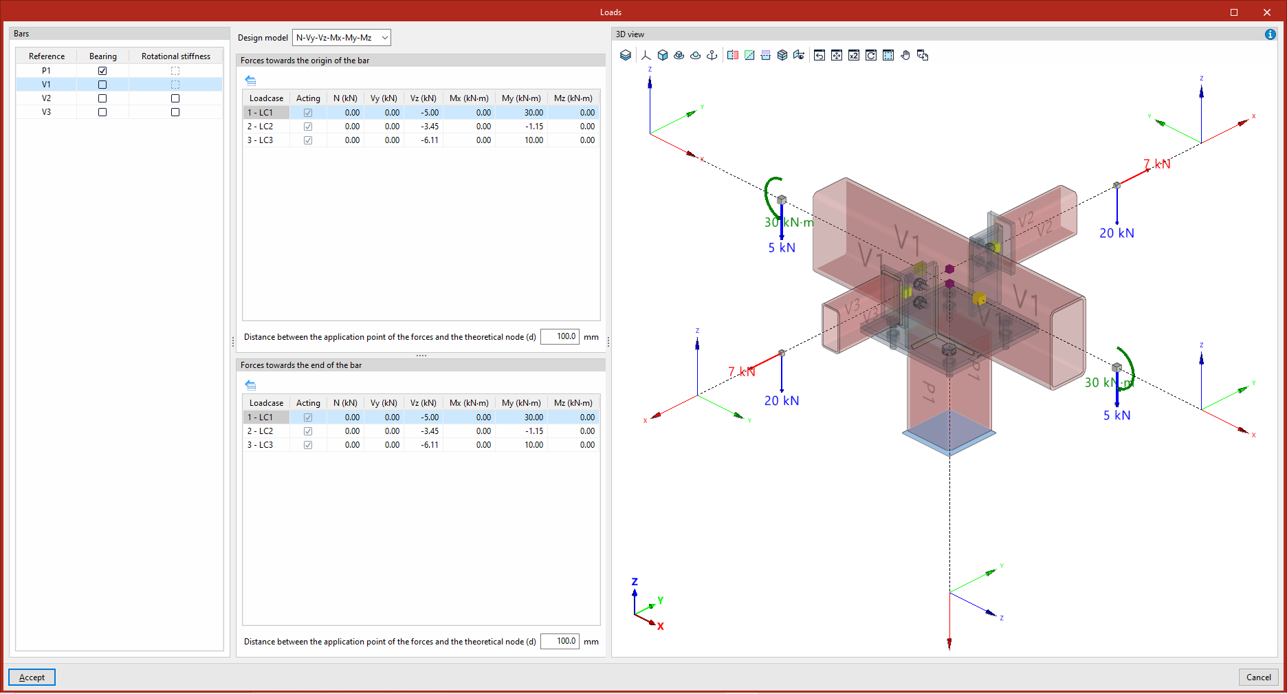
Each load-bearing beam has an external connection at one end. If the load-bearing bar is continuous or runs through the connection, you must specify whether there is an "External connection" "At both ends", "At the start end" or "At the final end" of the section by selecting one of the options from the drop-down menu that will appear in the centre of the dialog box.
The program displays a message stating that "The forces do not need to be entered into the load-bearing section, as they are determined by equilibrium".
Selecting the design model
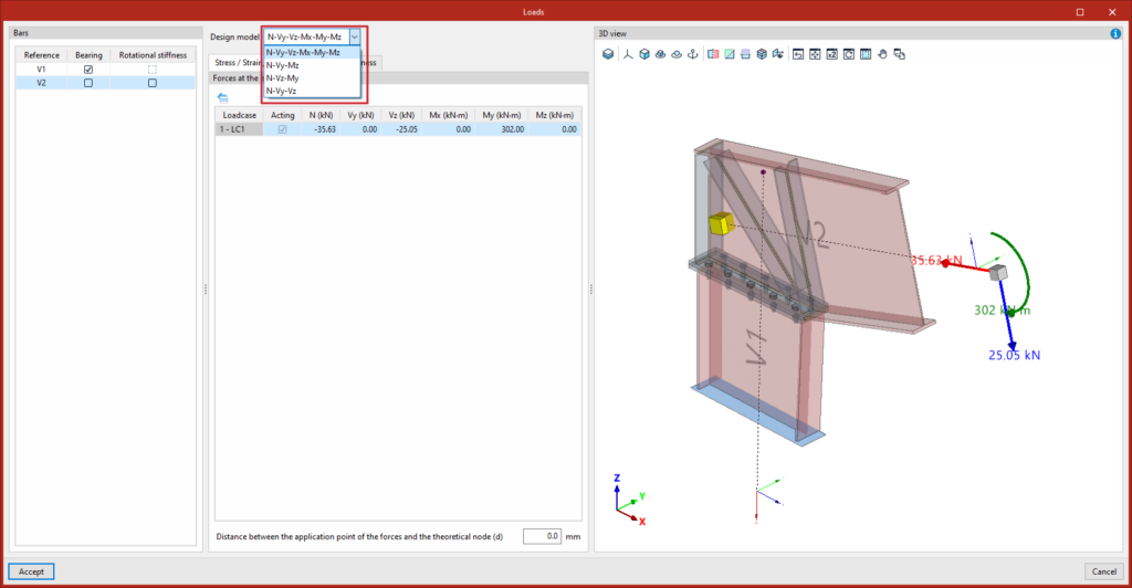
Each non-load-bearing bar includes the "Design model" drop-down menu, which allows you to select different load and constraint configurations, better suited to various structural situations. You must select one of the following options:
- N – Vy – Vz – Mx – My – Mz
This is the default model. The end of the beam has no external connections, allowing the six internal forces to be defined: the axial force, the shear forces in the Y and Z directions, and the moments in the X, Y and Z directions. - N - Vy - Mz
This model allows loads to be defined in the XY plane. The end of the beam is constrained against displacement along the z-axis and rotation about the y-axis. The axial force, the shear force in the Y-direction and the moment in the Z-direction are defined. - N - Vz - My
This model allows loads to be defined in the XZ plane. The end of the beam is constrained against displacement along the y-axis and rotation about the z-axis. The axial force, the shear force in the Z-direction and the moment in the Y-direction are defined. - N - Vy - Vz
In this model, the end of the bar has its rotational degrees of freedom restrained, while no moments can be applied. The axial force and the shear forces in the Y and Z directions are defined.
In the central part of the dialog box, below this drop-down menu, there are two tabs for defining the load or force tables in the units specified for each "Loadcase" (indicating whether it is "Acting" or not). Right-clicking on the cells brings up additional tools that allow you to copy and paste data directly from spreadsheets.
In the design model, the program will apply loads at the end of each section to calculate the forces entered by the user at the specified point.
"Stress/Strain, Buckling" tab
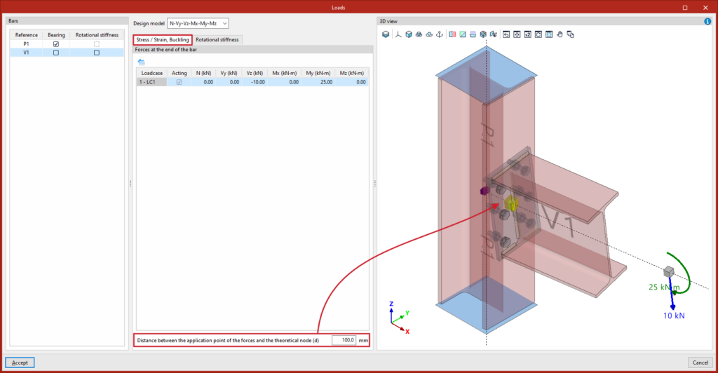
In the "Stress/Strain, Buckling" tab, the loads or "Forces at the end of the bar" are defined for each load case to carry out these analyses (and the "Forces towards the origin of the bar" if the bar is continuous or passes through the connection), by entering their values in the cells of the central table.
In the field below each internal force table, you can also enter the “Distance between the point of application of the forces and the theoretical node”. This allows you to specify where the forces are being defined on each bar:
- If the forces at the theoretical node – that is, the point where the section axes intersect – are being entered, the distance value must be zero.
- If you wish to input forces from another point – for example, those acting on the face of a column – you must enter a distance value equal to half the width of that column.
This distance will also be read from the BIM model, provided that the structure has been analysed considering the finite dimensions of the connections.
'Rotational Stiffness' tab
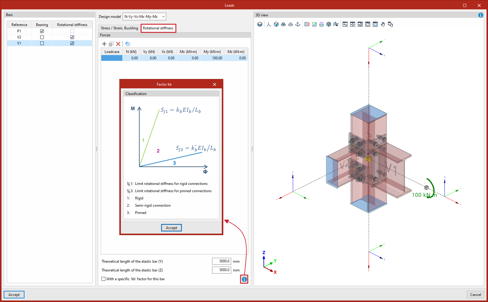
In the "Bars" browser on the left, you can also select the bars for which you wish to calculate the rotational stiffness of the connection by ticking the "Rotational stiffness" box in the relevant column.
The "Rotational stiffness" tab requires a list of loads or "Forces" for each loadcase, which can be entered into the cells in the central table.
In addition, at the bottom, you must enter the lengths of the elastic bar in the structural model (used to determine the limit stiffnesses of rigid or hinged connections) and the kb factor:
- Theoretical length of the elastic rod (Y)
- Theoretical length of the elastic rod (Z)
- With a "kb" factor specific to this bar (optional)
The diagram, which can be accessed via the help button at the bottom, shows how the connection is ‘classified’ as "Rigid" (1), "Semi-rigid" (2) or "Hinged" (3) in the M-Φ plane, based on the definition of the "Limit rotational stiffness for rigid connections", Sj1=kbEIb/Lb, and the "Limit rotational stiffness for pinned connections", Sj3=k'bEIb/Lb.
"Buckling" tab
This tab appears only if the “Perform the instability analysis with the same loads as the Stress/Strain analysis” option has been deselected in the “Analysis options” and allows you to enter the internal forces specifically for the buckling analysis.
Editing forces
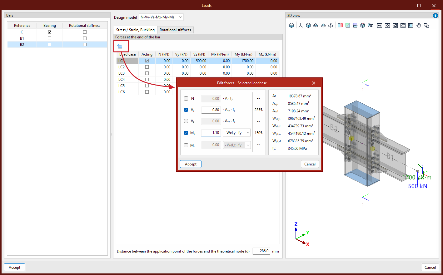
The "Edit forces – Selected loadcase" tool, which is common to both tabs, allows you to define the forces applied to each bar based on its mechanical properties:
- The "N" axis is defined by entering a coefficient that multiplies the product A·fy.
- The "Vy" cutting factor is defined by entering a coefficient that multiplies the product Avy·fy.
- The "Vz" shear force is defined by entering a coefficient that multiplies the product Avz·fy.
- The "My" moment is defined by entering a coefficient that multiplies the product Wel,y·fy, or alternatively Wpl,y·fy.
- The "Mz" moment is defined by entering a coefficient that multiplies the product Wel,z·fy, or alternatively Wpl,z·fy.
- On the right, the values of the mechanical properties A, Avy, Avz, Wel,y, Wpl,y, Wel,z, Wpl,z and fy for the bar are shown.
For example, this feature makes it easier to design connections with a higher strength than that of the joined bars – a common requirement in various seismic design codes.
3D view
In the "3D view" on the right-hand side of the dialog box, the loads applied to each bar in the connection are displayed graphically according to the selected loadcase.
The theoretical node and the point at which the forces are applied are also shown as a yellow cube, cylinder or sphere (depending on the calculation model chosen).
In addition, the help button in the top right-hand corner opens a diagram showing the “Axis criteria for continuous sections” and the “Axis criteria for non-continuous sections” (which allows you to determine the direction and sense of the forces applied with a positive sign), as well as the parameters relating to the ‘Rotational stiffness’ analysis (Ly and Lz).
To apply the changes, click “Accept”.