

Selection and editing micropiles
Micropiles can be selected and edited when adding a new "Pile cap" foundation element or when editing an existing pile cap containing micropiles, using the "Piles" option in the edit window.
General definition
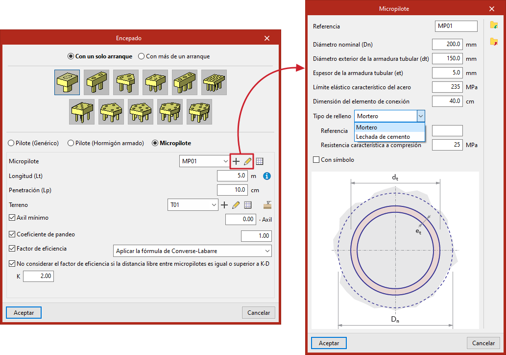
When you select "Micropiles" in the window for entering or editing pile caps, you can specify the properties of each micropile, as well as the ground data and other design parameters.
This option allows for the design and verification of micropiles, as well as the design of the pile cap.
- From the "Micropile" drop-down menu, you can create and select types of micropiles, specifying their geometry, tubular reinforcement, materials and connection plate.
- "Length (Lt)" refers to the length of the micropile beneath the pile cap.
- In "Penetration (Lp)", enter the length of the micropile that penetrates the pile cap. We recommend entering a value between 10 and 15 centimetres.
- Next, you need to configure the "Soil"; you can create, edit and save it to a list of soils using the tools on the right.
- The "Ground elevations" option allows you to define the "Surface elevation of the natural ground", the "Excavation depth" based on the former, and the "Water table".
- By ticking the relevant boxes, you can specify the "Minimum axial force" (based on a coefficient that multiplies the "Axial force") and the "Buckling coefficient".
- Finally, by ticking the "Efficiency factor" box, this can be defined in two ways:
- "Apply the Converse-Labarre formula", for which the following option is available: "Do not consider the efficiency factor if the clear distance between piles is equal to or greater than K·D" (by entering the value "K");
- Or by entering a "User" efficiency factor, which should be entered in the relevant field.
- For pile cap configurations where this is required, the spacing between pile centres is also specified. Furthermore, where rectangular or linear pile groups have been selected, the number of piles is indicated for both the X and Y axes.
- The "Pile displacement" option appears in some types of pile foundations and allows you to apply an “X displacement” and a “Y displacement” to each pile, to make minor adjustments to their position.
Selecting the micropile
In the "Micropile" drop-down menu, when you click on "New" or "Edit selected type", the following is defined:
- The pile's "Reference".
- The "Nominal diameter (Dn)".
- The "Outer diameter of the tubular reinforcement (dt)".
- The "Thickness of the tubular reinforcement (et)".
- The "Characteristic yield strength of steel".
- The "Connection element dimension" (interpreted here as a circular plate; this will determine the size of the connecting rod).
- Selecting the "Filling type" (mortar or cement grout) and specifying the following parameters:
- The "Reference" for the filling.
- Its "characteristic compressive strength".
- The symbol used for the pile (by ticking the "With symbol" box).
The information entered for each type of micropile can be viewed in a list of types and copied, edited or exported to .bibgen files on disk using the relevant options, so that it can be used in other models.