
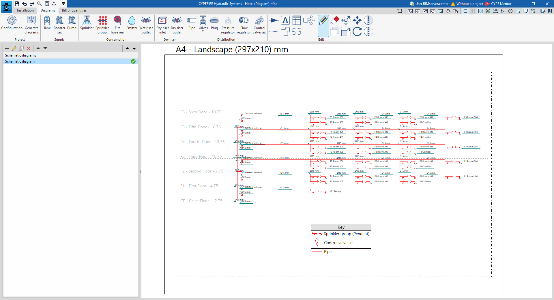
Production and layout of fire-extinguishing hydraulic system diagrams
The "Diagrams" tab, located at the top of the program interface, allows you to automatically generate diagrams of the fire-extinguishing water supply system based on the information from the model created in the "Installation" tab, or to create them manually using the available drawing tools:
- To create diagrams from scratch, you first create the sheets in the required formats using the options on the left-hand side. You then add the diagram elements to the workspace on the right-hand side using the options on the top toolbar.
- To generate diagrams automatically, use the "Generate diagrams" option at the top. The user is then free to modify the generated diagrams on the workspace using the options on the top toolbar.
You can select the composite diagrams on this tab to print them alongside the rest of the site plans using the relevant options.
Schematic diagrams
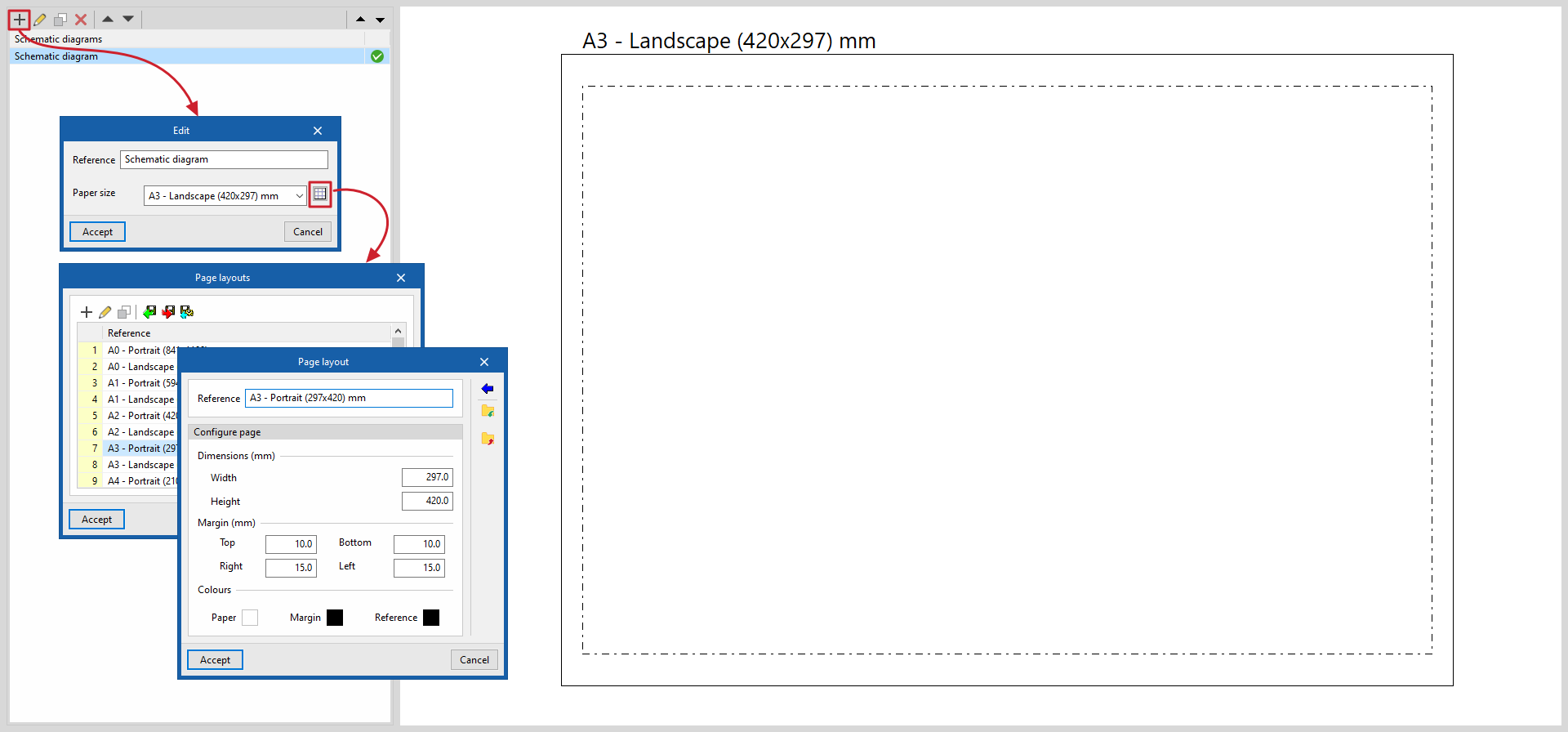
The diagrams of the hydraulic fire-extinguishing system are drawn on sheets of various formats. The tools for creating and managing "Schematic diagrams" are located on the left-hand side of the interface.
When creating or editing a policy template, you can configure the following features:
- Reference
Reference to the schematic diagram. - Paper size
Select the paper size on which the schematic diagram is to be displayed. The available paper sizes can be configured using the "Page sizes" button on the right, specifying their "Reference", dimensions, margins and colours.
Options in the "Project" section
In the "Project" section of the top toolbar, the program offers the following tools:
Settings
Here, you can configure the available table types, view the element groups and display the elements of the fire extinguishing system diagrams. The configuration can be imported or exported to .bib877 files on disk using the options on the right.
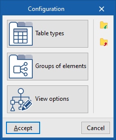
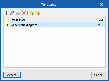
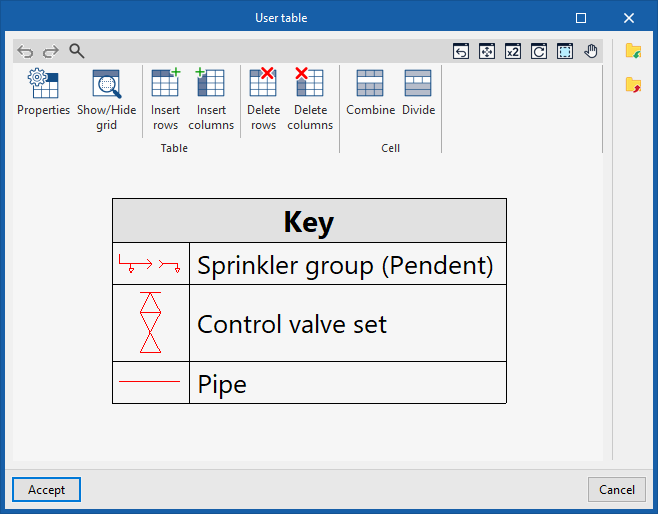
Table types
Allows you to define and edit table types.
When creating a table type, it can be "Generic", specifying the number of rows and columns and filling in the cell contents in a free-form editor, or of the "Legend" type, in which case it is possible to "Automatically generate" it based on the elements laid out in the diagram.
The table types defined here can be used later when inserting tables into the schema via the "Table" option on the top toolbar.
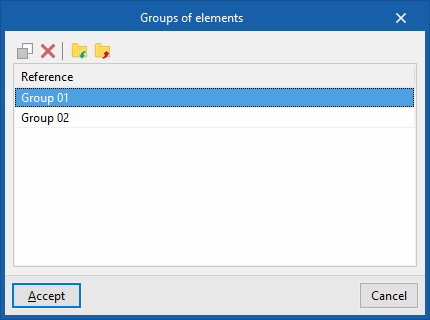
Groups of elements
This allows you to copy, delete, import or export groups of elements previously created using the specific option in the "Edit" group to .bibgen files on your hard drive.
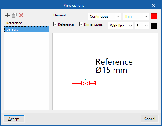
View options
These options allow you to adjust the display of the elements in the fire extinguishing system diagram.
You can create and manage different types of views in the list on the left by entering their "Reference".
Next, for each type of display, the line type used to represent each "Element" is specified, whether "Solid" (with a thickness of "Fine", "Normal", "Thick" or "Very thick") or "Dotted", as well as its colour.
You can add text to the element label, including its "Reference" and "Dimensions", by ticking the relevant boxes. You can also choose whether the label is displayed as "With line", "With box" or "Raised", and select the font size.
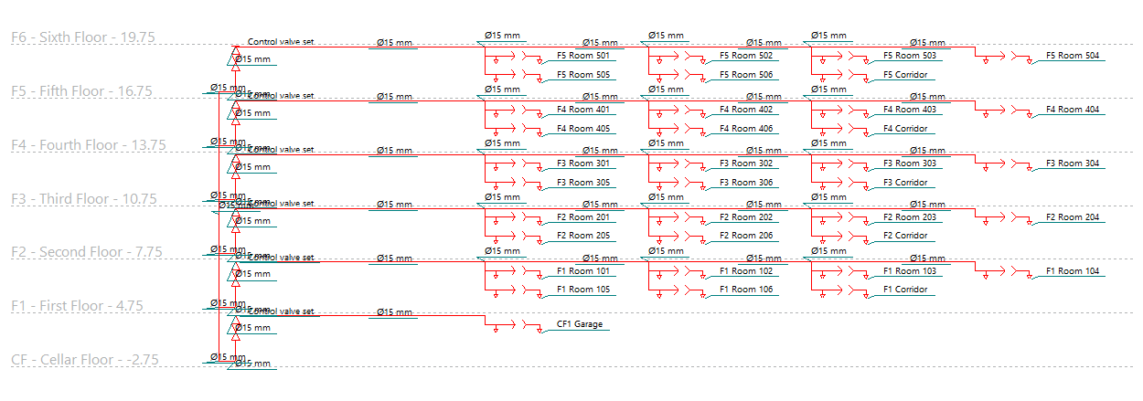
Generate diagrams
This option automatically generates the fire extinguishing system layout based on the information extracted from the model created in the "Installation" tab.
The diagrams generated can be edited later using the tools available at the top.
Tools for adding diagram elements
The following options allow you to freely enter the components of the fire extinguishing system diagram, defining the following parameters for each one:
"Supply" section
- Tank
- Reference
- Appearance
- Booster set
- Reference
- Appearance
- Pump
- Reference
- Appearance
"Consumption" section
- Sprinkler
- Reference
- Installation orientation (Vertical / Suspended / Horizontal / Concealed)
- Appearance
- Sprinkler group
- Reference
- Installation orientation (Vertical / Suspended / Horizontal / Concealed)
- Sprinkler protection above the false ceiling (optional)
- Appearance
- Fire hose reel
- Reference
- Appearance
- Emitter
- Reference
- Appearance
- Wet riser outlet
- Reference
- Appearance
"Dry riser" section
- Dry riser inlet
- Reference
- Number of tickets
- Appearance
- Dry riser outlet
- Reference
- Appearance
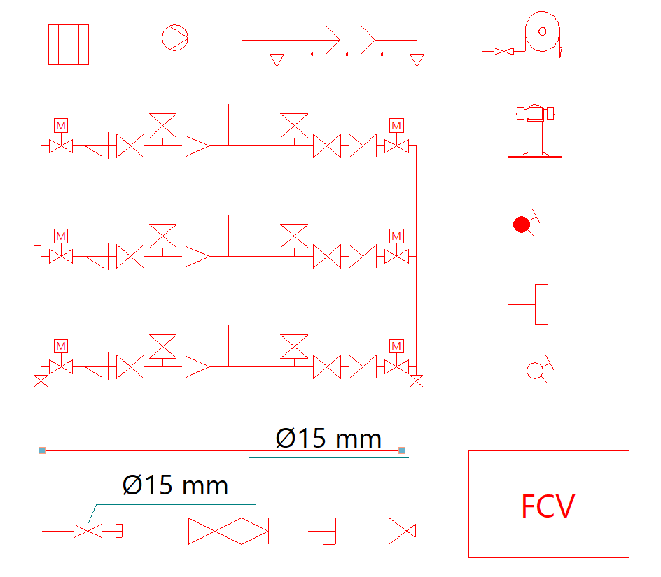
"Distribution" section
- Pipe
- Reference
- Nominal diameter
- Appearance
- Valves (Drain valve, Relief valve, Motorised valve, Gate valve, Control valve, Strainer valve, Flexible connection, Pressure gauge, Flow switch, Flow meter)
- Reference
- Nominal diameter
- Appearance
- Plug
- Reference
- Appearance
- Pressure regulator
- Reference
- Appearance
- Flow regulator
- Reference
- Appearance
- Control valve set
- Reference
- Appearance
Options in the "Edit" panel
The following options allow you to complete the system diagram:
| Flow direction | Add a symbol to a section of pipe to indicate the direction of flow. | |
| Grid line | Enter a reference line. These lines can be used to indicate the layout of the elements in the floor plan across the different floors of the building. | |
| Text | Enter a text, specifying the font, paragraph properties and style. | |
| Polyline | Draw a polyline using points, specifying its type, line weight and colour. | |
| Table | Insert tables containing additional information. The option on the right allows you to create and edit the available "Table types". | |
| Add a continuation point | Insert a symbol at a specific point to indicate that a diagram continues in another section or location. Specify the "Reference" and select the "Visual style". | |
| Groups of elements | Open a menu where you can "Create" groups of elements after selecting them, saving them to a group library, and "Insert" previously created groups of elements. |
The following tools allow you to edit elements of the installation diagram:
| Edit | Edit the parametric properties of the selected element in the model. | |
| Delete | Delete a previously entered item. | |
| Copy | Create a copy of one or more items. | |
| Geometric transformations | Apply a series of geometric transformations to the selected elements, such as changing the position of the endpoints, or moving the elements as a whole by selecting their centre points. | |
| Increase/decrease the size of a group | Apply a "Percentage" to scale the size of the elements. If the "Scale factor" option is enabled, the program will adjust the positions of the selected elements relative to the centre of the group. If the option is disabled, the elements will be scaled up or down without their positions being adjusted. | |
| Move a group | Moves a group of elements. | |
| Rotate a group | Rotate a group of elements. | |
| Symmetry (copy) | Copy a selection of elements that are symmetrical about an axis defined by two points. | |
| Symmetry (move) | Moves a selection of elements symmetrically about an axis defined by two points. |