
Creating a new job, linking to a project and importing data
When starting the program and clicking on "New", the program offers users the possibility to create a "New job", which can then be integrated into an existing project in BIMserver.center.
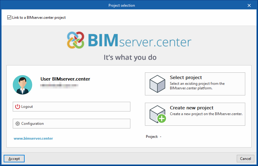
This is done in the "Project selection" window. On the left-hand side, you can log in with a BIMserver.center account.
- On the left-hand side, users can log in with a BIMserver.center account.
- On the right-hand side, the "Select project" option is used to choose an existing project. There is also the possibility to "Create a new project". In this case, the created project will be visible from BIMserver.centre from that moment on.
- The project can also be starting without being linked to the BIMserver.center platform. To do this, simply uncheck the box at the top left, "Link to a BIMserver.center project".
Once the new job has been created, the program interface is accessed, where the graphic window showing the model or models that have been imported stands out. At any time during the project, files can be shared or imported via the "BIMserver.center" group on the top right-hand side.
Importing BIM models
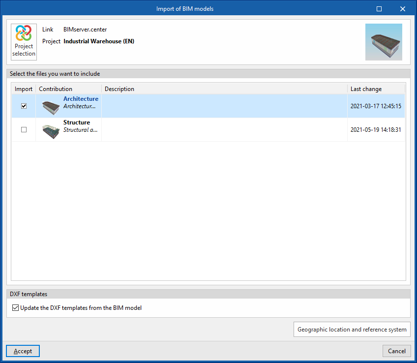
When creating a new job and selecting a project hosted on the BIMserver.center platform from "Select project", the "Import BIM models" window appears, which shows the files contained in that project in IFC format.
The program is able to include one or more of the existing models in the project. To do this, check the "Import" box and accept it.
When accessing the interface, the graphic window will display the imported models. Also, if they contain this information, the plan views needed to develop the system model will be imported and created.
| Note: |
|---|
| To load a different policy configuration later, or to consult or customise it, access the "Code configuration" in the "Project" group, in the top toolbar of the "Installation" tab. |
Configuration wizard: selecting standards, downloading catalogues and classifying spaces
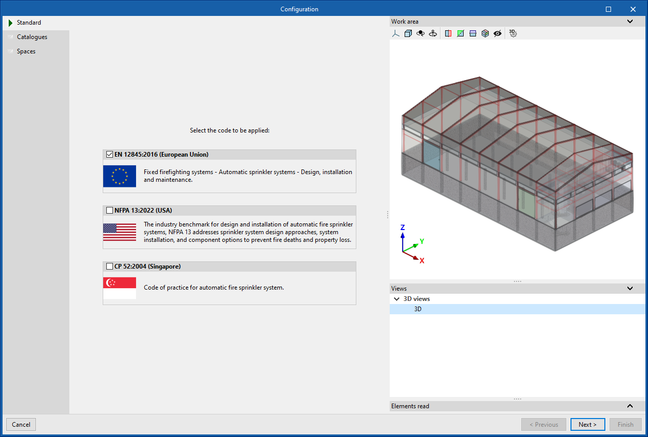
The program then opens the "Configuration" wizard, which consists of the following steps:
- In the first step, the applicable codes can be selected from those available for different countries and regions. The checks defined in the standard are then automatically imported.
| Note: |
|---|
| If you wish to subsequently load a different code configuration, consult it or customise it, you must access the "Code configuration" in the "Project" group, in the top toolbar of the "Installation" tab. |
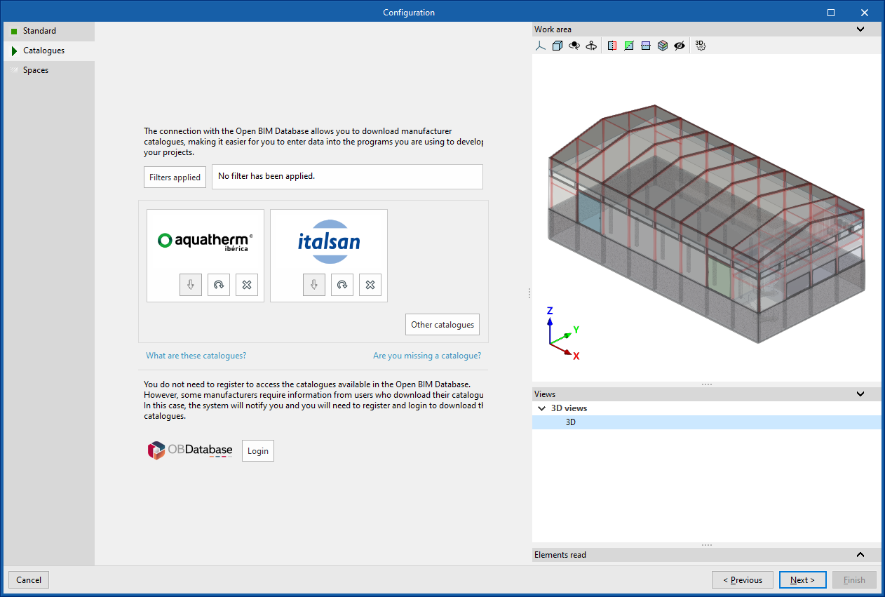
- In the next step, the connection to the Open BIM Database can be established in order to download and manage manufacturer catalogues. These catalogues will be available at the time of entering the elements in the system.
| Note: |
|---|
| To manage the job's catalogues at any time, use the "Catalogue management" option in the "Project" group in the top toolbar of the "Installation" tab. |
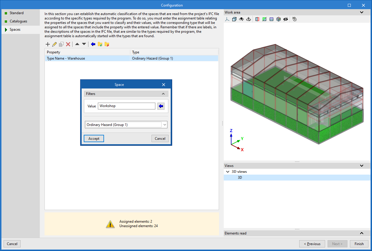
- Finally, in the last step you can set the automatic classification of the spaces read from the project’s IFC file according to the specific typologies required by the program.
To do this, entries must be added to the assignment table manually (using the "Add" button) or via the wizard.
In each entry, the spaces to be classified are filtered by specifying the values of their properties (in the "Value" parameter), and the room typology defined by the program that you wish to assign to them is selected (by activating the "Requires sprinkler system" box and choosing a specific room typology). In addition, you can indicate whether "Sprinkler protection above the false ceiling" will be included by activating the corresponding box and entering the "Air void height" value (in which case the "2 layers" column will be marked in the list).
You can also use the wizard in the upper toolbar to perform a joint import of all the spaces read in the IFC file based on the desired property, thereby generating one table entry for each group of spaces with the same property (which can then be adjusted by clicking the "Edit" option).
On the right, the program allows you to view the layout of the selected spaces in the model.
Any spaces that you do not intend to calculate must be removed from this classification table.
The program will assign the selected space type to all the rooms read from the IFC file that have the value indicated in the property shown in the wizard, and it will generate the geometry of the zones, adding them to the model view.
| Note: |
|---|
| If the spaces read from the BIM model need to be re-sorted, the "Update" option in the "BIMserver.center" group, also in the top toolbar of the "Installation" tab, can be used. In addition, to generate them again in the model, use the "Generate" option in the "Spaces" group. |
Additionally, it will read the position of the fire hose cabinets and the inlet and/or outlet points of dry and wet risers defined in the IFC file, from which the corresponding elements can be introduced using the program’s own options. It will also read the geometry of model elements such as beams and columns, allowing a collision analysis with the installation elements during the calculation.