Defining pressure differential systems
Within the "3D Model" group in the main toolbar, there is an option to define pressure differential systems:

Systems
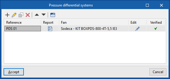
This opens the "Pressure differential systems" window. In the table that appears, pressure differential systems can be created, edited, copied, deleted and reordered.
The systems generated using the "Generate" option in the "Analysis" group are also displayed here.
-Automatically generating the pressure differential systems from the elements arranged in the work area. In this case, the reference of the systems (not yet defined in the "3D Model", "Systems" table) can be written directly in the elements of the model. Then, from "Analysis", "Generate", the systems can be generated from the information entered in the elements. The generated systems appear in the "3D model", "Systems" table as a consequence, with the updated information of the elements that are assigned to them.
-Manually defining pressure differential systems and updating them based on the elements arranged in the work area. The systems can first be created in the "3D model" table, "Systems". This can be done in a simplified form using the corresponding option ("Simplified entry of a pressure differential system"). Subsequently, the systems are assigned to the elements arranged in the model by editing them ("Edit", "Edit"). Later, the "Generate" option in the "Calculation" group can be used to update the required information in the "Systems" table.
-Defining pressure differential systems numerically. Systems can also be created and defined directly using the "3D model", "Systems" table, by entering all data numerically, without elements arranged in the work area and therefore without the geometry of spaces and the linking to a BIM model. As in the previous point, this can be done simply by using the corresponding option ("Simplified entry of a pressure differential system").
Pressure differential systems
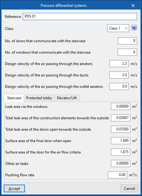
When creating or editing a pressure differential system, the following parameters need to be configured.
These parameters are generated automatically by using the "Generate" option in the "Calculation" group, and are filled in from scratch when creating the system in case of using the "Generate all systems" option, or by updating their values in case of using the "Generate incorrect systems only" option.
- Reference
- Class (Class 1 / Class 2)
- No. of doors that communicate with the staircase
- No. of windows that communicate with the staircase
- Design velocity of the air passing through the aerators
- Design velocity of the air passing through the ducts
- Design velocity of the air passing through the outlet aerators
"Staircase" tab
Defines the parameters associated with the staircase:
- Leak area via windows
- Total leak area of building elements towards the outside
- Total leak area of doors open towards the outside
- Surface area of the final door when open
- Surface area of the door for the air flow criteria
- Other air leaks
- Flushing flow rate
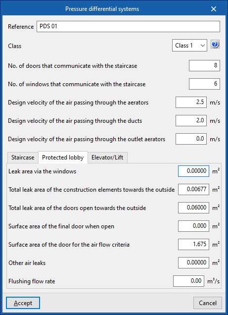
"Protected lobby" tab
Defines the parameters associated with the protected lobby:
- Leak area via windows
- Total leak area of building elements towards the outside
- Total leak area of doors open towards the outside
- Surface area of the final door when open
- Surface area of the door for the air flow criteria
- Other air leaks
- Flushing flow rate
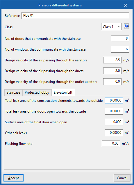
"Lift" tab
Defines the parameters associated with the lift:
- Total leak area of building elements towards the outside
- Total leak area of doors open towards the outside
- Surface area of the final door when open
- Other air leaks
- Flushing flow rate
Simplified entry of a pressure differential system
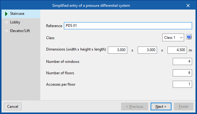
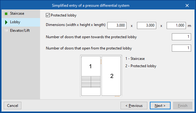
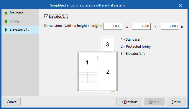
This option, located above the table in the "Pressure differential systems" window, opens a wizard that allows you to generate a pressure differential system by entering your data in a simplified form, indicating the parameters of the staircase, the protected lobby and the lift, where present.
Staircase
- Reference
- Class (Class 1 / Class 2)
- Dimensions (width x height x length)
- Number of windows
- Number of doors
- Accesses per floor
Lobby
- Protected lobby (optional)
- Dimensions (width x height x length)
- Number of doors that open towards the protected lobby
- Number of doors that open from the protected lobby
Lift
- Lift (optional)
- Dimensions (width x height x length)
When the wizard has finished, the pressure differential system will be created and displayed in the table. Users can edit the parameters of this system freely if necessary.
Fan selection
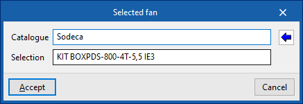
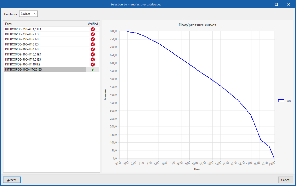
For each system, the program selects a fan that meets the minimum requirements of the assigned pressurisation system using the option available in the "Edit" column.
- Catalogue
- Selection
The button on the right selects a fan from the available manufacturer catalogues. These catalogues can be loaded from the "Catalogues" option in the "Project" group in the program's general interface.
The "Fan" column shall show the fan reference of the selected fan.
The "Complies" column shall indicate whether the selected fan complies with the specifications required by the system.
On the right, the curve relating the flow rate and the fan operating point pressure is shown.
If a fan is available in the model and assigned to the system, its representation will be updated after the fan has been selected. If not, the fan can now be arranged via the "Fan" option in the "3D model" group by selecting the corresponding system.


