Automatic generation of the air-conditioning system
The program includes a number of tools that enable the automatic layout of various parts of the air-conditioning system. The geometry generated by the automatic layout process can be adjusted and modified subsequently to suit the project’s requirements.
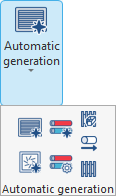
The options for automatic generation can be found in the "Automatic generation" group, under the "3D Model" tab:

Clicking on the "Automatic generation" option opens a menu with the following options:
- Duct with grilles
- Duct with diffusers
- Water distribution
- General options
- Generate vertical risers
- Horizontal offset
- Vertical offset
The first two options, "Duct with grilles" and "Duct with diffusers", allow for the automatic routing of these parts of the ducted air distribution system between the points in the work area specified by the user, without the need to import a 3D model from BIMserver.center that includes spaces, nor is it necessary to have entered any vertical or horizontal offsets.
The remaining options relate to the automatic generation of water pipes that connect hydronic units (such as heat pumps or fan coils). To use these options, you must have imported a 3D model of the project from BIMserver.center that includes spaces and doors; and, if necessary, you must have generated or entered vertical or horizontal offsets, which the program takes into account during this pipe generation process.
Duct with grilles
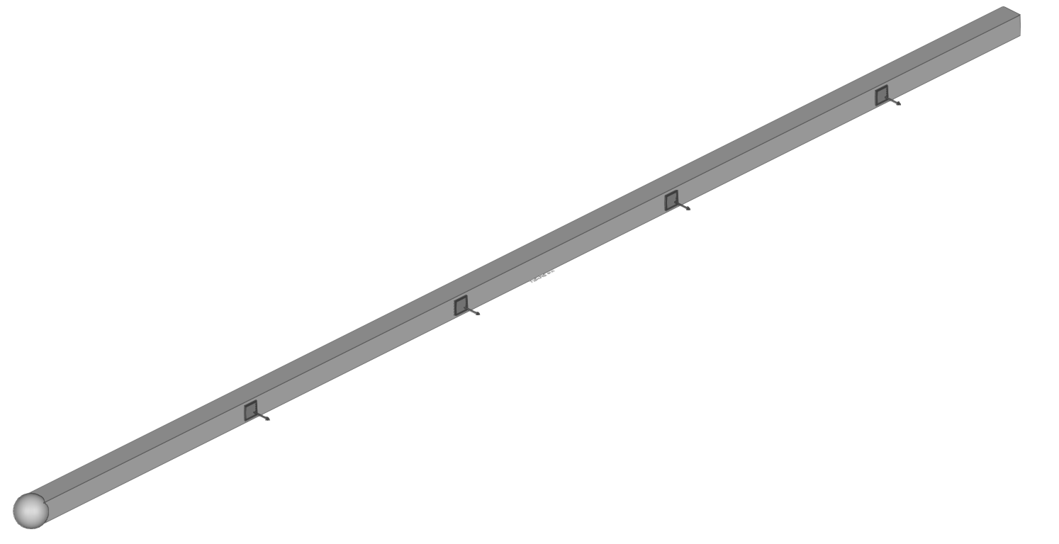
The "Duct with grilles" option lets you create a rigid duct with evenly spaced grilles.
In the panel that appears when you click on the option, you can specify the type of "Grid" and the "Spacing between grids", as well as the type of "Rigid duct".
The available configuration options are identical to those that appear when you enter these elements individually using the relevant tools.
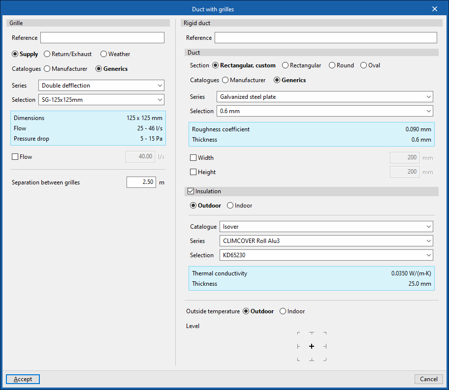
Next, two points must be marked on the "Work area" to position the duct.
The program will generate a rigid duct with grilles of the selected types at the specified spacing from the first point, positioned on the right-hand side of the duct as shown in the drawing. It will also generate a "Initial point of the duct pre-installation" at the first point entered.
Duct with diffusers
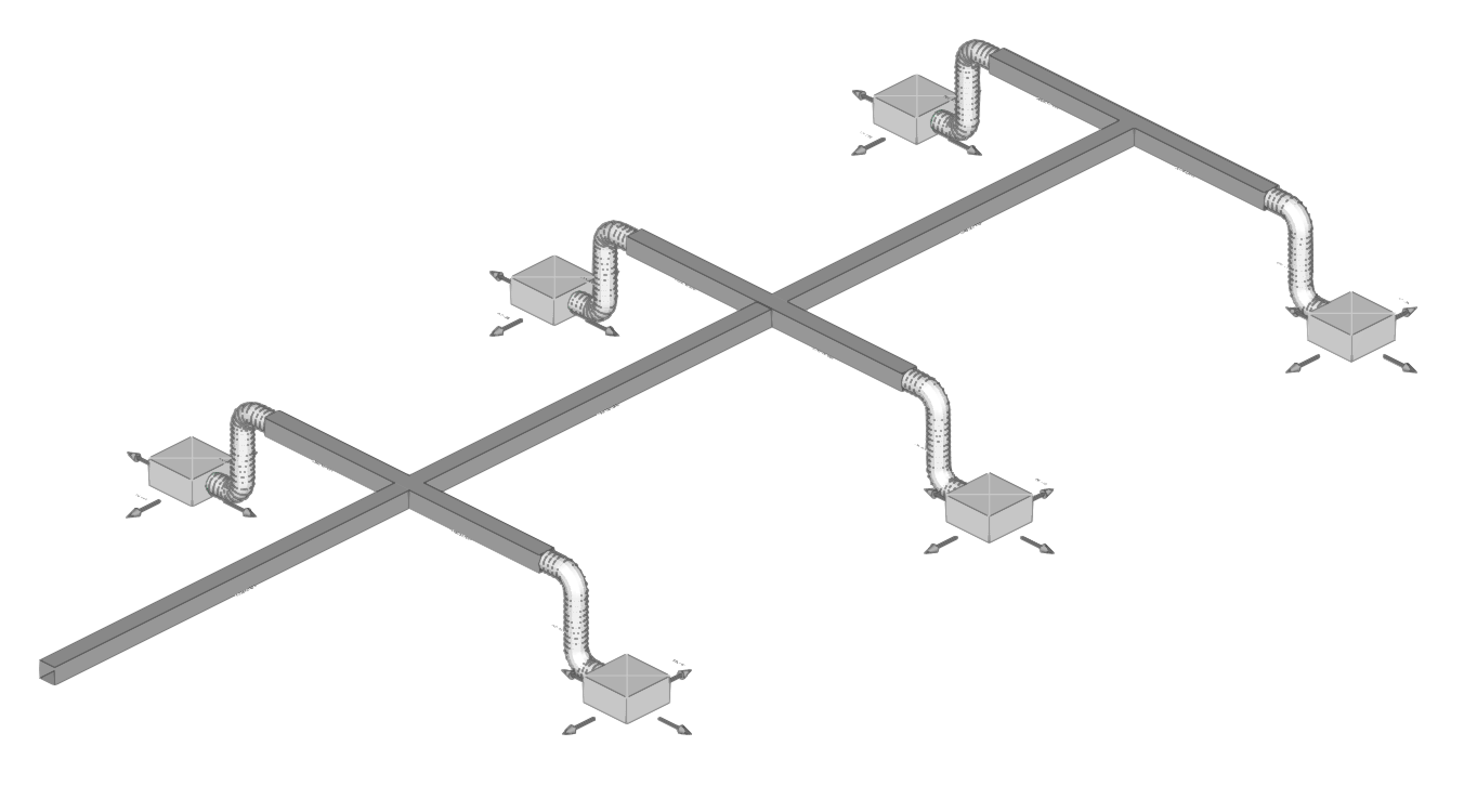
The "Duct with diffusers" option lets you create a network of rigid ducts, flexible ducts and diffusers.
In the panel that appears when you click on the option, you can specify the type of "Diffuser" and the "Height difference between the rigid duct and the diffuser", as well as the type of "Rigid duct".
The available configuration options are identical to those that appear when you enter these elements individually using the relevant tools.
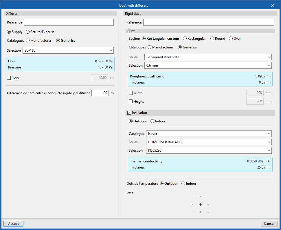
Next, two points must be marked on the "Work area" to position the duct.
The program will generate an air distribution network comprising the following elements:
- A rigid conduit between the selected points.
- Branches of rigid conduits on both sides, running perpendicular to the previous one and separated by a predetermined distance.
- The installation of horizontal flexible ducts between the ends of the rigid duct branches and the diffusers.
- Diffusers at the network’s end points.
Water distribution
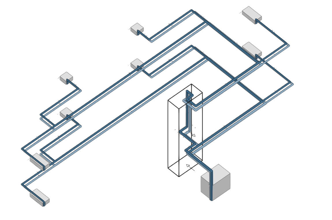
The "Water distribution" option generates the water pipes for the HVAC system, connecting the hydronic components of the system that have been previously placed in the model (such as heat pumps or fan coils).
The procedure for automatically generating distribution networks between elements is as follows:
- Firstly, you must prepare the model, ensuring that the following has been done:
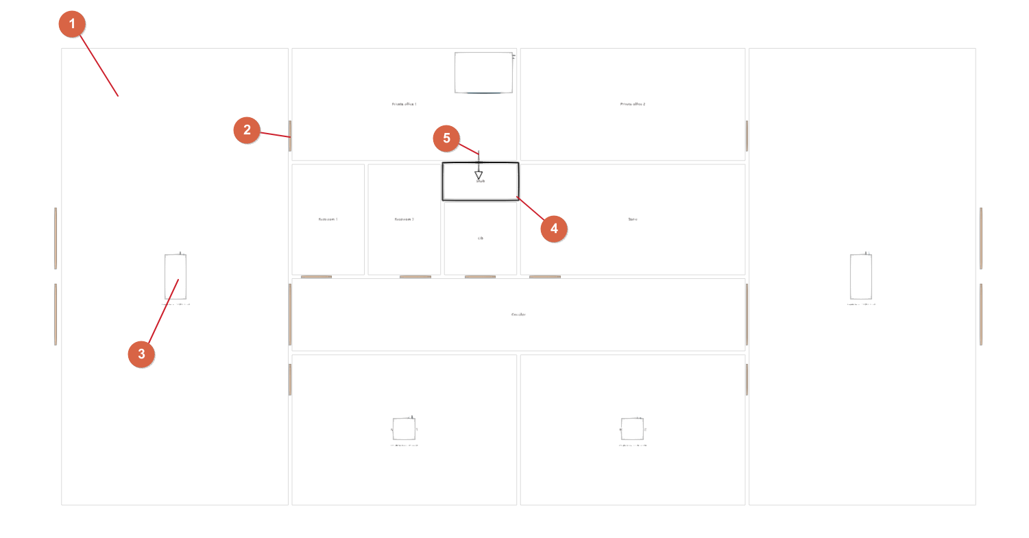
- By importing spaces (1) from the BIM model, the necessary spaces are created and assigned. Spaces must exist at all the points through which you wish to generate the network, as the program will use them during the generation process to define the route of the distribution network.
- During the data-reading process, the doors (2) from the geometric model are also imported; these will be used by the program to define the network layout.
- The hydronic equipment (3) to be connected (heat pumps, fan coils, etc.) must be positioned within the space. This equipment must be physically located inside the designated spaces.
- Vertical steps (4) must also be generated or positioned, either by importing the BIM model and mapping the spaces as vertical steps, and then using the "Generate vertical steps” option, or by placing them manually where required using the "Vertical step” option in the "Generation” menu.
- Similarly, a "Horizontal offset" (5) of pipework can be created using the "Generate" menu option at each point where such a run is to be permitted; for example, at all entry or exit points of a vertical run through a partition wall (by default, the program will use the doors to generate the pipework geometry if no horizontal offsets exist).
- Secondly, click on the "Water distribution" option in the "Generation" menu. Here, you need to:
- Define the tree structure of the water distribution network (using the "Add" option and the other available tools). To add multiple source points to the structure (for example, a system with several heat pumps), simply define several initial levels within the same hierarchy:
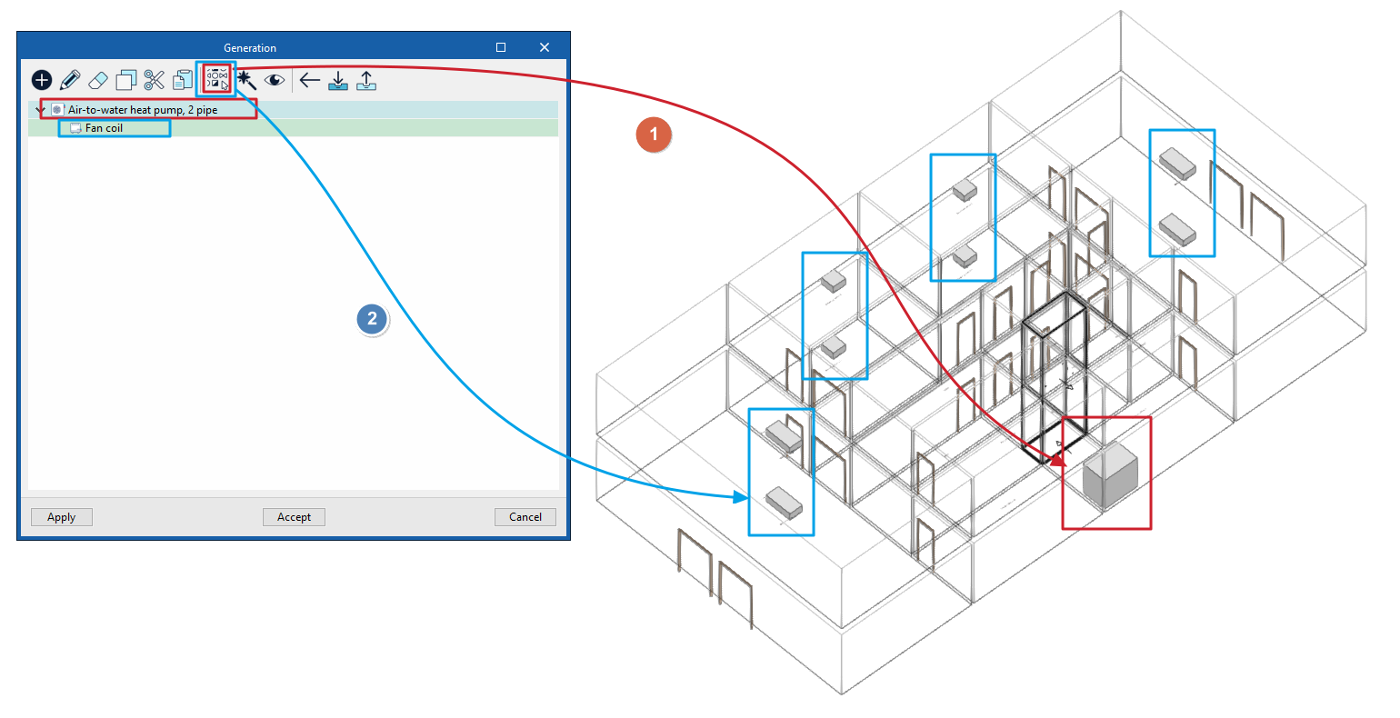
- For example, in a system comprising a single heat pump connected to several fan coils, a level called "Air-to-water heat pump, 2-pipe" is defined, and, in the hierarchy below that, a single level called "Fan coil".
- Assign the model elements that correspond to each level of the tree (using the "Select" option to do this manually, or the "Group automatically" option to let the program carry out the operation). You can select multiple pieces of equipment to assign to each of the levels.
- Define the tree structure of the water distribution network (using the "Add" option and the other available tools). To add multiple source points to the structure (for example, a system with several heat pumps), simply define several initial levels within the same hierarchy:
- Finally, once the tree has been defined and the elements assigned, the water distribution network is generated by clicking on the "Apply" option in the "Generation" window and confirming with the left mouse button.
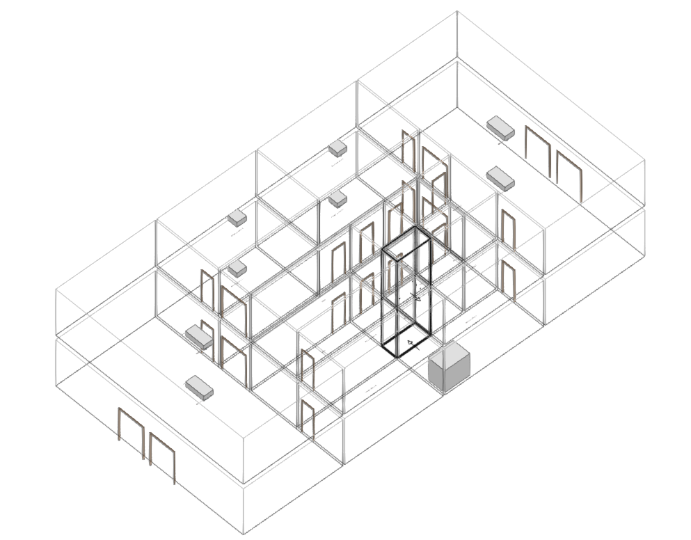
You can return to the network tree at any time to add new levels and select items for them. When you click "Apply" again, the newly added part of the installation will be generated.
"Generation" window
The "Generation" window appears when you click on the "Water distribution" option and displays the water distribution system tree.
Levels that have been associated with elements in the model are shown in green, whilst those that have yet to be associated are shown in red.
This window also allows you to edit the installation tree manually using the various tools available at the top:
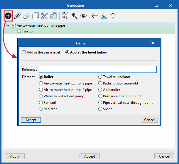
- Add
Add a level to the installation tree. You can:- "Add at the same level" or "Add at the level below".
- Enter the "Reference’ for the level.
- Select the "Element" corresponding to the level from the following:
- Boiler
- Air-to-water heat pump, 2 pipe
- Air-to-water heat pump, 4 pipe
- Water-to-water heat pump
- Fan coil
- Radiator
- Towel rail radiator
- Radiant floor manifold
- Air handler
- Primary air handling unit
- Pipe vertical pass-through point
- Space
- Edit
Edit the "Reference" and the "Element" type associated with the selected level in the tree. - Delete
Delete the selected layer. - Copy / Cut / Paste
Copy, cut or paste the selected level, together with all its sub-levels, into the tree. - Select
Select elements from the model (either hydronic units or vertical runs) and associate them with the selected level in the tree. - Group automatically
The program analyses the model and automatically associates the model elements with the levels of the installation tree. - Show elements
Highlights the model elements in the "Workspace" assigned to the selected tree level. - Import the elements saved in the drive to the project
Select a file with the .bib956 extension containing the installation tree information and import it into the program.- If "Assign selecting elements manually" is enabled, the user must select the model elements manually to associate them with the different levels of the generated installation tree. If this option remains disabled, the program will automatically assign elements from the model to the different levels of the generated installation tree.
- Export the element to a file
Export the information from the installation tree created in the program to a file with the .bib956 extension, which is saved to disk.
The "Generation" window has three options at the bottom:
- Apply
Generate the pipe sections for the water distribution system in the model based on the diagram created and the element associations made. The program displays a preview of the generated geometry. Clicking the left mouse button anywhere in the "Work area" will complete the generation of the pipe spans. From this point onwards, you can freely modify the generated system to suit the project’s requirements. If, on the other hand, you right-click the mouse, the generation is cancelled, and the program returns to the "Generation” window. - Accept
Accept the changes made to the installation tree structure and close the window. - Cancel
Cancel the changes made to the installation tree structure and close the window.
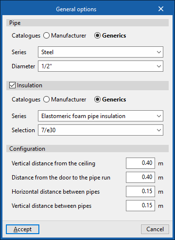
General options
These options let you configure and select the materials used in the pipe generation process:
- Pipe
Select the material series used in the pipes created during the generation processes.- Catalogues (Manufacturer / Generic)
- Insulation (optional)
Specify whether the pipes created during the generation processes are insulated and, if so, the material grades used in them.- Catalogues (Manufacturer / Generic)
- Configuration
Configure the distance between pipes and walls, doors or between pipes themselves during the generation process:- Vertical distance from the ceiling
- Distance from the door to the pipe run
- Horizontal distance between pipes
- Vertical distance between pipes
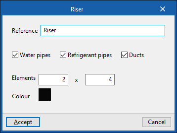
Generate vertical passages
This option lets you automatically generate the geometry of a vertical passage based on the selection of a space read from the model (associated with a space type that permits "Pipe passages").
During the process, the following details must be entered:
- Reference
Step reference. - Water pipes (optional) / Refrigerant pipes (optional) / Ducts (optional)
Selecting these options specifies the types of elements that can be placed in the passage. - Elements (m × n)
Number of element positions available in the vertical passage. - Colour
Representation colour.
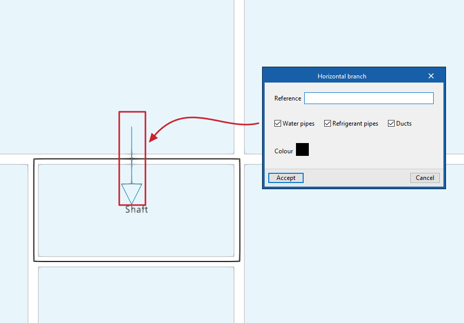
Horizontal passage
This lets you specify or override the horizontal passage of water pipes, refrigerant pipes or vertical ducts created during the generation process.
This element can be positioned between two spaces or between a vertical passage and a space.
When entering a horizontal pipe run, the following details must be provided:
- Reference
Passage reference. - Water pipes (optional) / Refrigerant pipes (optional) / Ducts (optional)
Selecting these options specifies the types of elements that can be placed in the passage. - Colour
Representation colour.
Two horizontal passages can be added in either direction if necessary.
If there are horizontal steps, the program will attempt to use their position to generate the pipe layout, making the pipes run over them, rather than using the position of the doors in the BIM model.
Vertical passage
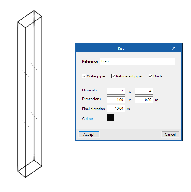
Specify the position of a riser or vertical passage of water pipes, refrigerant pipes or vertical ducts installed as part of the generation process.
When entering a vertical passage, the following details must be provided:
- Reference
Passage reference. - Water pipes (optional) / Refrigeration lines (optional) / Ducts (optional)
Selecting these options specifies the types of elements that can be placed in the passage. - Elements (m × n)
Number of element positions available in the vertical passage. - Dimensions (a x b)
Floor plan dimensions of the vertical passage. - Final elevation
Final elevation of the vertical passage in absolute coordinates. - Colour
Representation colour.
Next, the step is inserted into the "Workspace" by selecting a point on the model.
The starting position of the vertical step can be controlled using the "Move" option in the "Edit" group.
If the vertical passage is not physically located within another space (with its geometry partially overlapping), horizontal runs must be used to indicate the exit and/or entry points of the distribution network elements.