Defining the project characteristics
In the "Project" group in the main toolbar, the following project data can be defined:

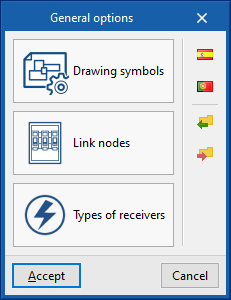
General options
Allows users to define the system's general options or to import them from the following code specifications:
Options
- Drawing symbols
- Link nodes
- Types of receivers
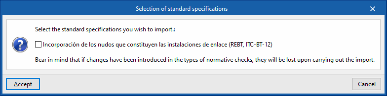
Selection of standard specifications
- Spain
- Incorporación de los nudos que constituyen las instalaciones de enlace (REBT, ITC-BT-12)
- Portugal
- Incorporação dos nós que constituem as instalações colectivas e as entradas (RTIEBT, Parte 8 / Secção 803)
Details on the above-mentioned facilities are given below.
Drawing symbols
The "Configuration" window is used to define the symbols to be used in the system drawings.
There are three tabs:
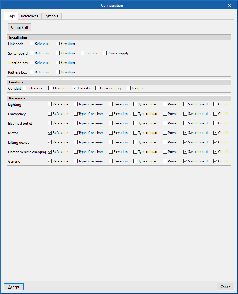
- Tags
Allows users to activate or deactivate the information that appears in the element's tags:- Installation
- Link node (reference, elevation)
- Switchboard (reference, elevation, circuits, power supply)
- Junction box (reference, elevation)
- Pattress box (reference, elevation)
- Conduits (reference, elevation, circutis, power supply, length)
- Receivers (reference, type of receiver, elevation, type of load, power, switchboard, circuit)
- Installation
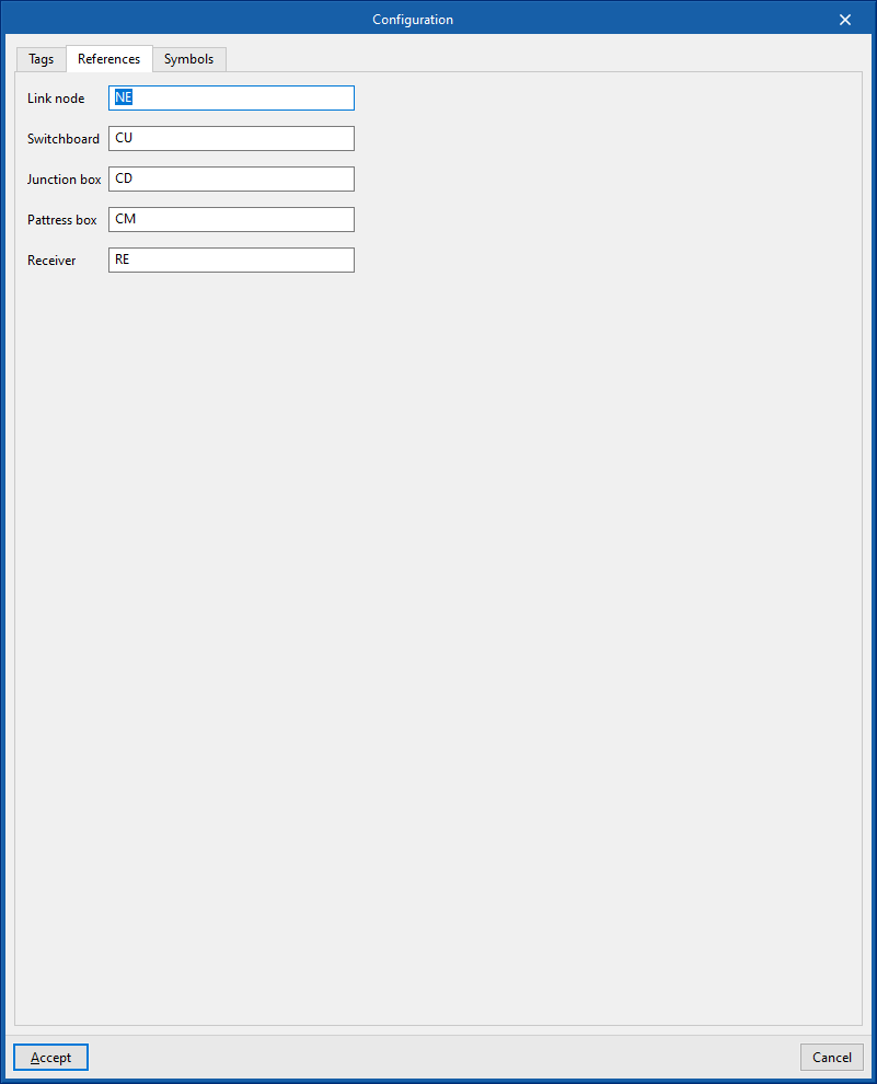
- References
Configures the reference text of the elements:- Link node
- Switchboard
- Junction box
- Pattress box
- Receiver
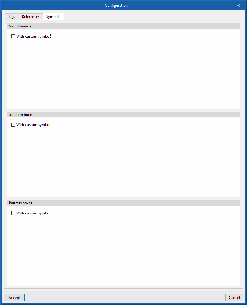
- Symbols
Allows users to design the symbols of the following elements by means of lines, areas, arcs, circles and text boxes:- Switchboards
- Junction boxes
- Pattress boxes
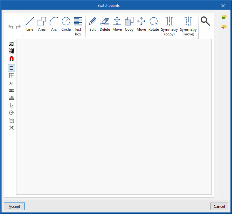
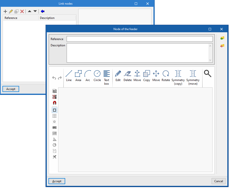
Link nodes
Allows the design of the link node symbols to be carried out manually or imported from files on disk:
- Designing symbols through lines, areas, arcs, circles and text boxes
- Importing symbols from DXF/DWG and DWF files
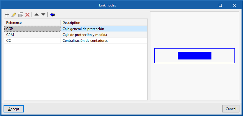
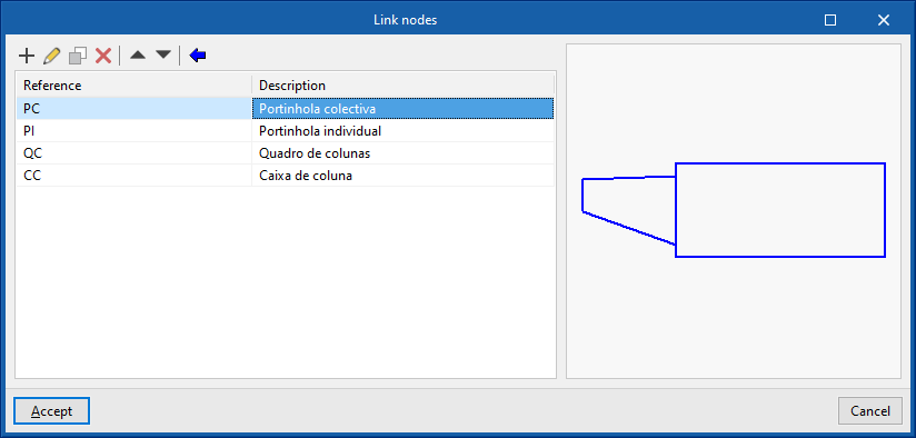
The link node types defined here can be loaded later by using the "Link nodes" option in the main toolbar.
This information can be generated automatically by selecting the regulatory specifications of the desired country:
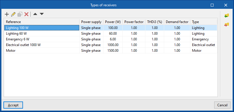
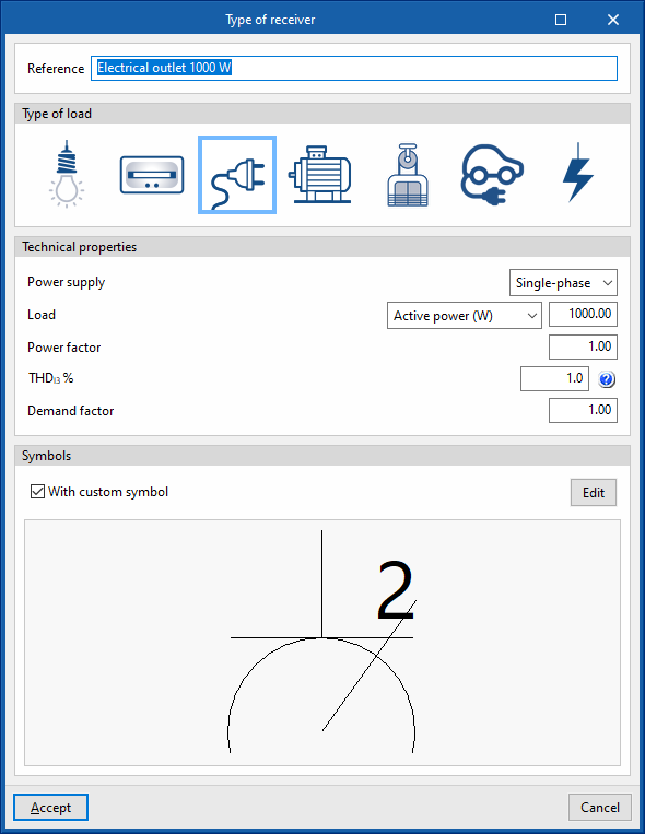
Types of receivers
Allows the types of receivers to be defined by specifying the following parameters:
- Reference
- Type of load (lighting, emergency, electrical socket, motor, lifting device, electric vehicle charging, generic)
- Technical properties
- Symbols
The types of receivers defined here can be loaded later when using the "Receivers", "Assign receivers" or "Assign properties" options in the main toolbar.
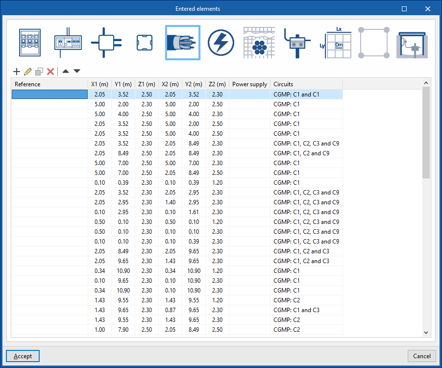
Entered elements
Allows users to consult and modify the data of the elements entered in the model in a series of tables that include the following information:
- Link nodes: reference, X, Y, Z, angle, type of node, power supply (upstream)
- Switchboards: reference, X, Y, Z, angle,
- Junction boxes: reference, X, Y, Y, Z, angle
- Pattress boxes: reference, X, Y, Y, Z, angle
- Conduits: reference; X1, Y1, Z1 (coordinates of start point); X2, Y2, Z2 (coordinates of end point); power supply; circuits
- Receivers: reference, X, Y, Z, angle, switchboard, circuit, overview
- Buried conductor: reference; X1, Y1, Z1 (coordinates of the starting point); X2, Y2, Z2 (coordinates of the end point)
- IEC electrode: type, X, Y, Z, angle X, angle Y, angle Z
- IEEE grid: reference, X, Y, Z, angle X, angle Y, angle Z
- UNESA grid: reference, X, Y, Z, angle X, angle Y, angle Z
- Grounding box: reference, X, Y, Z, angle X, angle Y, angle Z
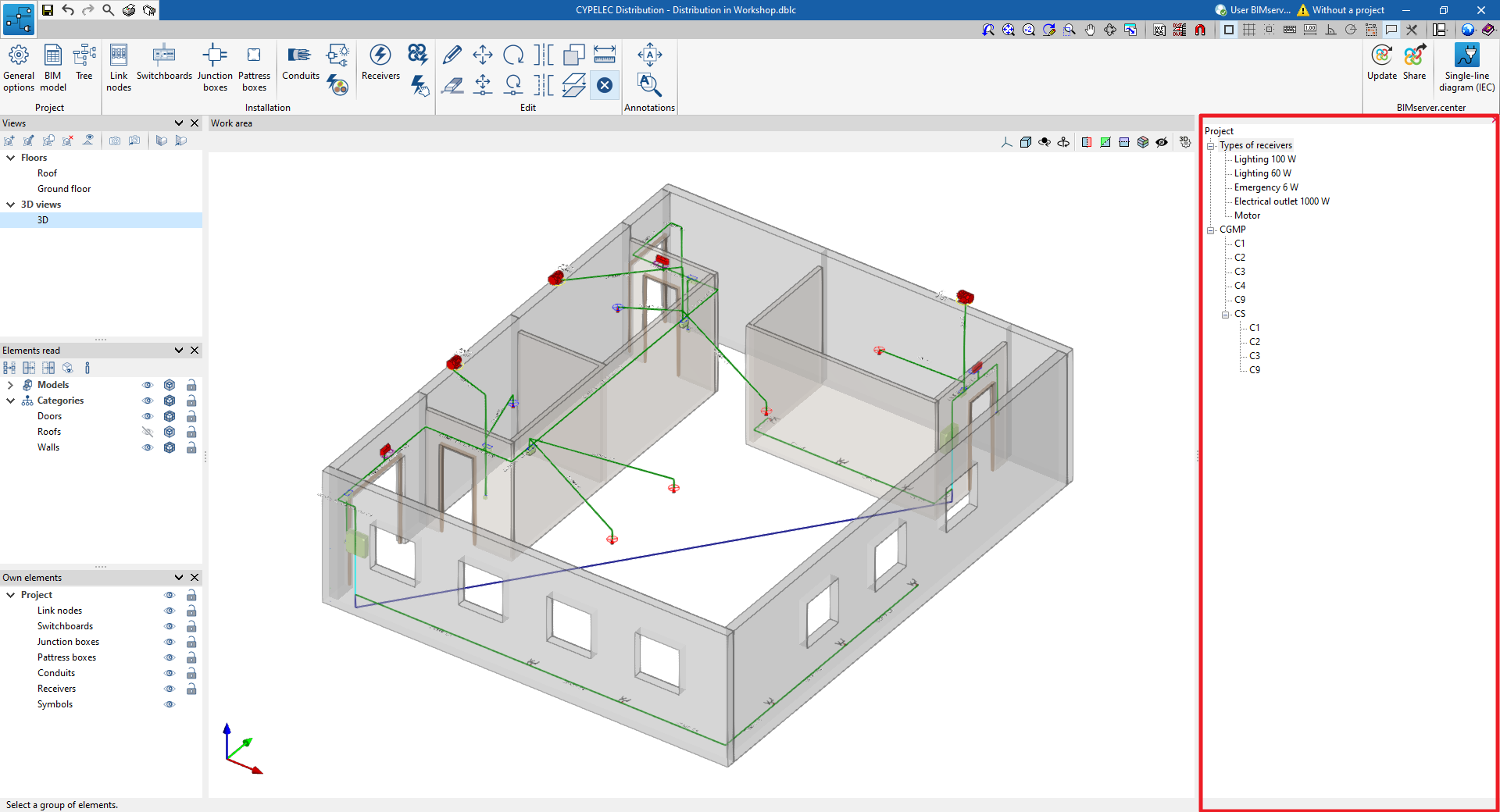
Tree
Allows users to check the elements entered in the model in a drop-down tree of project components on the right-hand side of the screen.
When selecting each component, they light up in red on the model.
Grounding system
Access to a window with the list of available grounding systems. These systems can be selected when entering the grounding components in the geometrical model using the options in the "Grounding" group of the upper toolbar.
The information on the different grounding systems defined can be exported to the BIM project and subsequently used in programs such as CYPELEC.
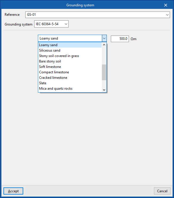
When creating a grounding system, the following parameters are indicated:
Defining a grounding system IEC 60364-5-54
- Reference
- Grounding system: IEC 60364-5-54
- Type of soil
- Soil resistivity (Ωm)
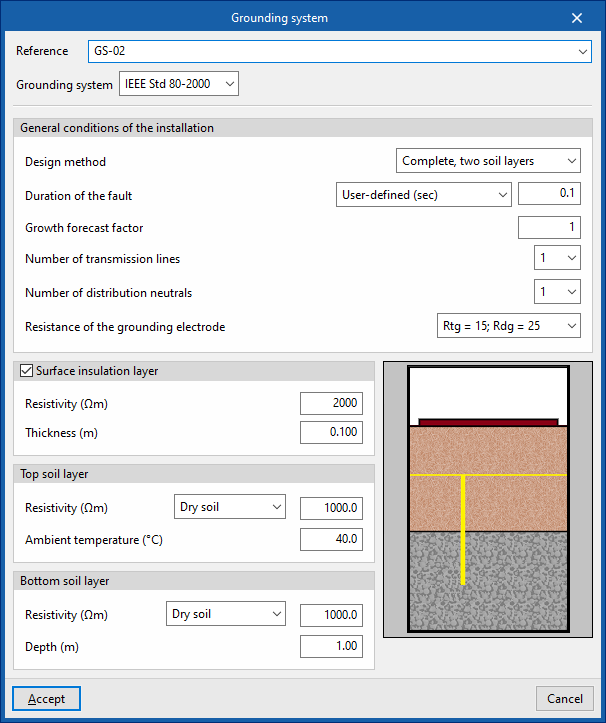
Defining a grounding system IEEE Std 80-2000
- Reference
- Grounding system: IEEE Std 80-2000
- General conditions of the installation
- Design method (Simplified / Complete, homogenous soil / Complete, two soil layers)
- Duration of the fault (User-defined / Provided by the protection)
- Growth forecast factor
- Number of transmission lines
- Number of distribution neutrals
- Resistence of the grounding electrode
- Surface insulation layer (optional)
- Resistivity (Ωm)
- Thickness (m)
- Top soil layer
- Resistivity (Ωm)
- Ambient temperature (ºC)
- Bottom soil layer (in the design method "Complete, two soil layers")
- Resistivity (Ωm)
- Ambient temperature (ºC)