Entering groups and lines
In the "Lines" group of the main toolbar, either in the "Single line" tab or in the "Tree" tab, the following elements can be defined and entered:

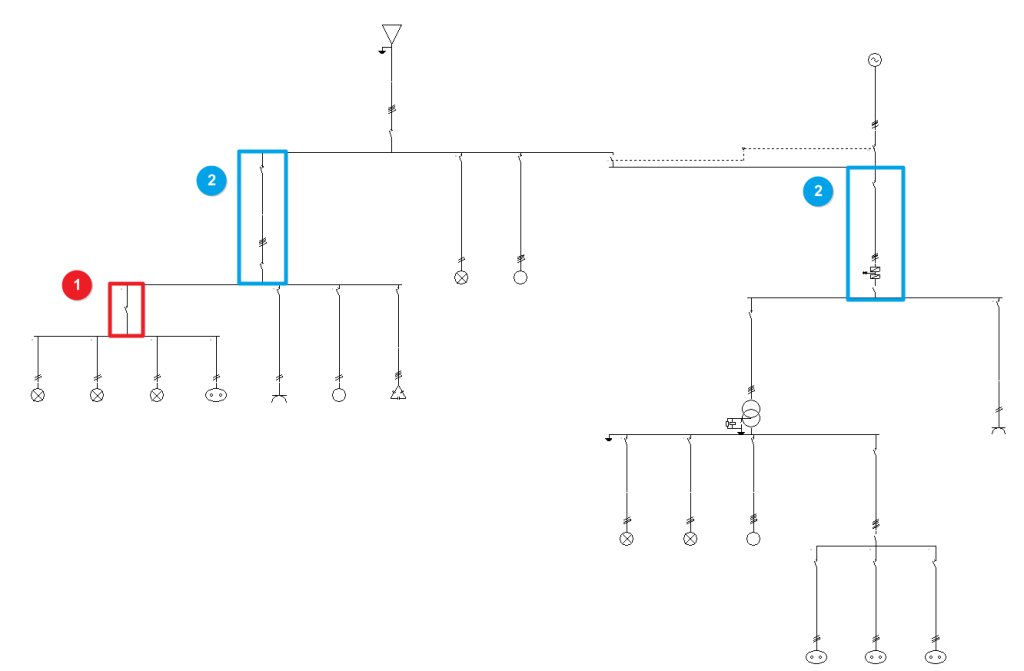
The program is highly versatile in the layout of electrical system diagrams in terms of the number of elements, nesting of levels and types of load. The groups and lines are organised based on the multilevel supply and collect the distributed or concentrated load circuits, downstream:
- Group (1)
- Line (2)
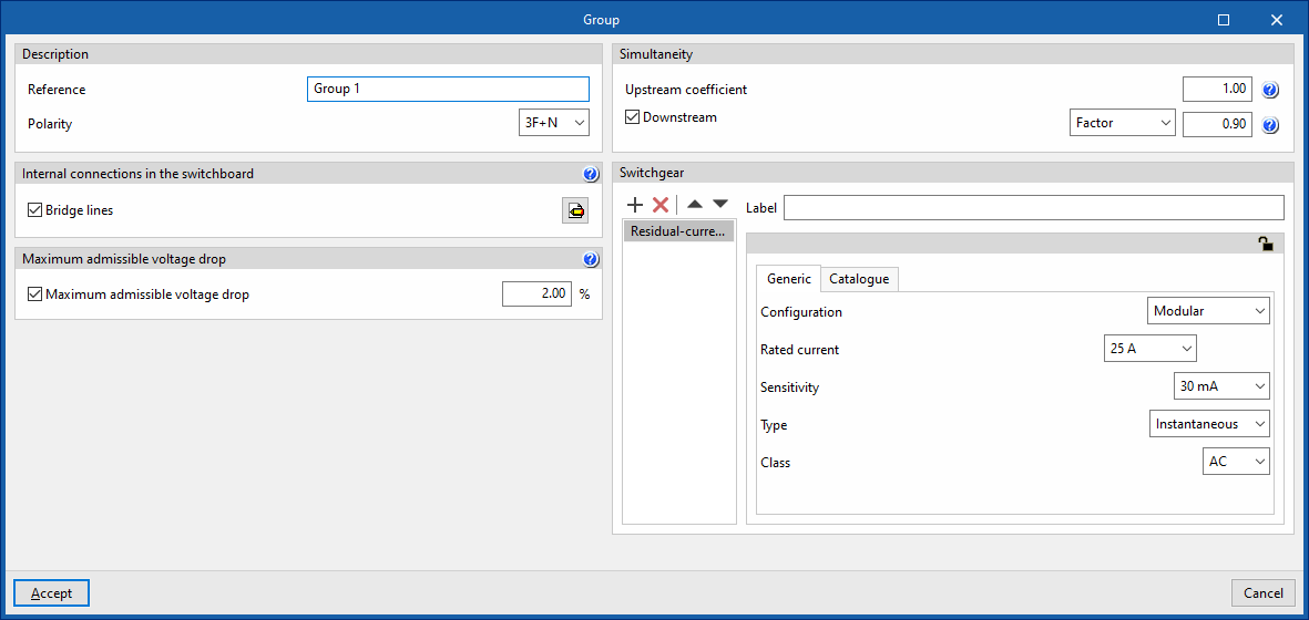
Group
Allows users to define and enter a group of different loads using one or more protection elements but without a conduit. No length value definition is required. Clicking on the option opens the "Group" window, which displays the following configuration options:

- Description
- Reference
- Polarity
- Internal connections in the switchboard
- Bridge lines (optional)
By activating this option, the program allows users to enter and consider bridge lines in the group. It opens the "Bridge lines" window, with the following options:- Bridge lines to consider and their lengths
- Inlet (optional)
- Between switchgear (optional)
- Outlet (optional)
- Conductor (optional)
- Cable
- Reference installation method
- Specific reference installation method (optional)
- Bridge lines to consider and their lengths
- Bridge lines (optional)
- Maximum admissible voltage drop
- Maximum admissible voltage drop (optional)
With this option, users can set a maximum admissible voltage drop value. The program will check and design the line according to the value entered.
- Maximum admissible voltage drop (optional)
- Simultaneity
These options allow users to define the simultaneity of the lines. - Switchgear
Allows users to enter the switchgear for the group. It may be one of the following types:- Circuit breaker
- Fuse
- Residual-current device
- Surge protector for transient overvoltages
- Sectionaliser
- Contactor
- Network analyser
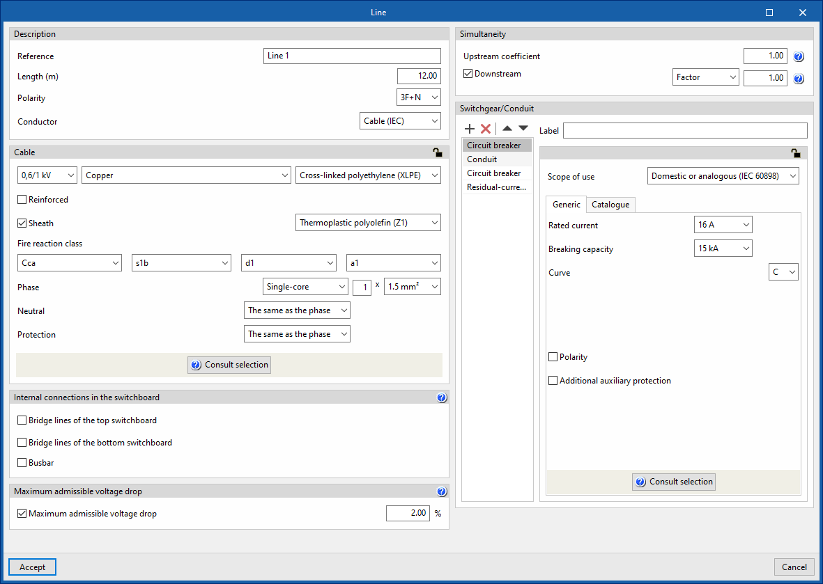
Line
Allows users to define and enter a line in the model. Clicking on the option opens the "Line" window, which displays the following configuration options:

- Description
- Reference
- Length (m)
- Polarity
- Conductor
- Cable
- Internal connections in the switchboard
- Bridge lines of the top switchboard (optional)
By activating this option, the program allows users to enter and consider bridge lines of the top switchboard on the line. It opens the "Bridge lines of the top switchboard" window, with the following options:- Bridge lines to consider and their lengths
- Inlet (optional)
- Between switchgear (optional)
- Conductor
- Cable
- Reference installation method
- Specific reference installation method (optional)
- Bridge lines to consider and their lengths
- Bridge lines of the bottom switchboard (optional)
By activating this option, the program allows users to enter and consider bridge lines of the bottom switchboard on the line. It opens the "Bridge lines of the bottom switchboard" window, with the following options:- Bridge lines to consider and their lengths
- Between switchgear (optional)
- Outlet (optional)
- Conductor
- Cable
- Reference installation method
- Specific reference installation method (optional)
- Bridge lines to consider and their lengths
- Busbar
By activating this option, the program allows users to enter and consider busbars on the line.
- Bridge lines of the top switchboard (optional)
- Maximum admissible voltage drop
- Maximum admissible voltage drop (optional)
With this option, users can set a value for the maximum admissible voltage drop. The program will check and design the line according to the value entered.
- Maximum admissible voltage drop (optional)
- Simultaneity
These options allow users to define the simultaneity of the lines. - Switchgear/Conduit
Allows the switchgear to be entered and the conduit of the line to be defined. This can be of the following types:- Circuit breaker
- Fuse
- Magnetic starter
- Residual-current device
- Surge protector for transient overvoltages
- Sectionaliser
- Switch disconnector
- Contactor
- Meter
- Network analyser
- Battery


