
Defining switchgear and conduits in lines and circuits
Switchgear and conduits can be defined in the "Switchgear/Conduit" section, located on the right-hand side of the editing panels for groups, lines, circuits, switchboards and special lines.
A table can be used to insert, delete or reposition different types of switchgear at the head or foot of each line.
The switchgear available in the program and the conduit definition options are as follows:
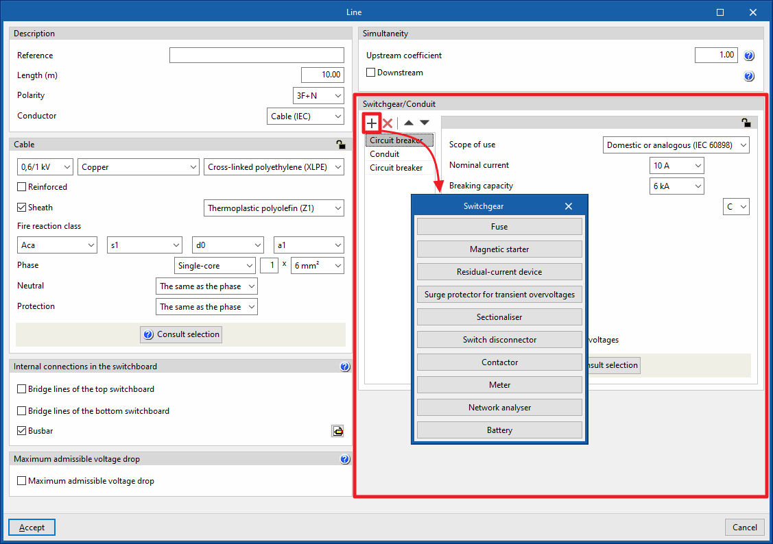
Circuit breaker
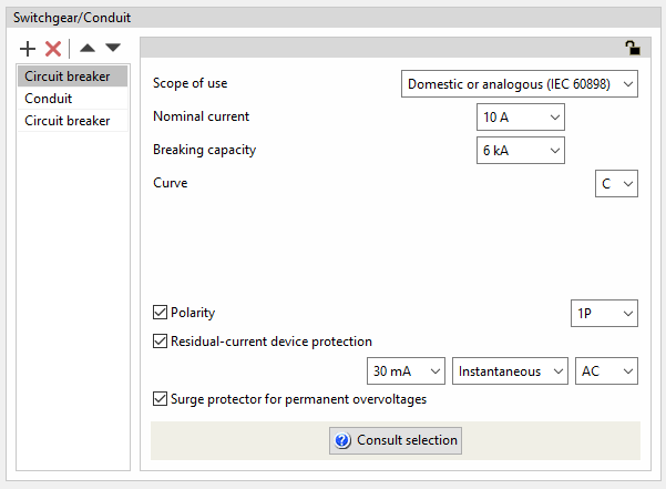
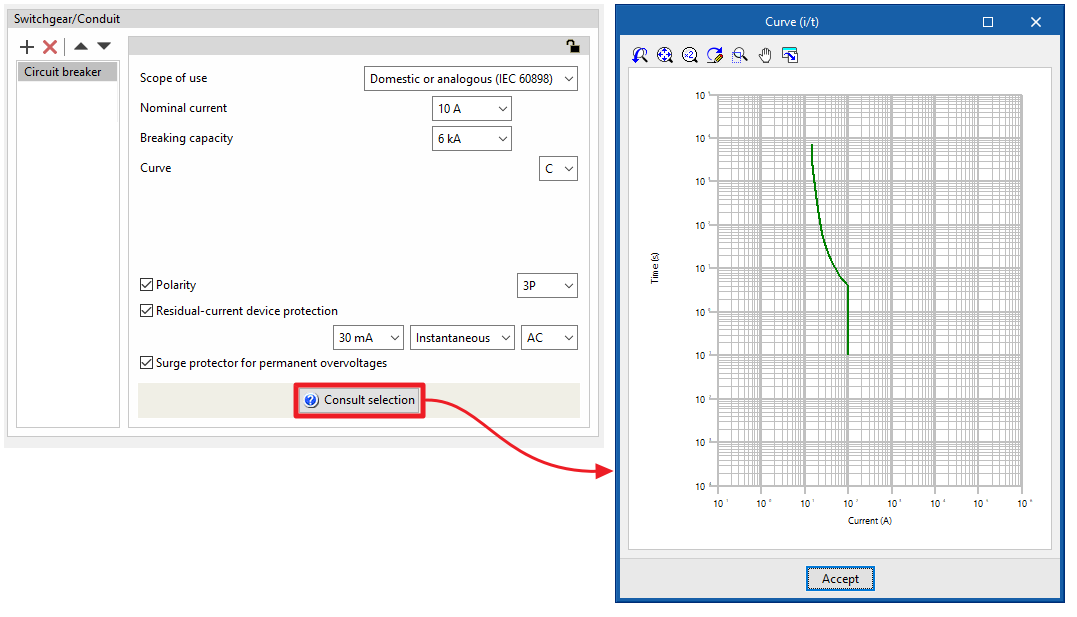
Circuit breaker protection is an element normally used to protect the line against overcurrents and short circuits. It is also possible to associate differential protection against indirect contact with the circuit breaker. The program allows circuit breakers to be added to groups, lines and domestic or analogue, tertiary or industrial circuits, indicating the following characteristics:
- Scope of use: Domestic or analogous (IEC 60898)
- Nominal current (A)
- Breaking capacity (kA)
- Curve
- Polarity (optional)
- Residual-current device protection (optional)
- Sensitivity
- Type
- Class
- Surge protector for permanent overvoltages (optional)
The nominal current of the residual-current device protection will be the same as the one defined in the circuit-breaker properties.
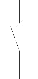
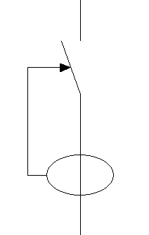
If the "Surge protector for permanent overvoltages" checkbox is activated, an icon will appear on the single-line diagram representing the coil system that is usually installed in circuit breakers to trigger them in the event of a fluctuation that increases the voltage value above the safety limit.
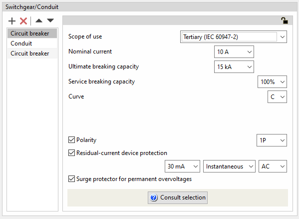
- Scope of use: Tertiary (IEC 60947-2)
- Nominal current (A)
- Breaking capacity (kA)
- Service breaking capacity (25% / 50% / 75% / 100%)
- Curve (B / C / D)
- Polarity (optional)
- Residual-current device protection (optional)
- Sensitivity
- Type
- Class
- Surge protector for permanent overvoltages (optional)
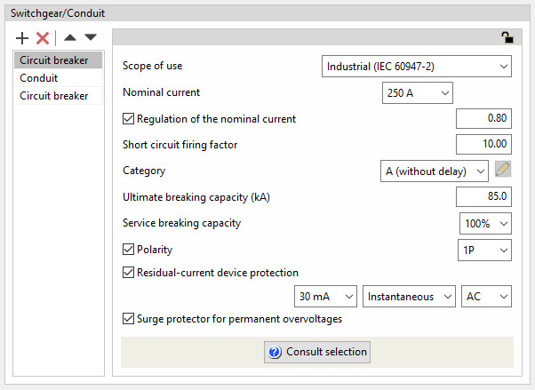
- Scope of use: Industrial (IEC 60947-2)
- Nominal current (A)
- Regulation of the nominal current (optional)
As well as setting the nominal current of the device, this value can be regulated by entering the regulation value in the switchboard.- Regulation factor of the rated current
- Short circuit firing factor
The short circuit firing factor shall define the position of the vertical part of the firing curve of the device as a result of multiplying the value of the regulated current by the short circuit firing factor. - Category
The device category is used to define the last step of the intensity/time graph.- A (without delay)
- B (with delay)
- Short delay period (s)
- Short-time current-carrying capacity (kA)
- Ultimate breaking capacity (kA)
- Service breaking capacity
It is set as quartiles of the ultimate breaking capacity:- 25% / 50% / 75% / 100%
- Curve (B / C / D)
- Polarity (opcional)
- Residual-current device protection (optional)
- Sensitivity
- Type (Instantaneous / Selective)
- Clase (AC / A / A 'Si' / B / B 'Si')
- Surge protector for permanent overvoltages (optional)
By clicking on the "Check selection" option, the intensity-time curve corresponding to the characteristics entered is displayed.
Residual-current device
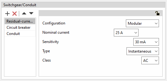
Residual-current device protection is used to protect a line against indirect contacts and leakage current losses. The program can be used to define residual-current device protection in a group, line or circuit with the following characteristics:
Modular residual-current device
- Configuration: Modular
- Nominal intensity (A)
- Sensitivity
- Type (Instantaneous / Selective)
- Class
- AC
- A
- A 'Si' (super-immunised)
- B
- B 'Si' (super-immunised)
- AC / A / A 'Si' / B / B 'Si')
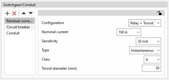
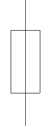
Residual current relays with toroids
To extend the selection of residual-current device protection with a higher nominal current, the program has the option to select residual-current device protection by means of a toroidal device linked to its corresponding trip relay.
- Configuration: Relay + Toroid
- Nominal intensity (A)
- Sensitivity
- Type (Instantaneous / Selective)
- Class
- AC
- A
- A 'Si' (super-immunised)
- B
- B 'Si' (super-immunised)
- Toroid diameter (mm)
This is the diameter required to cover the cables to be protected.
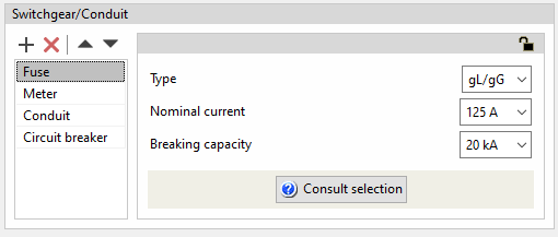
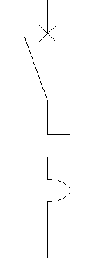
Fuse
Like the circuit breaker, fuses are generally used to protect the line against overcurrents and short circuits.
The program can be used to define fuses in a group, line or circuit by indicating the following characteristics:
- Type (gL/gG / aM)
- Nominal current (A)
- Breaking capacity (kA)
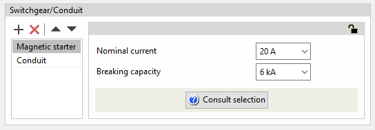
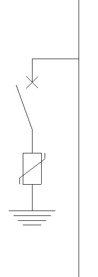
Magnetic starter
The magnetic starter is the element that is usually fitted for overcurrent and short-circuit protection on lines feeding motor loads.
The program can be used to define magnetic starters in a line or a circuit by specifying the following characteristics:
- Nominal current (A)
- Breaking capacity (kA)
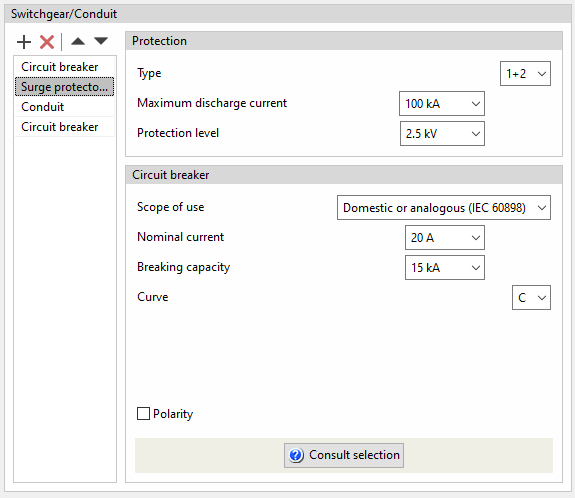
Surge protector for transient overvoltages
The program can be used to define surge protector for transient overvoltages (protection device for overvoltages of atmospheric origin) in a group, a line or a circuit by specifying the following characteristics:
- Protection
- Type (1+2 / 1 / 2 / 3)
- Maximum discharge current (kA)
- Protection level (kV)
- Circuit breaker
Used to define the circuit breaker associated with the transient overvoltage limiter, with the same options as when entering it independently.
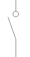
Sectionaliser
This option is used to add a disconnector at the group, line or circuit level. The program does not require any additional parameter definition.
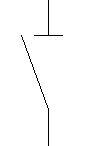
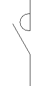
Switch disconnector
This option is used to add a switch disconnector to the line or circuit. The program does not require any additional parameter definition.
Contactor
This option is used to add a contactor to the group, line or circuit. The program does not require any additional parameters to be defined.
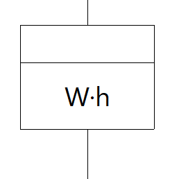
Meter
This option is used to add a meter to the line. The program does not require any additional parameter definition.
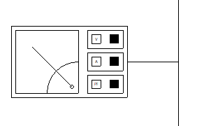
Network analyser
This option is used to add a network analyser to the group, line or circuit. The program does not require any additional parameters to be defined.
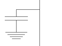
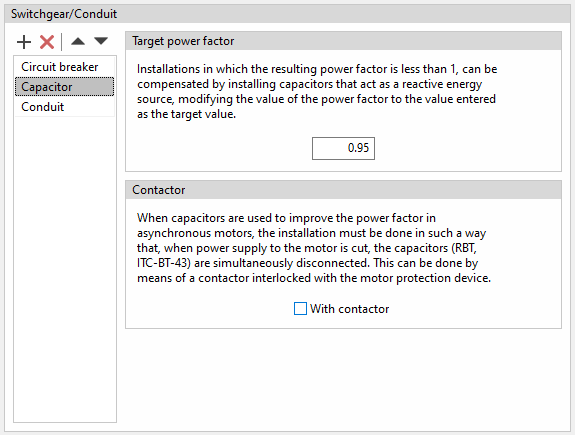
Capacitor
This option is used to add a capacitor in a circuit to compensate the power factor by specifying the following parameters:
- Target power factor
The capacitor acts as a source of reactive power which modifies the target power factor of the circuit. To do this, it allows a target power factor to be entered. This is useful in installations where the resulting power factor is less than 1. - Contactor
If capacitors are used to improve the power factor of asynchronous motors, the installation must be carried out in such a way that, when the power supply to the motor is cut off, the capacitors are simultaneously disconnected. This can be done by means of a contactor interlocked with the motor protection device. To indicate their existence in the program, the following option must be checked:- With contactor (optional)
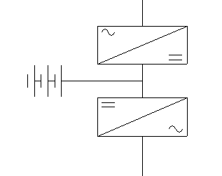
Battery
This option is used to add a battery to the line or circuit. The program does not require any additional parameter definition.
Conduit
This is an element that will always appear in the list and cannot be deleted. Its purpose is to remind the user of the need to establish the order of the switchgear elements depending on whether they are to be placed at the beginning or at the end of the line, to establish the reference installation methods and the characteristics of the conduit, for which it will be possible to select between pipe, protection channel or without conduit.
This option varies if, in the "Description" section of the line or circuit, an IEC cable or an ANSI cable has been selected as the conductor. In each case, the program can configure the conduit of the line or circuit by means of the following options:
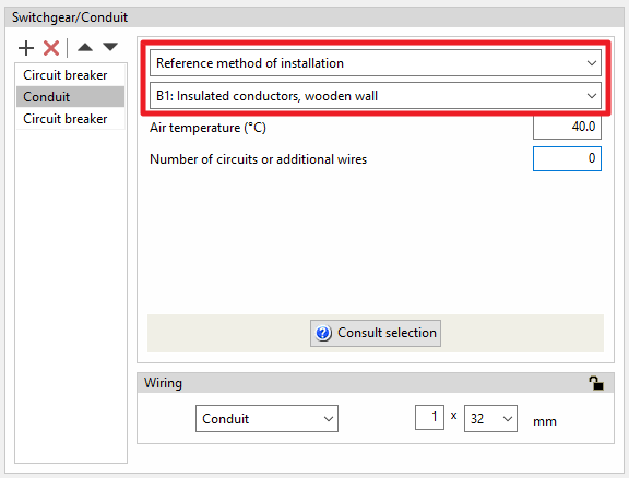
Conduit for IEC cables
- Defining the reference installation method
The definition of the reference installation method can be done directly, if available, or by using a data selection wizard:- Reference installation method
If this option is selected, the program allows users to specify the reference installation method directly.
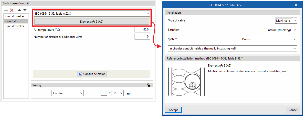
- IEC 60364-5-52, Table A.52.3
If this option is selected, the program launches a data selection wizard that allows users to indicate the characteristics of the conduit in detail through a series of drop-down menus, and then displays the corresponding reference installation method with these data according to the aforementioned table of the standard:- Installation
Indicates the conduit's characteristics:- Type of cable (Isolated / Single-core / Multi-core)
- Situation (Surface / Interior (fixed) / Building opening / Buried)
- System (Ducts / Cable trunking (including mouldings) / Directly fixed in masonry)
- Reference installation method (IEC 60364-5-52, Table A.52.3)
Displays the reference installation method (IEC 60364-5-52, Table A.52.3) corresponding to the selected data.
- Installation
- Reference installation method
The following information is also required in any of the cases mentioned above:
- Air temperature (ºC)
- Number of circuits or additional wires
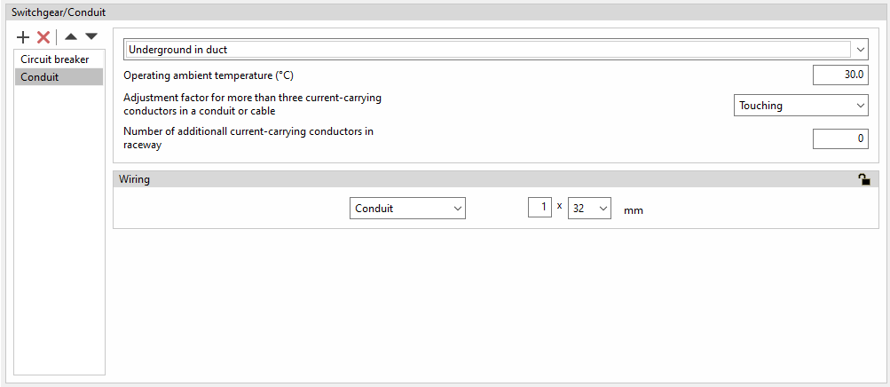
Conduit for ANSI cables
In this case, the program offers a choice between the following installation methods:
- Underground in duct / Underground directly buried / Aboveground in trays / Aboveground in conduits / Free air / Supported on a messenge
The following parameters are also defined:
- Operating ambient temperature (ºC)
- Adjustment factor for more than three current-carrying conductors in a conduit or cable
This parameter allows users to manually edit the number of current-carrying conductors in a single conduit in order to adjust the cable ampacity correction factor according to table 310.15(B)(3)(a) of the NEC (National Electrical Code) standard. This selection will be reflected later in the cable ampacity justification report. - Number of additional current-carrying conductors in raceway
Wiring
The wiring through which the conduit runs can be defined by choosing from the following options. More than one unit of protective pipe or duct can be inserted:
- Without duct
- Pipe (Number of pipes x Diameter)
- Protection channel (Number of protection channels x Width x Height)