Entering fittings into the water supply system and generating localised pressure drops at pipe joints
In “Installation” under the “Water Systems” tab in the “Water supply” group of the main toolbar, the following elements of the water supply system can be entered:

Fitting
Inserts fittings into the water supply system.
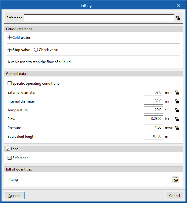
When entering or editing a fitting, the following parameters can be configured. Some parameters only appear if the "Simplified entry" option in "Design options" under "General options" is deactivated:
- Reference
Element reference. This value can be locked or unlocked. The program will create or modify the reference when updating results if unlocked. - Fitting reference
Selects the type of fitting by its reference and depending on whether it is located in a "Cold water", "Hot water", "Hot water return", "Auxiliary supply" or "Auxiliary return" pipe. These types can be created and edited from "Design and check options to be carried out" in "General options", in the "Project" group. - General data
The element's general data can be defined. Some of these values can be locked or unlocked. If a value is locked when updating the results, it is not modified and remains unchanged.- Specified operating conditions (optional) (Start of the installation / End of the installation)
- Diameter (Lock/Unlock)
Selects the technical characteristics of the pipe associated with the fitting. This option only appears if the “Material reference” option is activated in the type of fitting defined in "Design and check options to be carried out" in "General options", in the "Project" group. - External diameter / Internal diameter (Lock/Unlock)
These options only appear if the “Material reference” option is activated in the type of fitting defined in "Design and check options to be carried out" in "General options", in the "Project" group. - Temperature (Lock/Unlock)
- Flow (Lock/Unlock)
- Pressure (Lock/Unlock)
- Loss coefficient / Local pressure loss / Equivalent length
Defines the value of the loss coefficient, the local pressure loss or the equivalent length associated with the element. These options only appear if the “Material reference” option is activated in the type of fitting defined in "Design and check options to be carried out" in "General options", in the "Project" group.
- 3D layout
The position and angle of the element can be defined. This section only appears when editing a previously entered element.- Position (x, y, z)
- Angle
- Label (optional)
The information visible in the element's label can be managed.- Reference (optional)
- Bill of quantities
The element's bill of quantities generation can be controlled by filters.- Fitting
| Note: |
|---|
| The “Water supply” option in the bottom right corner of the group gives access to the options for defining the elements of this group. These options are equivalent to those available in "Design and check options to be carried out" in "General options", in the "Project" group. Fittings with a checked box will be available as additional quick-access options in this tool group. This allows users to enter the desired fittings quickly. |
Generating local pressure losses in pipe joints
The program includes two tools for the automatic generation of "Localised pressure drops in pipe joints":
- The first option generates pressure losses at the joints of all the pipes in the job.
- The second option generates the pressure losses at the pipe joints selected by the user.
After using any of these tools, the program reports the number of intersections where a localised pressure loss has been generated. From here, users can edit or delete the fittings created in the process if they wish to do so.
For these options to be available, the corresponding boxes must be activated in "Localised pressure drops in pipe joints" found in “Generation” under “Design options”, and in turn, under "General options". From here it is also possible to configure the type of fitting associated with each type of pipe joint.


