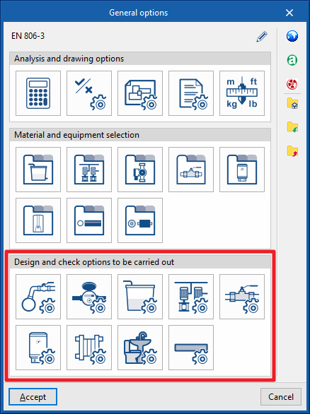
Setting the design and check options to be carried out on the water supply system
In the "Installation" tab of the "Water Systems" tab, in the "General options" of the "Project" group of the main toolbar, the "Design and check options to be carried out" can be defined for the following elements of the water supply system:

- Supply connection points
- Meters
- Tanks
- Pumping system
- Fitting
- Hot water production
- Heat exchangers
- Consumption
- Pipes
These criteria and option catalogues must be defined for each type of element before they are selected and entered into the model.
By using the "Import configuration" option, available on the right-hand side of the "General options" panel, this data can be automatically generated for different national and international standards. The data of different manufacturers can also be imported by clicking on the options displaying their logo.
The other options in the right-hand column allow the complete configuration of the "General options" panel to be imported and exported to files on disk, as well as selecting a file with initial values for creating a new job.
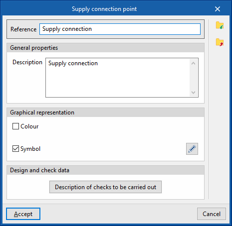
Supply connection point
Used to define the supply connection points available in the project. These elements are then entered in the model via the "Supply connection point" option in the "Water supply" group.
When defining a supply connection point, the following parameters must be specified:
- Reference
Supply connection point reference. - General properties
- Description
- Graphical representation
- Colour (optional)
- Symbol (optional)
- Design and check data
- Description of checks to be carried out
Used to enter a descriptive text of the checks to be carried out on the element. This text will appear in the reports next to each check.- Flow
- Pressure
- Description of checks to be carried out
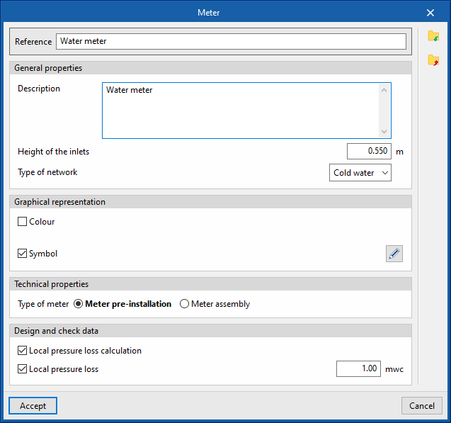
Meters
Used to define the meters available in the project. These elements are then entered in the model via the "Meter" option in the "Water supply" group.
When defining a meter, the following parameters must be specified:
- Reference
Meter reference. - General properties
- Description
- Height of the inlets
- Type of network (Cold water / Hot water)
- Graphical representation
- Colour (optional)
- Symbol (optional)
- Technical properties
- Type of meter
- Meter pre-installation
- Meter assembly
- Type of meter
- Design and check data
- Local pressure los calculation (optional)
Enters local pressure drop values for meters. - Local pressure loss (optional)
Defines a local pressure drop value associated with the meter type. If left deactivated, the local pressure drop must be defined for each particular element of the meter type.
- Local pressure los calculation (optional)
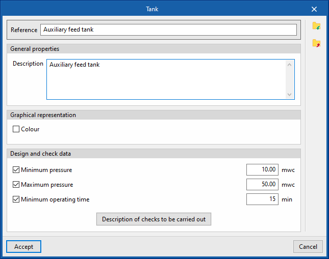
Tanks
Used to define the tanks available in the project. These elements are then entered in the model via the "Tank" option in the "Water supply" group.
When defining a tank, the following parameters must be specified:
- Reference
Tank reference. - General properties
- Description
- Graphical representation
- Colour (optional)
- Design and check data
- Minimum pressure (optional)
Minimum pressure required at the tank inlet. - Maximum pressure (optional)
Maximum pressure required at the tank inlet. - Minimum operating time (optional)
- Description of checks to be carried out
Used to enter a descriptive text of the checks to be carried out on the element. This text will appear in the reports next to each check.- Pressure
- Estimated operating time
- Minimum pressure (optional)
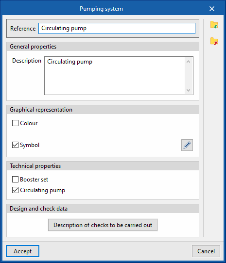
Pumping system
Used to define the pumping systems available in the project. These elements are then entered in the model via the "Pumping system" option in the "Water supply" group.
When defining a pumping, the following parameters must be specified:
- Reference
Pumping system reference. - General properties
- Description
- Graphical representation
- Colour (optional)
- Symbol (optional)
- Technical properties
Indicates whether the pumping system is a booster set or a circulation pump by activating the corresponding option.- Booster set (optional)
- Circulation pump (optional)
- Design and check data
- Description of checks to be carried out
Used to enter a descriptive text of the checks to be carried out on the element. This text will appear in the reports next to each check.- Pressure increase
- Description of checks to be carried out
Fittings
Used to define the fittings and manifolds available in the project. The subsequent entry of these elements in the model can be done through the "Fitting" and "Manifold" options or through the options for the automatic generation of localised pressure losses, in the "Water supply" group.
"Fittings" tab
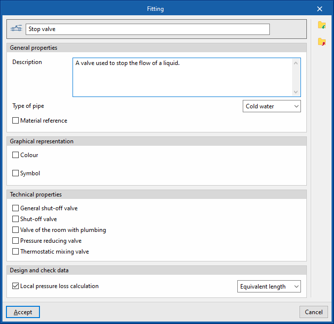
When defining a fitting, the following parameters must be specified:
- Reference
Fitting reference. The button on the left is used to change the associated "Icon" if this fitting is activated in the tool group. - General properties
- Description
- Type of pipe (Cold water / Hot water / Hot water return / Auxiliary supply / Auxiliary return)
- Material reference
Used to select one of the materials entered in the "Fittings" table, in the "Material and equipment selection" section of the "General options".
- Graphical representation
- Colour (optional)
- Symbol (optional)
- Technical properties
Indicates the type of fitting by checking the corresponding option from those available:- General shut-off valve (optional)
- Shut-off valve (optional)
- Valve of the room with plumbing (optional)
- Pressure reducing valve (optional)
- Thermostatic mixing valve (optional)
- Design and check data
- Local pressure loss calculation (optional)
Activates the calculation of localised pressure loss in the fitting and defines the calculation criterion by selecting it from those available:- Loss coefficient
- Local pressure loss
- Equivalent length
- Local pressure loss calculation (optional)
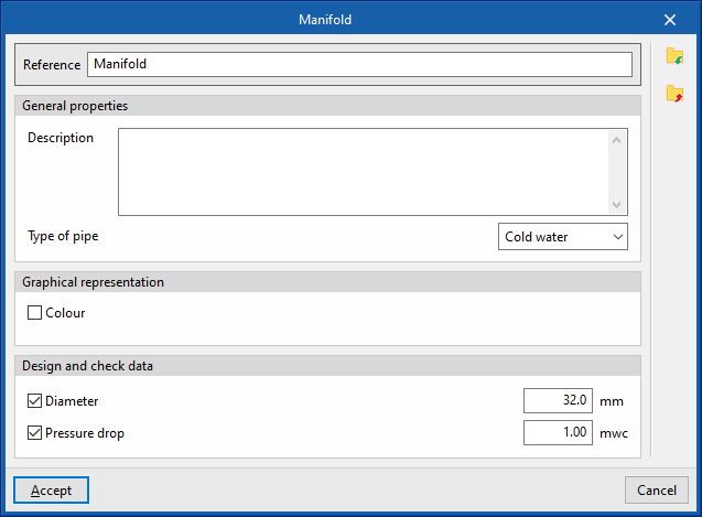
“Manifold” tab
When defining a manifold, the following parameters must be specified:
- Reference
Manifold reference. - General properties
- Description
- Type of pipe (Cold water / Hot water / Hot water return / Auxiliary supply / Auxiliary return)
- Graphical representation
- Colour (optional)
- Design and check data
- Diameter (optional)
Allows the diameter associated with the manifold to be defined. If this option is deactivated, the program requires this value to be entered for each element in the model. - Pressure drop (optional)
Defines the pressure loss associated with the manifold. If this option is deactivated, the program requires this value to be entered for each element in the model.
- Diameter (optional)
Hot water production
Used to define the hot water production systems available in the project. The subsequent entry of these elements in the model can be carried out by means of the "Hot water production" option, in the "Hot water" group.
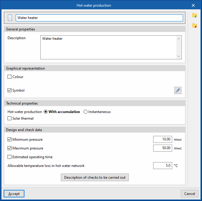
When defining a hot water production system, the following parameters must be specified:
- Reference
Hot water production system reference. The button on the left changes the associated "Icon" if this system is activated in the tool group. - General properties
- Description
- Graphical representation
- Colour (optional)
- Symbol (optional)
- Technical properties
Specifies the technical characteristics of the hot water production system:- Hot water production (With accumulation / Instantaneous)
- Solar thermal
- Design and check data
- Minimum pressure (optional)
Minimum pressure required at the inlet of the hot water production system. - Maximum pressure (optional)
Maximum pressure required at the inlet of the hot water production system. - Estimated operating time (optional)
- Allowable temperature loss in hot water network
- Description of checks to be carried out
Used to enter a descriptive text of the checks to be carried out on the element. This text will appear in the reports next to each check.- Flow
- Pressure
- Estimated operating time
- Minimum pressure (optional)
Heat exchangers
Used to define the heat exchangers available in the project. These elements are then entered in the model via the "Heat exchanger" option in the "Water supply" group.
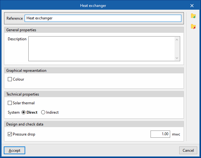
When defining a heat exchanger, the following parameters must be specified:
- Reference
Heat exchanger reference. - General properties
- Description
- Graphical representation
- Colour (optional)
- Technical properties
Specifies the technical properties of the heat exchanger:- Solar thermal (optional)
- System (Direct / Indirect)
- Design and check data
- Pressure loss (optional)
Defines a pressure loss value associated with the type of heat exchanger.
- Pressure loss (optional)
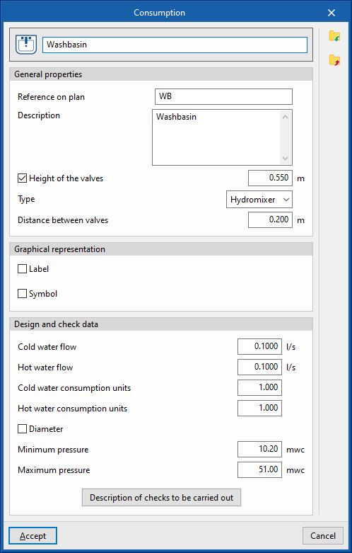
Consumption
Defines the consumptions available in the project. The subsequent entry of these elements in the model can be carried out by means of the "Consumption" option in the "Consumption" group.
When defining a consumption, the following parameters must be specified:
- Reference
Consumption reference. The button on the left can be used to change the associated "Icon" if this consumption is activated in the tool group. - General properties
- Reference on plan
- Description
- Height of the valves (optional)
- Type (Hydromixer / Cold water / Hot water)
- Distance between valves
- Graphical representation
- Label (optional)
- Reference (optional)
- Symbol (optional)
- Label (optional)
- Design and check data
- Cold water flow / Hot water flow (in “Hydromixer” consumption)
Cold and hot water flow rates required by consumption. - Flow (in “Cold water” or “Hot water” types of consumption)
Cold water flow rate or hot water flow rate required by consumption. - Diameter (optional)
- Minimum pressure
Minimum pressure required for consumption. - Maximum pressure
Maximum pressure required for consumption. - Description of checks to be carried out
Used to enter a descriptive text of the checks to be carried out on the element. This text will appear in the reports next to each check.- Pressure
- Cold water flow / Hot water flow (in “Hydromixer” consumption)
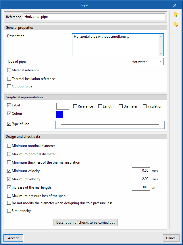
Pipes
Used to define the pipes available in the project. The subsequent entry of these elements into the model is carried out by means of the options available in the "Pipes" group.
When defining a pipe, the following parameters must be specified:
- Reference
Pipe reference. - General properties
- Description
- Type of pipe (Cold water / Hot water / Hot water return / Auxiliary supply / Auxiliary return)
- Material reference
Used to select one of the materials entered in the "Pipe catalogue" table, in the "Material and equipment selection" section of the "General options". - Thermal insulation reference
Used to select one of the materials entered in the "Thermal insulation catalogue" table, in the "Material and equipment selection" section of the "General options". - Outdoor pipe (optional)
Indicates that the pipe is located outdoors.
- Graphical representation
- Label (optional)
- Reference (optional)
- Length (optional)
- Diameter (optional)
- Insulation (optional)
- Symbol (optional)
- Colour (optional)
- Type of line (optional)
- Label (optional)
- Design and check data
- Minimum nominal diameter (optional)
Minimum allowable nominal diameter of the pipe. - Maximum nominal diameter (optional)
Minimum allowable nominal diameter of the pipe. - Minimum thickness of the thermal insulation (optional)
Minimum required thickness of thermal insulation. - Minimum velocity (optional)
Minimum permissible velocity of the fluid in the span. - Maximum velocity (optional)
Maximum permissible velocity of the fluid in the span. - Increase of the real length (optional)
Considers a percentage increase of the actual pipe length over the length entered in the model. - Maximum pressure loss of the span (optional)
Maximum allowable pressure loss of the pipe span. - Do not modify the diameter when designing due to a pressure loss (optional)
- Simultaneity (optional)
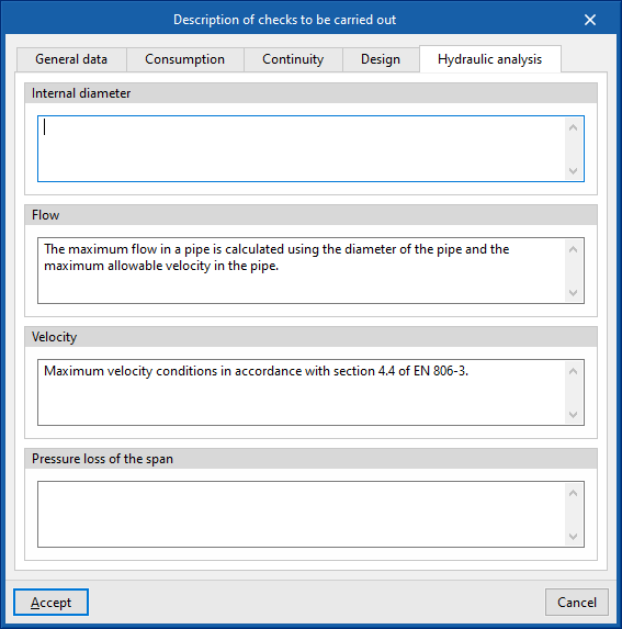
Selects one of the simultaneity design methods entered under "Simultaneity" in the "Design options" section of the "General options". - Description of checks to be carried out
Used to enter a descriptive text of the checks to be carried out on the element. This text will appear in the reports next to each check.- "General data" tab
- Internal diameter
- "Consumption" tab
- Internal diameter
- "Continuity" tab
- Diámetro nominal
- "Design" tab
- Internal diameter
- "Hydraulic" tab
- Internal diameter
- Flow
- Velocity
- Pressure loss of the span
- "General data" tab
- Minimum nominal diameter (optional)