Tools in the "Floor plans" tab
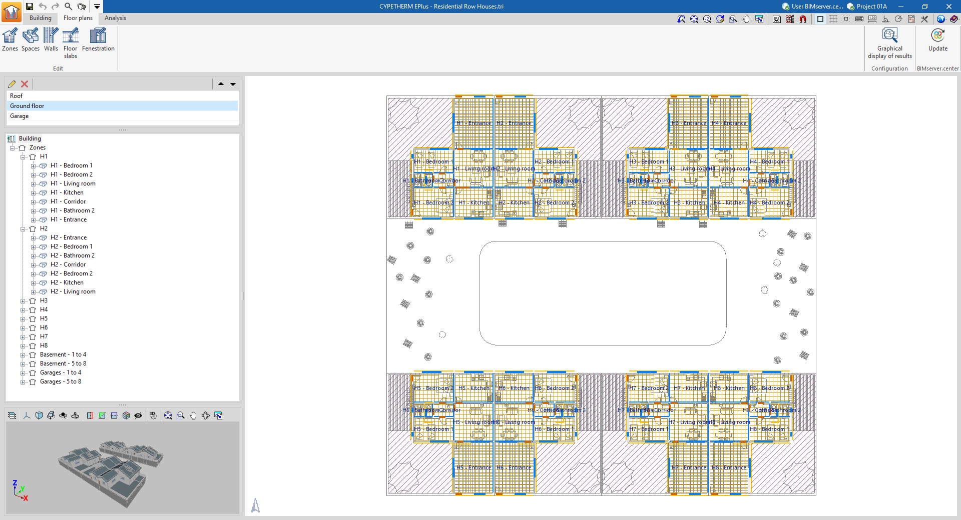
The "Floor plans" tab contains the floor plans of each floor of the building, where the building elements are represented.
From this view, the characteristics of the building's construction elements can be viewed and edited by first selecting the corresponding button on the toolbar and then selecting the specific element on the floor plan in the main window. When an element is selected in the tree diagram, it will be highlighted in the 3D viewer and in the floor plan.
Floor plans are automatically generated from the BIM model. Templates in DXF/DWG format can also be imported and viewed from the BIM model using the "DXF-DWG Templates" button on the top toolbar.
"Floor plans" tab interface
This tab has an interface with the following areas:

- Floor plan selector
In this area, located by default at the top of the left-hand side, the floor plan to be represented in the work area can be selected.
- Building tree
This area, located at the bottom of the left-hand side, offers a navigation tree where the elements that make up the building can be selected. In the work area, the program highlights the elements of the model associated with the level selected in the tree.
- 3D view
This area, located at the bottom of the left-hand side, illuminates in orange the elements of the model associated with the level selected in the tree.
- Work area
The work area, in the centre of the interface, is a view where the selected floor plan is displayed. The elements are coloured according to their type.
Options in the top toolbar of the "Floor plans" tab
The following tools are available in the top toolbar:
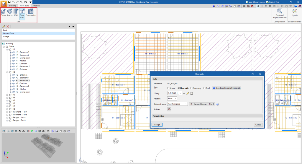
"Edit" group
Selects and edits "Zones", "Spaces", "Walls", "Floor slabs" or "Openings" on the floor plan.
Clicking on each element in the work area opens an editing window where its properties can be consulted or modified.
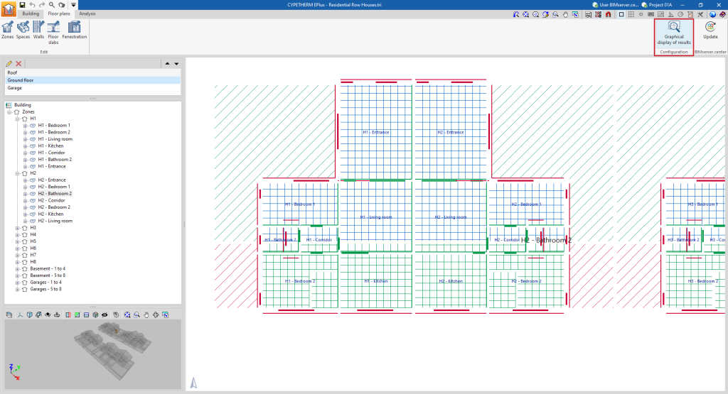
"Configuration" group
This enables a "Graphical display of results" to be carried out, so that the elements of the model are represented using the following colour code, depending on whether or not they belong to the thermal envelope:
- Elements belonging to the external thermal envelope shall be shown in red (e.g. façade envelope, roof or floor screed of a living space).
- Elements belonging to the internal thermal envelope shall be shown in blue (e.g. a floor slab or a partition wall between the living room of a dwelling and a garage that constitutes an area not included in the thermal envelope).
- Elements that do not belong to the thermal envelope (either internal partitions or elements excluded from the analysis) shall be shown in green (e.g. an internal partition wall between two rooms of the same thermal zone).


