Managing the libraries of openings
The characteristics of the openings must be defined in the project libraries to detail the data related to their thermal behaviour. This data can be entered manually or based on different catalogues and reference standards with predefined materials and will affect the energy simulation carried out by the program.
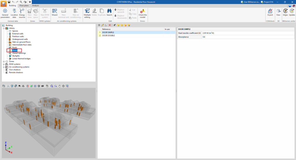
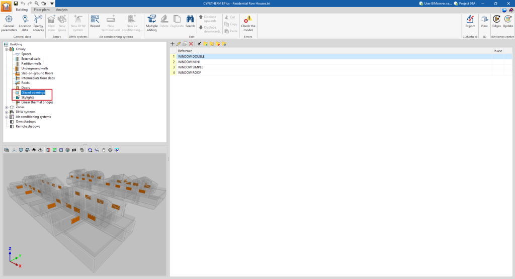
The tools for managing the libraries of openings in the model can be found in the "Building" tab and, within the outline of the left-hand side area of the "Project" definition, in the "Library" tree, then selecting the corresponding level.
Categories of openings
The openings in the building are classified into the following categories within the library:
- Doors. These are entirely opaque openings.
- Glazed openings. These are translucent openings in vertical enclosures, such as glazed windows and doors.
- Skylights. These are translucent openings in horizontal envelopes.
It is also possible to define glazed envelopes with the following option, which behave similarly to glazed openings:
- Envelopes ("Glazing" option). These are vertical translucent envelopes in contact with the external environment, such as curtain wall façades.
Defining doors
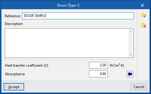
The following parameters must be defined for the types of doors:
- Reference
- Description
- Heat transfer coefficient (U)
Heat transfer coefficient of the door. - Absorptance
The absorbance coefficient fluctuates between 0 and 1. The value can be imported with the wizard available on the right:
Import absorptance
The value of this coefficient is lower on light surfaces, and higher on dark surfaces.
Defining glazed openings and skylights
The following parameters must be defined for glazed openings and skylights:
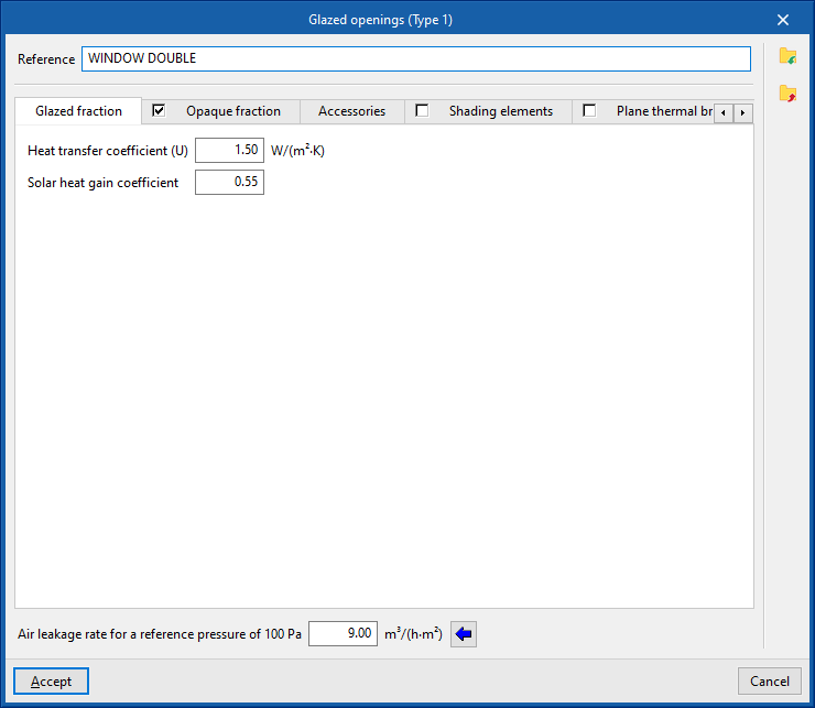
- Air leakage rate for a reference pressure of 100 Pa. This value is used for calculating infiltration and is given by the class of the window. Usual values can be imported using the wizard on the right.
The rest of the opening parameters are defined in the following tabs:
"Glazed fraction" tab
Specifies the heat transmission coefficient (U-value) and the solar factor of the opening. If the "Opaque fraction" tab is activated, the values indicated in this panel apply only to the glazed fraction of the opening. Otherwise, they will affect the complete geometry of the opening.
- Connection with Open BIM Database
Logs into the Open BIM Database. - Importing manufacturer data
Imports glazing data from one of the available manufacturers by selecting the catalogue and the desired product. - Heat transfer coefficient (U)
Heat transfer of the glazing fraction. - Solar factor
- Solar factor of the glazing or the proportion of solar radiation that the glazing allows to pass through, in percent. The lower the solar factor, the less solar radiation enters the interior.
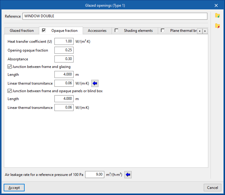
"Opaque fraction" tab (optional)
Specifies the opaque fraction or frame fraction of the opening and its thermal properties, as well as the existence of thermal bridges due to the coupling between the different parts forming the opening, which are defined by their length and their linear thermal transmittance.
- Heat transfer coefficient (U)
Heat transfer coefficient of the opaque fraction. - Opening opaque fraction
Proportion of the opening in percent occupied by the opaque part (frame or joinery). - Absorptance
Absorption coefficient of the radiation incident on the frame. - Junction between frame and glazing (optional)
Activating this box declares the existence of thermal bridges due to the coupling between the frame and the glazing.- Length
Length of thermal bridges between the glazing and the frame. - Linear thermal transmitance
Linear thermal transmittance of thermal bridges between frame and glazing. A wizard for determining this parameter with values from EN ISO 10077-1 is provided on the right-hand side.
- Length
- Junction between frame and opaque panels or blind box (opcional)
Activating this box declares the existence of thermal bridges due to the junction between the frame and the opaque panels or the blind box.- Length
Length of thermal bridges between the frame and the opaque panels or the blind box. - Linear thermal transmittance
Linear thermal transmittance of thermal bridges between the frame and the opaque panels or the blind box.
- Length
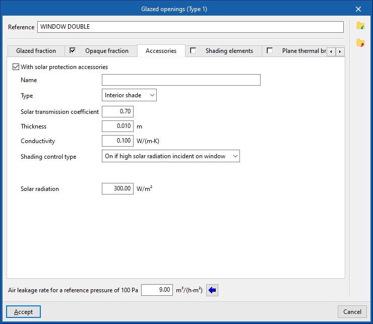
"Accessories" tab
Adds solar shading accessories, either external (blinds) or internal (curtains), and defines their activation.
- With solar protection accessories (optional)
- Name
- Type (Interior shade / External shade)
- Solar transmission coefficient
Proportion of solar radiation that the accessory allows to pass through, in per cent. - Thickness
- Conductivity
- Shading control type
- Always on
Considers that the defined shading is always on at all times of the year. - Always off
Considers that the defined shading is always off. - On if schedule allows
Creates and edits an hourly, daily, weekly or monthly schedule that details the times when shading is active or inactive.- Schedule
- On if high solar radiation incident on window
Defines a maximum solar radiation value, above which the shading is considered to be active.- Solar radiation
- Always on
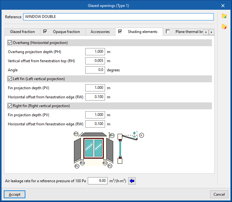
"Shading elements" tab
Shading elements are used to simulate the effect of façade projections such as outside reveal depth, overhangs over the window or lateral projections that produce shading on the opening, if they have not been defined in the geometric model and included or inserted in the tree of building elements.
- Overhang (Horizontal projection) (optional)
- Overhang projection depth (PH)
- Vertical offset from fenestration top (RH)
- Angle
- Left fin (Left vertical projection) (optional)
- Fin projection depth (PV)
- Horizontal offset from fenestration edge (RW)
- Lateral derecho (proyección vertical) (opcional)
- Fin projection depth (PV)
- Horizontal offset from fenestration edge (RW)
The program displays a generic diagram at the bottom of the screen with the layout of the opening and possible shading elements to help in defining its parameters.
The options for defining shading elements in glazed openings and skylights allow users to enter this data specifically if it cannot be obtained from these other sources of information.
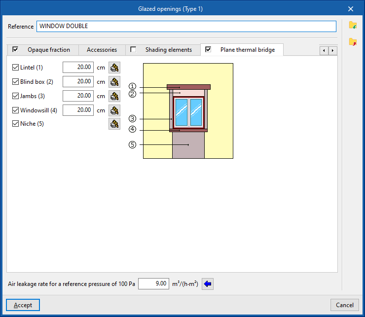
"Plane thermal bridges" tab
Plane thermal bridges are used to define the building elements that make up the flat surfaces surrounding the opening if their characterisation differs from the building element where the opening is located and in order to take into account the heat transmission through them.
The plane thermal bridges available are as follows:
- Lintel (optional)
- Blind box (optional)
- Jambs (optional)
- Windowsill (optional)
- Niche (optional)
The program shows a generic diagram on the right-hand side with the representation of the opening and the possible plane thermal bridges, which helps to understand their layout.
In each of them, the value of the width must be defined. This width, together with other data such as the width or height of the opening, will provide the area of the plane thermal bridge. In the case of niches, the plane thermal bridge extends from the floor to the opening.
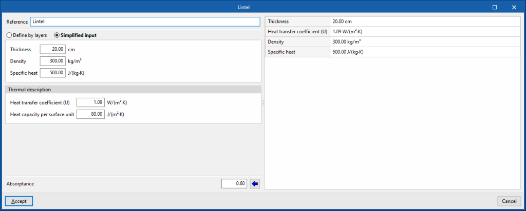
By editing each plane thermal bridge, the characteristics can be defined by material layers or in a simplified form via their overall thermal properties, just like the opaque building elements:
- Reference
- Define by layers / Simplified input
- Absorptance