Editing spaces in the building tree diagram
Within each zone, the spaces that make up the zone are defined. The building spaces and their building elements are imported from the BIM model, so the parameters that appear in this section will be obtained automatically.
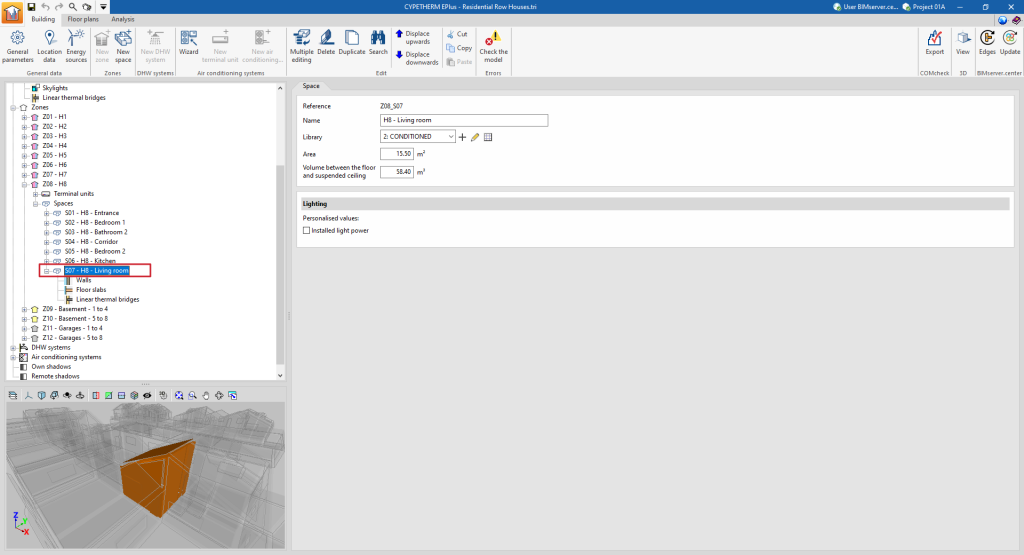
When any space is selected in the tree diagram in the left-hand side panel of the "Building" tab, it is highlighted in the 3D model viewer and the "Space" panel, where the properties of the space are defined, is displayed in the main area.
"Space" panel
A space is defined by its associated type, among those available within the library, and its general geometrical characteristics, such as area and volume:
- Reference
The numbered reference of the space is automatic and depends on its position in the diagram.
- Name
Name of the space. This parameter can be edited directly.
- Library
Selection of the space type from the drop-down menu from those available in the "Library". The program can create, edit or directly manage the libraries of space types with the options to the right of the drop-down menu.
- Area
Area of the space. This value is used to compute the simulation results per unit area. Spaces without a floor slab area ("Area" equal to 0) can be defined, provided that at least one space in the same thermal zone has an "Area" value greater than 0.
- Volume between the floor and suspended ceiling
Volume of the space. The space between the floor and the suspended ceiling.
- "Illumination" section
An individualised value of installed lighting power can be defined for each space. If this option is checked, the defined value will replace the value of the corresponding library type. This option will only be available if the space type chosen in "Library" has a lighting load defined ("Lighting" checkbox activated). This data can be imported from the BIM model information.- Installed light power (optional)
In the diagram of the building, within each space, the building elements that compose it and the thermal bridges associated with the space are visualised and defined.
Building components in the space: walls and floor slabs
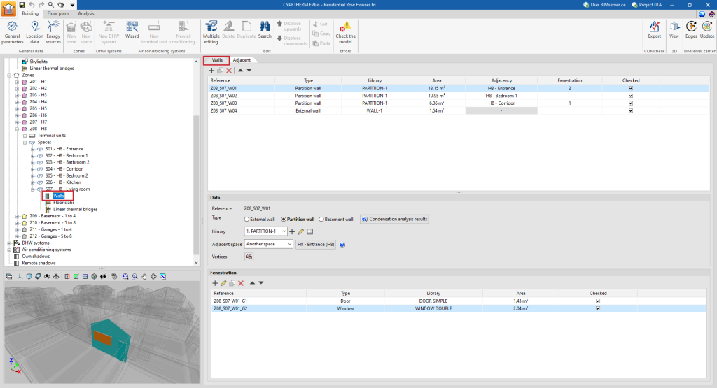
The building elements of the space are divided into two groups: "Walls" (vertical elements) and "Floor slabs" (horizontal elements). By selecting each of these groups, the main area on the right side of the interface is displayed:
- in the first tab (with the "Wall" or "Floor slabs" name), a table with the report with the list of concrete elements that make up the space;
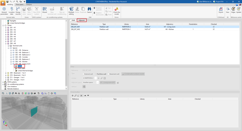
- and in the second tab ("Adjacent"), a table with a list of the adjacent elements.
These tables show different columns with information on the "Reference", the "Type" of the element, the type selected in the "Library", the "Area" of the element, the "Adjacency" or adjoining space, the number of "Fenestrations" and whether it is "Checked" or not.
When selecting a particular element from the report, it is highlighted in the 3D model viewer.
Elements that belong to two spaces at the same time, such as interior partitions, must not be defined twice, but will only be defined in one of the spaces, and indicated as being adjacent to the other. In the "Adjacent" tab, the properties of these elements can be viewed and the space to which they have been assigned can be consulted.
Data
Each building element is defined by the following characteristics, which are displayed at the bottom of the main viewing and editing area:
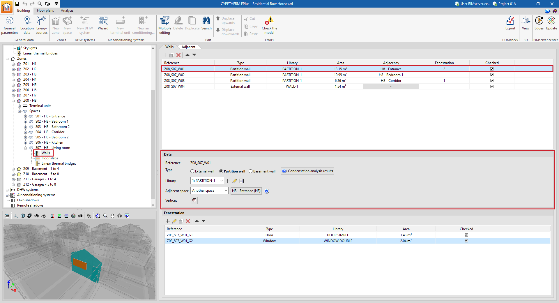
- Reference
The numbered element reference is automatic and depends on its position in the table. - Type
Defines the element type, which sets the conditions on the other side of the element (boundary conditions):- For walls:
- External wall
The conditions of the external environment are considered, with the following clarifications:- If the external wall has been defined as a party wall when editing its type in the library, the temperature conditions of the external environment are considered, with no exposure to the sun or wind (zone boundary wall).
- If the external wall has been defined as an adiabatic partition wall when editing its type in the library, adiabatic conditions are considered, i.e. there is no heat transfer through this element.
- Partition wall
The "Adjoining space" must be defined in the next point. - Basement wall
The conditions of the ground are considered. - For floor slabs:
- Screed
The conditions of the ground are considered. - Floor slab
The "Adjoining space" must be defined in the next point. - Roof
The conditions of the external environment are considered. - Overhang
The conditions of the external environment are considered.
- Screed
- External wall
- For walls:
- Condensation analysis results
Displays the results of the check for the existence of condensation on the element in case this calculation has been activated, according to the chosen "Type". - Library
The element type is selected from those available in the library, according to the "Type" chosen. The program offers the possibility to create, edit or manage directly the element type libraries with the options on the right of the drop-down menu. - Position (in "Floor slab" type elements)
Indicates whether the element is located on the floor or ceiling of the space. - Adjacent space (in "Partition" or "Floor slab" type elements)
For partition and floor slab type elements, the "Adjacent space" must be defined, according to the options offered in the drop-down menu:- Adiabatic element
Element between spaces with the same temperature conditions, so there is no heat transfer through it. - Another space
Selects the adjacent space from the spaces defined in the job. - Unknown space
The adjacent space is not defined on the job. The temperature conditions of this unknown space are assumed to be those of the outside air.
- Adiabatic element
- Total surface area of the screed / Total perimeter of the screed (in "Screed" type elements)
- Vertices
- Displays and defines the "x", "y" and "z" global coordinate points which determine the position and surface of the element.
Fenestration
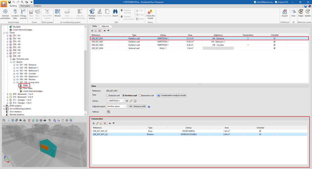
In opaque elements in contact with the exterior (envelopes, roofs, overhangs) and in interior partitions (partitions, floor slabs), openings can be defined in the table at the bottom of the interface. Openings are associated with the opaque elements that contain them, and are defined by the following characteristics:
- Reference
The numbered reference of an opening is automatic and depends on its position in the table. - Type
- For openings in "Walls" (external walls, partitions)
There is a choice between "Door", "Window" or "Opening". - For openings in "Floor slabs" (roofs, overhangs, floor slabs)
There is a choice between "Sky light" or "Opening". The openings represent an opening directly on the element and do not require the selection of a defined type in the library.
- For openings in "Walls" (external walls, partitions)
- Library
The type of element in the library is selected, according to the "Type" chosen. The program can be used to create, edit or directly manage opening type libraries with the options on the right-hand side of the drop-down menu. - Vertices
Used to display and define the global coordinate points that determine the position and surface of the opening. - Linear thermal bridges
Assigns linear thermal bridges (at the "Lower", "Upper" and "Sides" boundary) associated with the intersection of the opening with the envelope containing it.
The table of openings shows different columns with information about the "Reference", the "Type" of opening, the type selected in the "Library", the "Area" of the element and whether it is "Checked" or not.
Linear thermal bridges in the space
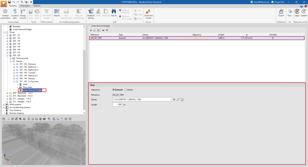
When selecting the "Linear thermal bridges" section within a space, the linear thermal bridges associated with the space are displayed in the main window.
This table shows different columns with information on the "Reference", the "Type" of linear thermal bridge, the type selected in the "Library", the "Adjacent" or adjoining space, the "Length" of the bridge, its linear thermal transmittance ("ψ") and whether it is "Checked" or not.
Each specific thermal bridge is defined by the environment that surrounds it (exterior or interior), its type of library and its length:
- Adjacency (Exterior / Interior)
The confinement environment of the linear thermal bridge is selected. - Reference
The numbered reference of the linear thermal bridge is automatic and depends on its position in the table. - Library
The type of linear thermal bridge is selected in the library. The program offers the possibility to create, edit or manage directly the libraries of linear thermal bridge types with the options on the right-hand side of the drop-down menu. - Length
Length of the linear thermal bridge. - With adjoining space (optional)
Selects the adjoining space in interior linear thermal bridges.


