Defining shading diagrams
Shading diagrams define the shadows cast on external elements of the thermal model such as façades, curtain walls, overhangs and roofs, as well as external doors, windows and skylights.
These diagrams are generated automatically in the usual workflows, either by modelling the building and neighbouring buildings and other obstacles in the "3D Model" tab, or by linking the job to a BIMserver.center project and importing BIM models with the geometry of the building and neighbouring buildings and other obstacles.
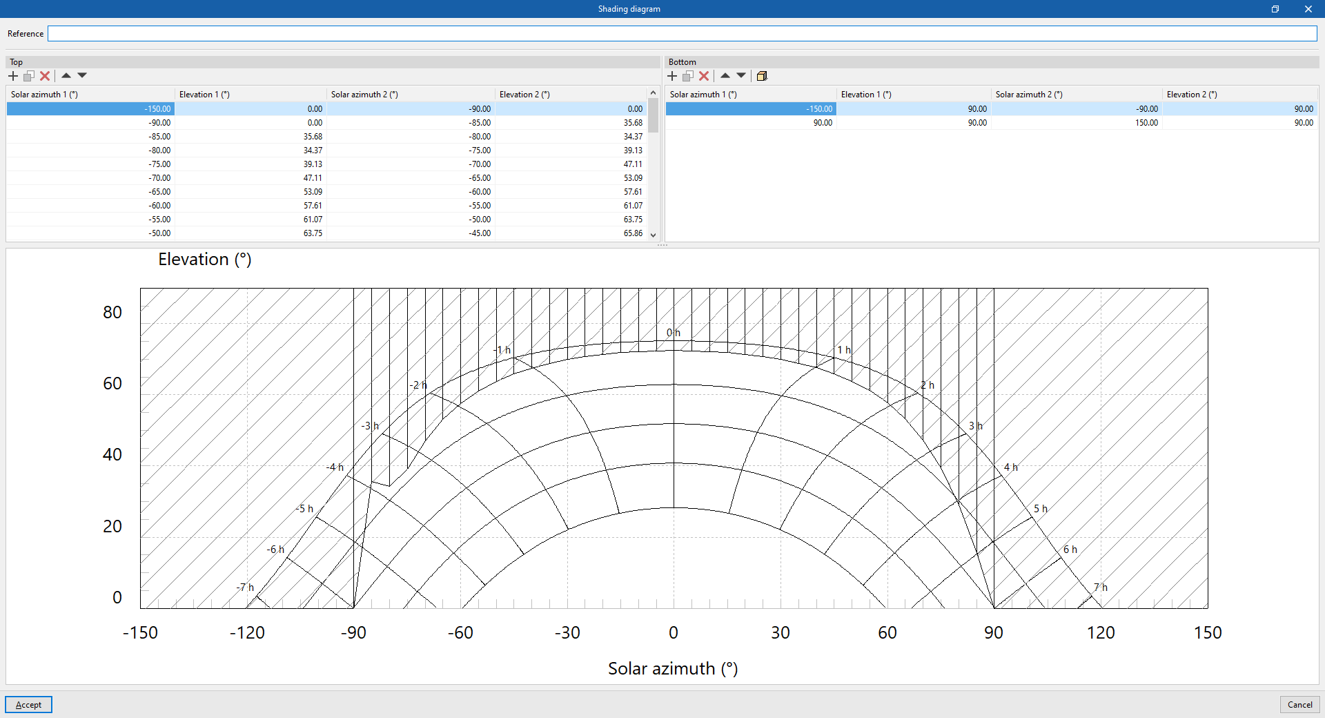
However, these diagrams can be consulted and edited by selecting the corresponding elements in the project tree of the "Thermal model" tab and then selecting "Detailed definition" in the drop-down menu of the "Shading" section. In the window for editing the shading profiles, the program allows the following data to be modified:

- Reference
Shading diagram reference.
Then, in the shadow diagram definition tables, users can consult the generated shadow polygons, enter them manually from their coordinates or generate them using the simplified option:
- Top
Manages the shadow polygons aligned with the upper elevation (90º). Each shadow polygon is a quadrilateral defined by four points with the following coordinates: (Solar Azimuth 1, 90º), (Solar Azimuth 1, Elevation 1), (Solar Azimuth 2, Elevation 2) and (Solar Azimuth 2, 90º). These shadow polygons can be used to define the shadows cast by cantilevers above the element.- Solar azimuth 1 (º)
This value must be between -180º and 180º. - Elevation 1 (º)
This value must be between 0º and 90º. - Solar azimuth 2 (º)
This value must be between -180º and 180º. - Elevation 2 (º)
This value must be between 0º and 90º.
- Solar azimuth 1 (º)
- Bottom
Manages the shadow polygons aligned with the bottom elevation (0º) or horizon. Each shadow polygon is a quadrilateral defined by four points with the following coordinates: Solar Azimuth 1, 0º; Solar Azimuth 1, Elevation 1; Solar Azimuth 2, Elevation 2; and Solar Azimuth 2, 0º. These shadow polygons can be used to define shadows cast by buildings or obstacles in front of the element.- Solar azimuth 1 (º)
This value must be between -180º and 180º. - Elevation 1 (º)
This value must be between 0º and 90º. - Solar azimuth 2 (º)
This value must be between -180º and 180º. - Elevation 2 (º)
EThis value must be between 0º and 90º.
- Solar azimuth 1 (º)
Finally, at the bottom, a solar chart is shown, indicating the position of the sun in the sky throughout the year, described by its height or elevation (or angle to the horizon) and its azimuth (angle to the south). The dashed portion shows the arrangement of the defined shadow polygons.
Create a polygon using the simplified option
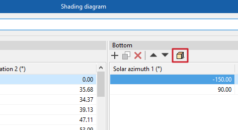
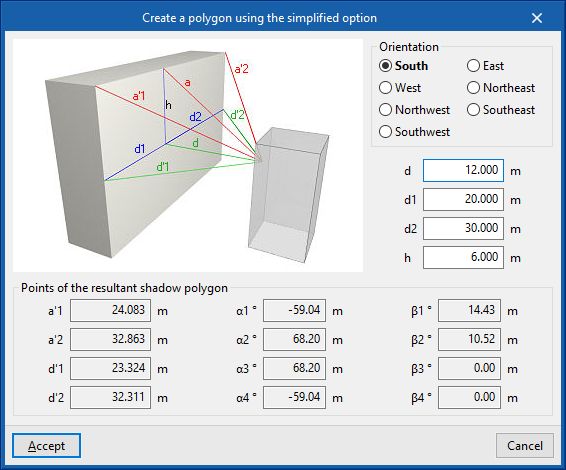
This option, available in the toolbar of the "Bottom" table, allows shadow polygons to be generated automatically by entering the following parameters, which indicate the geometry of the building or nearby obstacle and its position with respect to the element in a simplified form. Furthermore, a help scheme for the definition of these parameters is shown.
- Orientation (South / East / West / Northeast / Northwest / Southeast / Southwest / Southwest)
Orientation of the element where the shading diagram is being defined. - d
Distance from the element to the next building or obstacle. - d1
Length to the left of the next building or obstacle. - d2
Length to the right of the next building or obstacle. - h
Excess height of the building or nearby obstacle, with respect to the height of the centre of the element. - Points of the resulting shadow polygon (a'1, a'2, d'1, d'2, α1, α2, α3, α4, β1, β2, β3, β4)
These points and angles are automatically calculated when entering the other parameters in the wizard.
After accepting, the program generates the corresponding shadow polygons.


