Work environment in a "Thermal loads" project
If the "Thermal loads" project type has been selected, the program interface displays three tabs at the bottom of the main window, each with a different work environment: "3D model", "Thermal model" and "Thermal loads".
"3D Model" tab
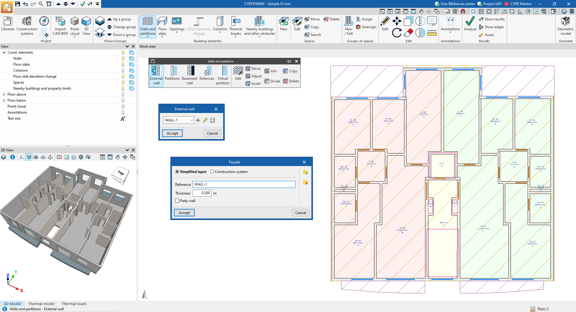
The "3D Model" tab appears if a BIM model has not been imported and contains tools that let you design the building’s geometric or architectural model directly within CYPETHERM. You can also define construction systems.
Further information on the tools in the "3D Model" tab can be found via the following link:
"Thermal model" tab
The "Thermal model" tab contains the tools that let you adjust and complete the description of the building model, incorporating the thermal properties of its components.
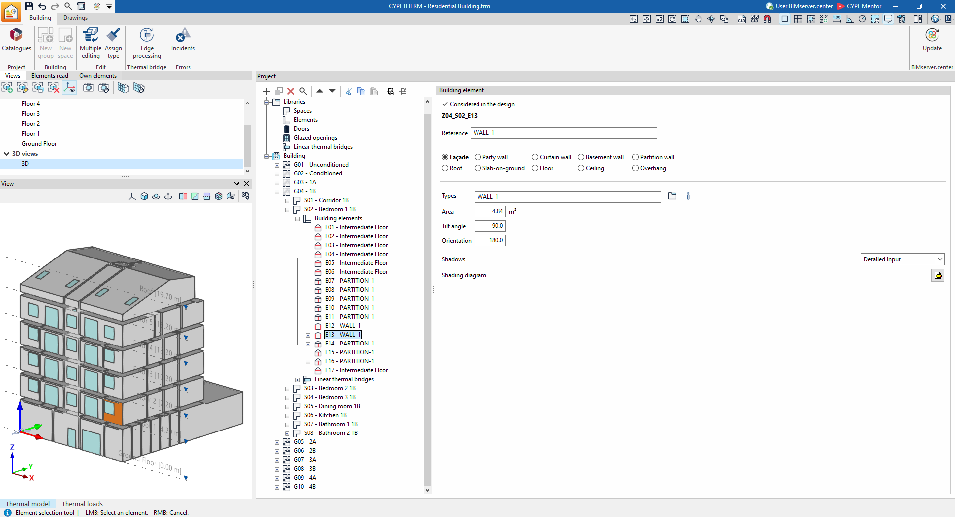
This tab is, in turn, organised into two further tabs at the top of the main window: "Building" and "Drawings":
"Building" tab
The "Building" tab is used to define the spaces, building elements, openings and linear thermal bridges that make up the building’s thermal model.
Further information on the model definition process can be found under the "Building" tab via the following link:
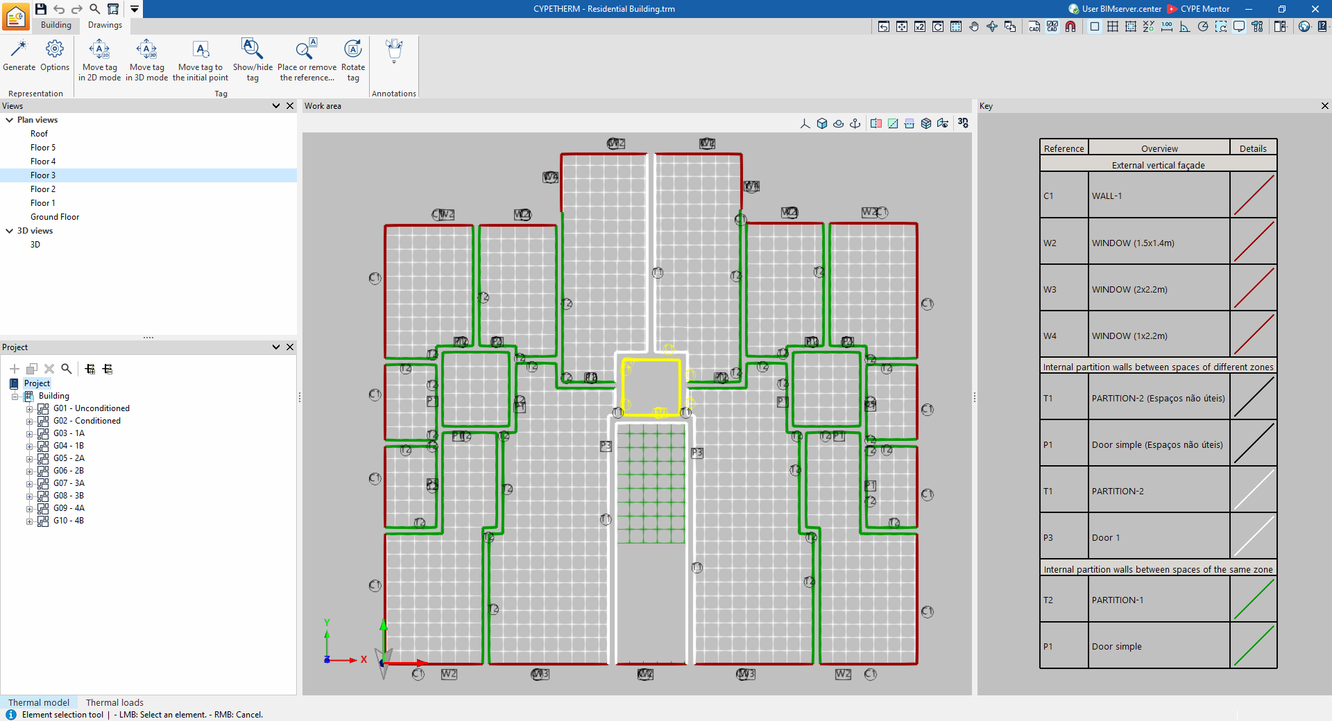
"Drawings" tab
The "Drawings" tab lets you create and edit the drawings for the building’s thermal envelope.
Further information on the options available on the "Drawings" tab can be found at the following link:
"Thermal loads" tab
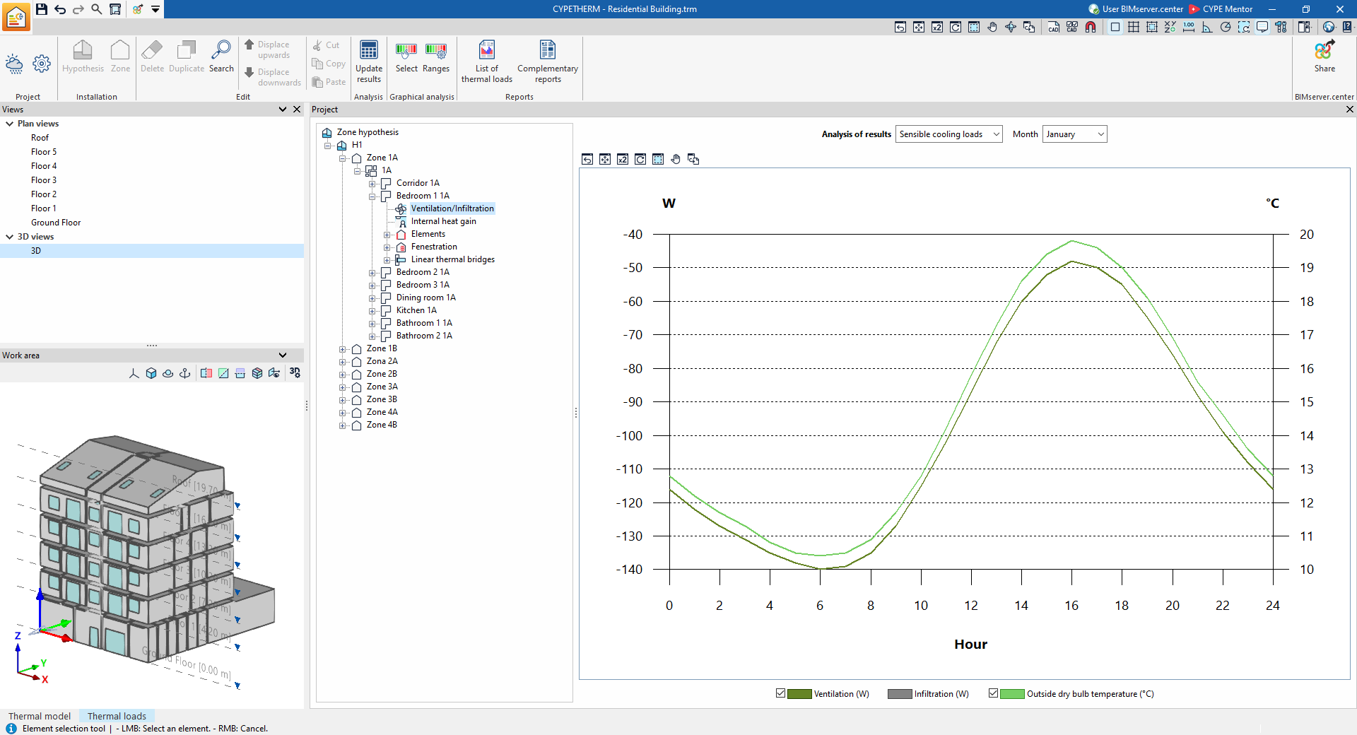
The "Thermal loads" tab contains the tools for calculating thermal loads and viewing the results in various reports and graphs.
Further information on the calculation and display of results can be found under the "Thermal loads" tab at the following link: