
Reinforced concrete block walls
With the "Reinforced concrete block walls" module, CYPECAD analyses and designs masonry walls made of concrete blocks.
These are vertical elements of any cross-section, made up of rectangles between each storey, defined by an initial and final level. The dimensions of each side can be different for each floor, and their thickness can be reduced for each floor.
In a wall, one of the transverse dimensions of each side must be greater than five times the other dimension, because if this condition is not verified, its discretisation as a finite element is not suitable. The discretisation is based on 3D thick-sheet finite elements, which consider the deformation due to shear. They are made up of six nodes, at the vertices and the midpoints of the sides, each with six degrees of freedom. They are triangular and the wall is meshed according to dimensions, geometry or openings, generating a mesh with refinement in critical areas, which reduces the size of the elements in the surroundings of angles, edges and singularities.
Entering reinforced concrete block walls
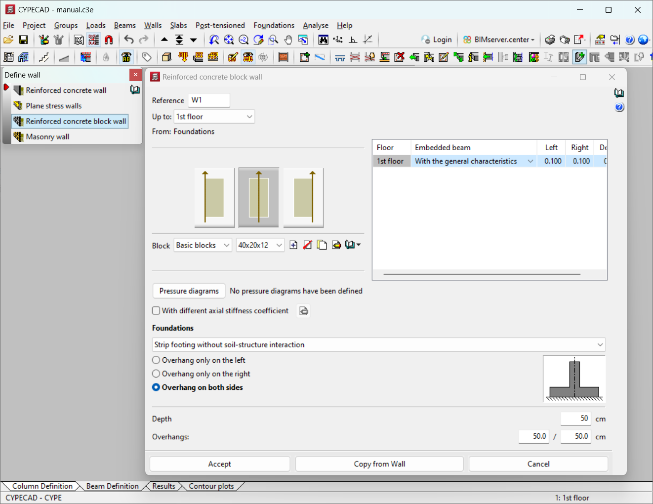
In the "Enter wall" window of the "Walls" menu ("Beam definition" tab), users can select "Reinforced concrete block wall", and the following data must be defined:
- Reference
- Group of floors where the entered wall starts and ends. Depending on the selection, the table on the right will be filled in, indicating: floor, embedded beam, left, right and edge.
- Placing the wall to the right, centred, or to the left of the entered line
- Selecting the block type and size. The block can be imported from the library or a new one can be created.
- Defining pressure diagrams. These can be defined if necessary.
- Marking (if necessary) "With different axial stiffness coefficient", stating the floor and the coefficient.
- Foundation:
- Fixity
- Strip footing without soil-structure interaction. In this case, the overhang(s) and depth must be specified.
- Strip footing with soil-structure interaction. For this option, the subgrade modulus must be set in addition to the above.
- Foundation beam. The left and right overhang, the depth, the allowable soil bearing pressures and the subgrade modulus must be specified.
- Other structural support. In this case, the left and right-hand overhang and the edge are established.
Using masonry walls correctly
Masonry walls should be used with caution, ensuring that the model entered conforms to the physical reality. They can be used in the following cases:
- Suspended floors
Built on the foundation plan at a reduced height (< 1 metre), leaving an air cavity that provides insulation. The direction of the masonry walls coincides with the column alignments of the structure. The different possible cases are listed below:- The foundation of the columns is made up of pad footings that will be analysed jointly with CYPECAD. In this case, when the columns have been defined with fixed support in the foundation, i.e. "with external fixity", to be compatible, the support of the masonry wall must be defined "with external fixity", with strip footing, setting the minimum dimensions required.
- The foundation of the building is a mat foundation. It is advisable to proceed in the same way as the previous case, i.e. to insert it but in this case "without external fixity", since the masonry wall is resting or bearing on the mat foundation, but a foundation beam must be inserted under the wall. The support beam, which will actually be embedded in the mat foundation, should be inserted with zero overhangs (no overhangs) and the slab edge. The subgrade modulus and soil bearing pressure should also be the same as the slab.
- The foundation of the columns of the building is by foundation beams, which coincide with the masonry walls. Users must analyse the reactions of the suspended floors as linear loads, and enter them on the foundation beams of the building.
- The foundation of the building is joint and composite, with footings, slabs and mat foundations. The problem is complex in this case, and it is advisable to refer to the previous sections, and to "Foundation slabs and beams".
- Masonry walls between floor slabs
If masonry walls are used to support part of an upper slab on a lower slab, it is important to ensure that the structural design and applied loads mean that the masonry wall is actually working in compression and transmitting loads, rather than behaving as a tie beam, for which it will be an unsuitable structural element. At this point, they are always defined as "without external fixity", giving the support beam the overhangs and edges considered appropriate.
The application of masonry walls is very broad, as they can be used for low-rise structures, such as load-bearing walls, support for lift machinery slabs, load-bearing walls for attic setbacks, and any type of load-bearing wall in the overall structure of a building.
Analysis and design process for reinforced concrete block walls
The reinforced concrete block walls are sized according to the corresponding standard and can be sized with only the strength of the blocks, or with filler concrete and horizontal reinforcements such as horizontal and vertical joint reinforcement, according to the specifications and verifications of the selected standard. The design and verification standard will generally be the Eurocode and the building code “Código Técnico de la Edificación” for Spain.
In reinforcement concrete block walls, the design strength values, specific weight, etc., given by the manufacturer or user are taken. Blocks from manufacturers such as the Spanish association of concrete block and masonry manufacturers NORMABLOC can also be used.
They can be designed with or without reinforcement. Design options are available in the case of vertical or horizontal reinforcement. The "Design concrete block walls" option in the "Beams/Walls" menu ("Results" tab) can be used. The program offers the possibility to make a manual adjustment of the structure, until obtaining a satisfactory design of its geometry, without having to analyse it every time we try with different dimensions.
From the previous menu, in the "Code check concrete block walls" option, users can see whether or not the checks carried out on the concrete block walls are compliant or not, as well as view and print the report of checks carried out. If there are checks that are not compliant, a warning will be displayed and they will be highlighted in red in the report.
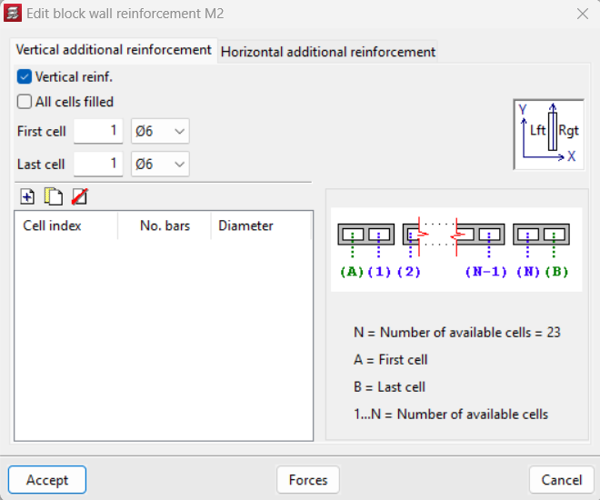
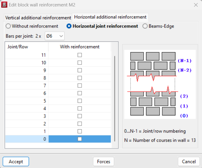
The reinforcement of the block wall can be edited from the "Edit walls" option in the "Beams/Walls" menu of the "Results" tab. Once the wall to be edited has been selected, vertical or horizontal reinforcement, or both, can be added. Among the options available in "Vertical additional reinforcement", users can select "Vertical reinforcement" and indicate the cells and whether or not they have infill or not. Under "Horizontal reinforcement" users can indicate "Without reinforcement" or use "Horizontal joint reinforcements" or "Beams-Edge" and define them if necessary.
Results output
The following reports can be obtained:
- Report of concrete block walls
Including: material description, summary check, composition, block quantities (elements) and check. - Forces and reinforcement of columns, shear walls and walls
Shows the shear wall forces (by loadcase), materials used (concrete and steel), etc.
User license
For CYPECAD to be able to analyse and design concrete block walls, the user license must include the "Reinforced concrete block walls" module in addition to CYPECAD.
Other features
To access other features offered by the program, several modules can be found on the "CYPECAD modules" page.