
Introduction
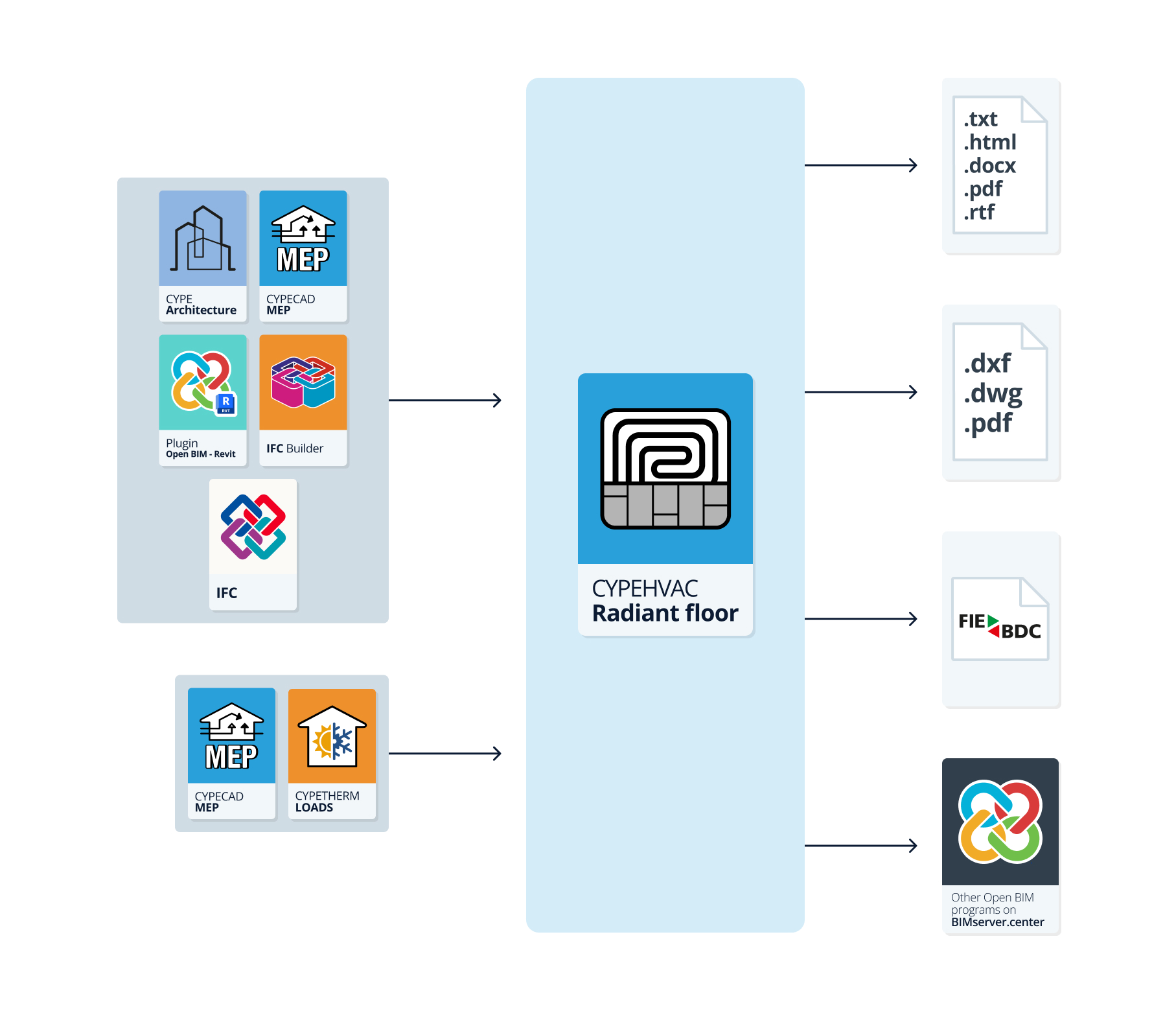
CYPEHVAC Radiant Floor is a BIM application for designing radiant floor heating and cooling systems. The program can import architectural models developed in IFC, and can be used to enter the system and design it with the help of different tools. Among the options offered by the program, the automatic entry of the radiant floor circuits, the updating of their layout, taking into account both the obstacles and the spaces, and automatically extracting the quantities of the materials needed for the complete installation of the systems stand out.

| Note: |
|---|
| CYPEHVAC Radiant Floor can be used to design generic radiant floor systems. To design radiant floor systems from a specific manufacturer, different specific applications can be used, such as Open BIM GIACOMINI, Open BIM ORKLI Radiant Floor, Open BIM POLYTHERM, Open BIM ROTH or Open BIM SAUNIER DUVAL. These applications have an interface and options similar to those offered by CYPEHVAC Radiant Floor. |
Workflows supported by the program
As CYPEHVAC Radiant Floor is an Open BIM tool and is connected to the BIMserver.center platform, it offers different workflow options.
Data entry
Free modelling/with templates
- System design by means of free entry in CYPEHVAC Radiant Floor.
- System design in CYPEHVAC Radiant Floor based on DXF-DWG, DWF, PDF templates or images (.jpeg, .jpg, .bmp, .wmf).
Importing BIM models
If the CYPEHVAC Radiant Floor job is linked to a BIM project from the BIMserver.center platform, the following actions can be carried out:
- Importing the model with the geometry of a building. This generates the floor plan of the building and imports the spaces from the spaces read from the BIM model, as well as generating obstacles from the geometry of elements such as columns. Among the options available are the following:
- Importing models designed in IFC Builder.
- Importing models designed in CYPE Architecture.
- Importing models in IFC format (generated by CAD/BIM programs such as Allplan, ArchiCAD and others) uploaded to the BIMserver.centre project via the web platform.
- Importing models designed in Autodesk Revit with the Open BIM - Revit Plugin.
- If the architectural model is generated by IFC Builder or CYPE Architecture, users can also import the DXF or DWG templates contained in that model, or those that the program itself generates (from the construction elements entered) when a model is exported to the BIM project.
- Importing the results of programs that can analyse thermal loads in order to be able to use them in the sizing of the system.
- Importing thermal loads from CYPETHERM LOADS.
Data output
- Exporting reports to HTML, DOCX, PDF, RTF and TXT formats.
- Exporting drawings to DXF, DWG and PDF formats.
- Exporting measurements to FIEBDC-3 format.
- Exporting the information generated with CYPEHVAC Radiant Floor to the BIMserver.center platform using IFC and GLTF formats. This allows it to be viewed by authorised project participants. The information generated by CYPEHVAC Radiant Floor can be used by the following programs:
- CYPEHVAC
Imports the CYPEHVAC Radiant Floor collectors and completes the modelling of the system.
- CYPEHVAC
Work environment
The program has a simple work environment that ensures that the system design can be carried out quickly, entering the elements in plan views.
The interface displays the folllowing:
- An upper toolbar containing tools for: managing project options; defining enclosures and obstacles; entering and editing the elements of the radiant floor installation, including circuits and peripheral areas, manifolds and connection pipes; inserting annotations; accessing editing tools; performing the analysis and checking of the system; and generating the roll quantities.
- The work area, on the right side of the screen, where the aforementioned elements are entered, edited and displayed.
- Finally, on the left-hand side panel are the tools for defining the different floor drawings of the building and navigating through them, as well as for viewing the 3D view of the system.

Data input and output sequence for designing and analysing radiant floor systems
Radiant floor systems can be defined and analysed in the program by means of the following input and output sequence:
- Creating a new job (from "File", "New").
- (Optional) Linking to BIMserver.center, selection and import of floor plans and enclosure types read from the BIM model.
- Setting the general options (from "Project", "General options"), including revision of libraries of enclosure types and facility elements.
- (Optional) If not read and generated from the BIM model, floor plans must be entered manually using the options in the left side panel.
- (Optional) If they have not been read and generated from the BIM model, the spaces must be entered manually (from "Enclosures", "New") in each floor plan in the work area.
- (Optional) Entry of existing obstacles (from "Enclosures", "Obstacle") in each floor plan in the work area and/or review of the obstacles generated in the process of importing data from the BIM model.
- Entering and laying out the radiant floor circuits in the spaces shown on each floor in the work area. This can be done in two ways:
- Individual input (from "Circuit", "Circuit").
- Automatic generation (from "Circuit", "Generate circuits").
- (Optional) (Optional) If necessary, circuits can be divided to adjust their geometry (from "Circuit", "Divide circuit").
- (Optional) If available, the peripheral areas are defined (from "Circuit", "Peripheral area") on the sides of the circuits.
- Defining the layout of the radiant floor circuits (from "Circuit", "Layout") by clicking on each circuit.
- Laying out the radiant floor manifolds (from "Distribution", "Manifold") on each floor in the work area.
- Entering connection pipes (from "Layout", "Connection pipe") between the circuits and the underfloor heating collectors in each drawing in the work area.
- System analysis, consulting results on screen and in result reports ("Analysis" group).
- (Optional) Managing and generating roll quantities (from "Quantities", "Roll quantities").
- Obtaining reports, drawings and the bill of quantities (from "File", "Reports/Plans/Export").
- Export to BIMserver.center (from "BIMserver.center", "Share").
Examples of radiant floor system models
Below is an example of a radiant floor system that can be developed in the program, indicating the layout of the elements and the options that allow them to be entered in the model:
Installing a radiant floor in a single-family dwelling
- Spaces (imported from the BIM model or entered from "Spaces", "New").
- Obstacles (from "Spaces", "Obstacle").
- Circuits (from "Circuit", "Circuit" and "Layout").
- Peripheral area (from "Circuit", "Peripheral area").
- Collector (from "Distribution", "Collector").
- Connection pipes (from "Distribution", "Connection pipe").


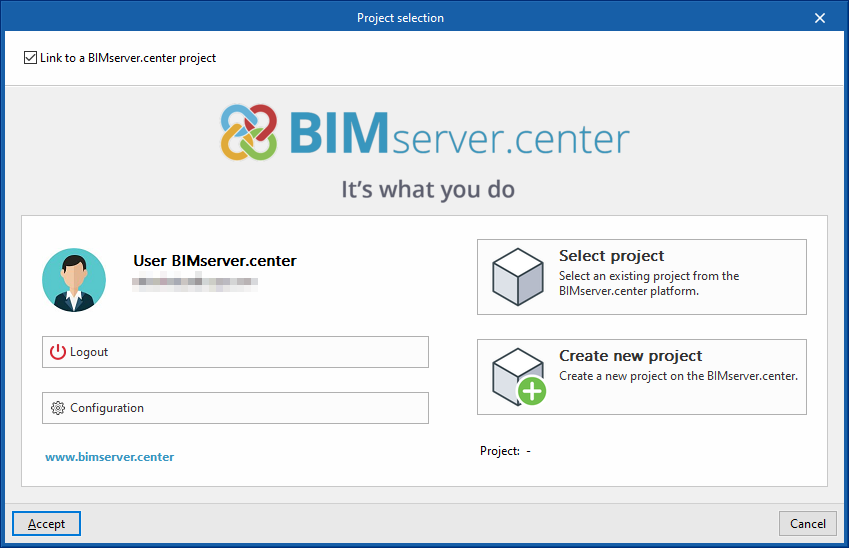
Creating a new job, linking to a project and importing data
When launching the application and clicking on "New", it is possible to create a "New job". After entering the "File name" and "Description", the job can then be integrated into an existing project in BIMserver.center.
This is done in the "Project selection" window, which has the following options:
- On the left-hand side, users can log in with a BIMserver.center account.
- On the right-hand side there is a "Select project" option to choose an existing project. There is also the possibility to "Create a new project". In this case, the created project will be visible from BIMserver.center from that moment on.
- There is the option to start the project without being linked to the BIMserver.center platform. To do this, simply uncheck the "Link to a BIMserver.center project" box at the top left.
Once the new job has been created, the general interface of the program is accessed, after going through the import wizard, if necessary. At any later time, during the work process, project files can be shared or imported via the "BIMserver.center" group, located at the top right of the general interface.

Importing BIM models
When creating a new job, if a project hosted on the BIMserver.center platform has been selected from "Select project", the "Import BIM models" window appears, which shows the files contained in this project in IFC format.
The application offers users the possibility of including one or more of the existing models in the project. To do so, check the "Import" box and accept it. The “Type” of each file must be set to “Starter” or “Additional”.
Subsequently, the 3D view of the program will display the imported models, both from the initiator and additional files. In addition, the program can import the geometry of floors and spaces from the file marked as the initiator by means of a configuration wizard.

Configuration wizard: selection of floor drawings and space types to be imported
From the "Import BIM models" window, the program opens the "Configuration" wizard, which consists of the following steps:
- In the first step, a report with the floor plans found in the BIM model is displayed. Here, the floor plans to be imported can be selected. The spaces included in a floor plan that has not been selected will not be imported.
| Note: |
|---|
| To modify, enter or delete drawings of the project at a later stage, the options on the left-hand side panel of the general interface can be used. |

- In the next step, a report with the space types found in the BIM model is displayed. Here, the space types to be imported can be selected. Spaces assigned to an unselected space type will not be imported.
| Note: |
|---|
| The imported space types must then be checked from the "Space types" option under the "General options" option in the "Project" group of the main toolbar. To enter the zones manually, use the "New" option in the "Spaces" group of the main toolbar. |

Import results
Finally, in the last step, an "Import results" table is displayed with the information of the processed, created, modified or deleted BIM model elements.

Layout of spaces and obstacles
The "Spaces" group in the main toolbar contains the options for inserting and arranging spaces and obstacles in the model:

New
Inserts a space in the work area by drawing its outline on the floor plan. There is no need to enter the spaces manually if they have been read and imported from the BIM model.
When entering a space, the program requires the following parameters to be defined:
- Reference
Space reference. - Type
Selection of the space type. The space types can be created and edited using the options available to the right of the drop-down menu or through the libraries available in "General options", within the "Project" group. - Thermal load
Activates and defines the thermal load of the space. In the case of spaces imported from the BIM model, this data can be read from the information provided in the BIM model.- Sensitive cooling load (optional)
- Heating load (optional)


Obstacle
Inserts an obstacle by drawing its outline on the floor plan. This represents the existence of fixed furniture, columns and other elements that impede the layout of the underfloor heating in certain parts of a space.
The program shall consider the geometry of the obstacle when generating a circuit layout.


Managing annotations
The "Annotations" group in the main toolbar contains the options to insert annotations such as texts, labels and dimensions on the drawings:

Annotations
The "Annotations" menu has the following options:
- Insert text
Inserts a box on the drawing with the text entered by the user. - Move tag
Moves the circuit or space information tag generated by the program. - Show/Hide tag
Shows or hides the information tag of the circuits or spaces generated by the program. - Insert dimension
Inserts a linear dimension between the two selected points on the drawing. - Measure lengths on plan
- Directly measures the length between two selected points on the drawing.

Editing tools
The "Edit" group in the main toolbar contains the tools for editing the model elements:

The following options are available:
| Edit | Edits the parametric properties of the selected element in the model. | |
| Delete | Deletes a previously entered item. | |
| Move | Moves an element or a node of an element. | |
| Move a group of elements | Moves a group of elements. | |
| Rotate | Rotates an element on plan. | |
| Rotate a group of elements | Rotates a group of elements with respect to the centre and with the angle of rotation marked by two points on the plan. | |
| Copy | Creates a copy of one or more elements. | |
| Assign | Assigns the parametric properties of the selected element to other elements. | |
| Symmetry (copy) | Copies a selection of elements with symmetry about an axis defined by two points. | |
| Symmetry (move) | Moves a selection of elements with symmetry about an axis defined by two points. | |
| Insert node | Inserts a node at the selected point of a pipe. | |
| Copy onto another floor plan | Creates a copy of the selected elements on the desired floors. After selecting the elements to be copied, check the boxes of the floors where you want the elements to be copied. | |
| Selection of elements | Activates or deactivates the category of items to be edited: - Distribution: Spaces - Radiant floor: Manifolds, Circuits, Layouts, Connection pipes, Obstacles |
Results output
The analysis results can be obtained in the following ways:
Viewing results on screen
After carrying out the analysis, by selecting the "Consult results and checks" option in the "Analysis" group, CYPEHVAC Radiant Floor displays the results in the tooltip or information text that appears when the cursor is positioned on an element of the installation, such as the spaces, circuits or collectors, as well as the compliance of the checks carried out on it. To do this, the "Show information texts" option in the top right-hand toolbar must be checked.

Reports of results by element
The corresponding report of results for each element can be accessed by using the "Consult results and checks" option in the "Analysis" group and clicking on the circuits or collectors.
These reports show a summary of the analysis results of the selected element and detail the analysis expressions used, as well as the analysed quantities and the set value limits.

Job reports
The program can print the reports directly or generate HTML, PDF, TXT, RTF or DOCX files.
The reports are obtained via the "Reports" option in the "File" menu or in the top toolbar.
- Overview calculations
This shows a report with the calculation basis, design and quantities of radiant floor systems. It also includes an appendix with the expressions for the calculation of the heat flow from the pipes described in the EN 1264 standard and used by the program.

- Analysis results
Displays information on the results that have been calculated for the system entered, organised in the following sections:- Material schedule
- Summary of results
- Pipe rolls and subdividing in circuits
- Radiant floor circuits, by space
- Manifolds
- Capacities provided by the circuits
- Contribution to the service areas


- Material schedule
Displays the material schedule with the quantities of the elements arranged in the system, such as panels, pipe coils or radiant floor manifolds.

- Drawings
With this option, the program can print the drawings as reports so that they can be printed and exported as another document.

Drawings in DWG, DXF or PDF format
The program can print the drawings of the job on any graphic peripheral configured on the computer, or create DWG, DXF or PDF files.
Editing the drawing allows the following options to be configured:
- Drawing floor plans
- Details
The drawings can be obtained via the "Drawings" option at the top of the interface or via the "Reports" option in the "File" menu.


Bill of quantities in BC3 format
Using the "Export" option and, in turn, "Export in BC3 format", from the "File" menu or from the top toolbar, CYPEHVAC Radiant Floor allows the system bill of quantities to be obtained in FIEBDC-3 (BC3) format.
GLTF file compatible with BIMserver.center
When the project is exported to the BIMserver.center platform, a 3D model is automatically exported in GLTF format to integrate the installation model into the Open BIM project, allowing it to be visualised:
- on the online platform;
- in the BIMserver.center app for iOS and Android;
- in virtual reality and augmented reality;
- in other CYPE programs.
Integration into the BIMserver.center platform
Many of CYPE's programs are connected to the BIMserver.center platform and allow collaborative work to be carried out via the exchange of files in formats based on open standards.
Please note that, to work on BIMserver.center, users can register on the platform free of charge and create a profile.
When accessing a program connected to the platform, the program connects to a project in BIMserver.center. This way, the files of the projects that have been developed collaboratively in BIMserver.center are kept up to date.

| More information: |
|---|
| For further details related to using CYPE software via the BIMserver.center platform, please click on this link. |


