DXF and DWG drawings
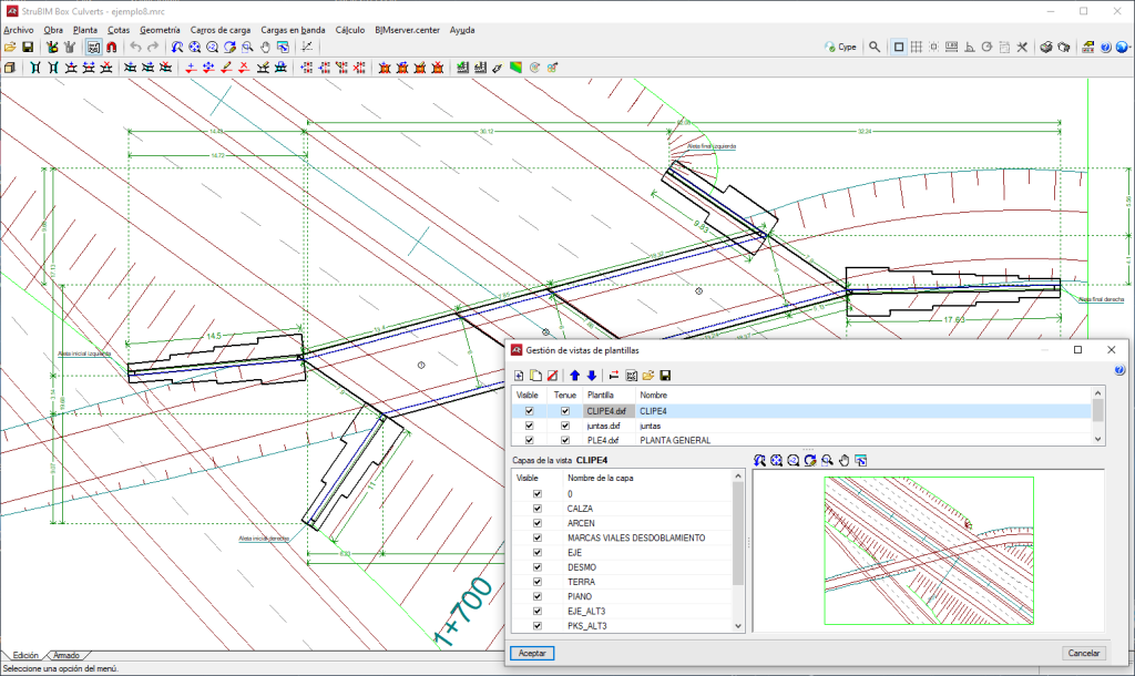
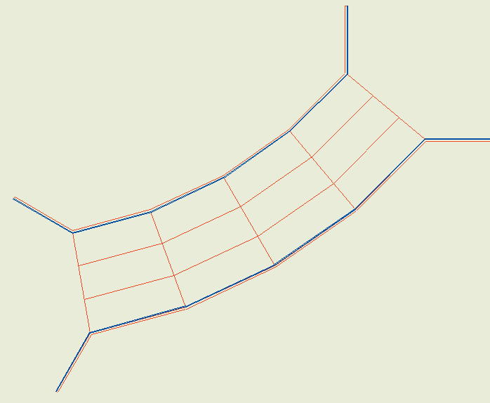
DXF and DWG files can be used as templates for entering the geometry on the plan when assistants aren’t used. If the box culvert drawing is generated with the DXF and DWG file in the background, the template will appear in the drawing.
The geometry is entered via the "Floor" menu options. First of all, the adjustment lines of the lateral walls must be entered. Please note that, by default, the inner faces of the lateral walls are aligned with the adjustment lines, so when entering the adjustment lines, this should be carried out bearing in mind that they are the inner faces of the lateral walls and, therefore, the separation between the right and left lateral wall is the free span. This menu also allows users to indicate which are the joints.
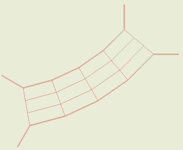
Although it is not essential, if there is a DXF or DWG file where the lateral walls are entered in plan (preferably the line of the interior face), entering the geometry of the frame will be much quicker.
Using the DXF or DWG file as a template for entering the lateral walls is beneficial in comparison to entering them by coordinates, and may be the method used when not using the assistants. When using a DXF file from the CAD program and before exporting, it should be noted that the number should be 3 decimal places. Also, the unit of measurement when importing DXF or DWG is the metre. To import the DXF or DWG file into the program's own format, the following steps must be followed:
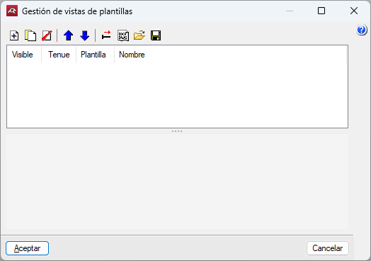
- Select the "Edit templates" icon in the toolbar. The "Manage template views" window opens.
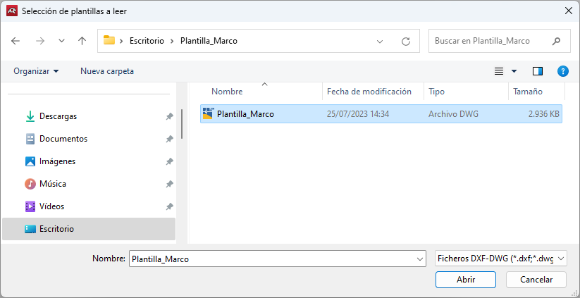
- Click on the "Add" icon, which will open the "Selection of templates to read" window. Choose between DXF or DWG. Browse for the file, select it and click "Open".
- Click "Accept" to return to the "Manage template views" window and click "Accept" again to display it on screen.
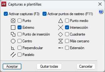
- To use the snaps, click on "Template object snaps" in the toolbar and activate, "Intersection" or "End", for example.
The "New left lateral wall point" option can be used to enter the points of the segments that make up the left lateral walls. The next point always establishes a new lateral wall with respect to the previous point, therefore, the entry must start with the end of the left-hand starting wingwall, continue with the left-hand lateral walls of the modules and end with the left-hand end wingwall.
The "New right lateral wall point" option is used to enter the right lateral wall.
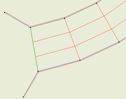
The "New joint" option can be used to indicate the cross faces of the modules. To do this, click on a point in the lateral wall on one side and then the opposite point in the lateral wall on the other side. After entering the two joints, the corresponding module is generated. Once the left and right lateral wall ends have been defined, the joints are inserted.
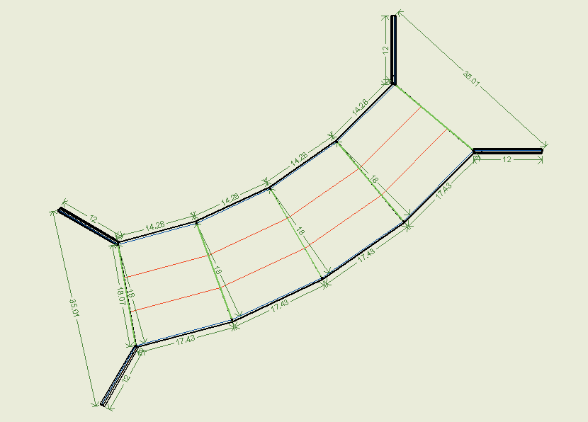
Then, after inserting the second joint, the program creates a module (the lateral wall thicknesses are visible) and the wingwalls. After entering the third joint, the second module is created.
Finally, when the last joint is fitted, the floor insertion is completed.

