One of the main advantages of the Open BIM workflow is the possibility of using tools from different developers in the same project through exchange formats. However, one of its main limitations is that the quality of interoperability is dependent on the ability of each program to read and write IFC entities.
A typical example is Revit, whose two-way communication via IFC leads to a considerable loss of model information, particularly when transferring information from other applications. Now, with the latest update of the Open BIM for Revit Add-in on BIMserver.center, it is possible to send information from other tools to Revit in native format. This article will review these new features in the communication with CYPECAD.
Contents
- Exporting the IFC from CYPECAD
- Synchronisation of Autodesk Revit with the Open BIM project
- Creating or loading families and types in Autodesk Revit
- Creating a mapping table between IFC classes and native entities
- Converting IFC to native
- See a video example
Exporting the IFC from CYPECAD
In this example CYPECAD will be linked to Revit so that the information generated in the BIM project will be available in both tools and synchronised via BIMserver.center.
We will start by linking the CYPECAD project with BIMserver.center. To do this, we will use the “BIMserver.center” option, in the top right corner of the “Beam definition” tab. Using the “link” option, we will choose a project previously created on BIMserver.center, or we will create a new one with the option “Create new project”.
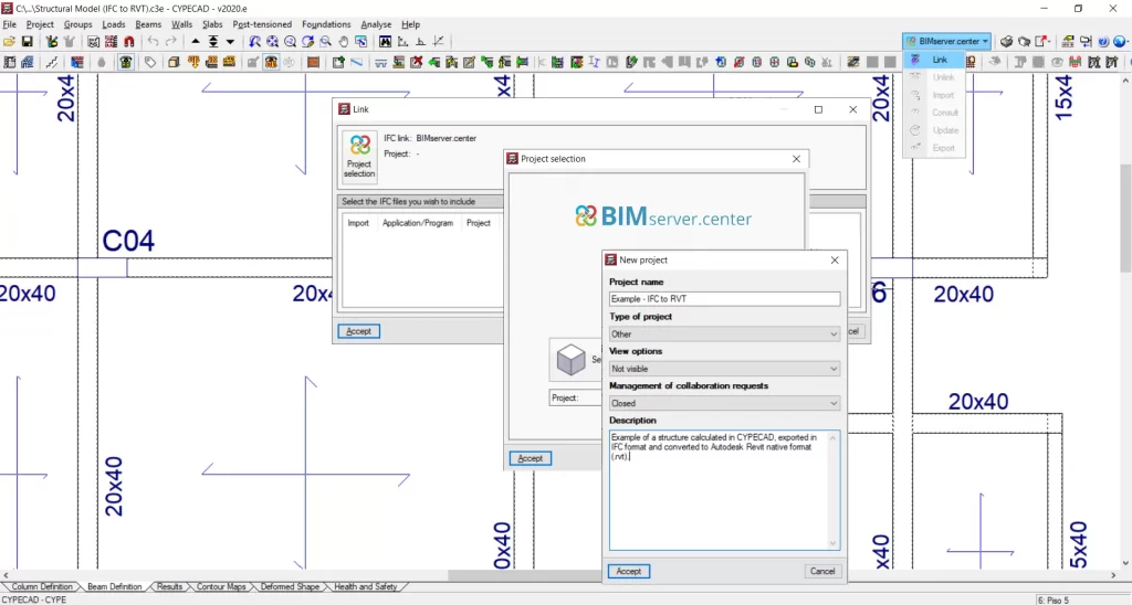
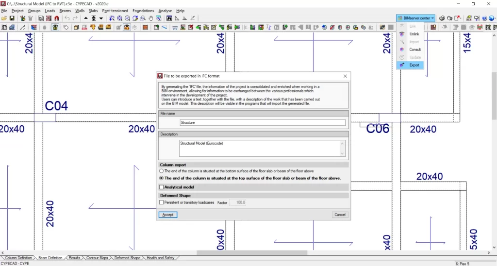
Once CYPECAD has been connected with an Open BIM project from BIMserver.center, we will return to the “BIMserver.center” menu and click on “Export”. The structural model in IFC will be exported to the platform.
Synchronisation of Autodesk Revit with the Open BIM project
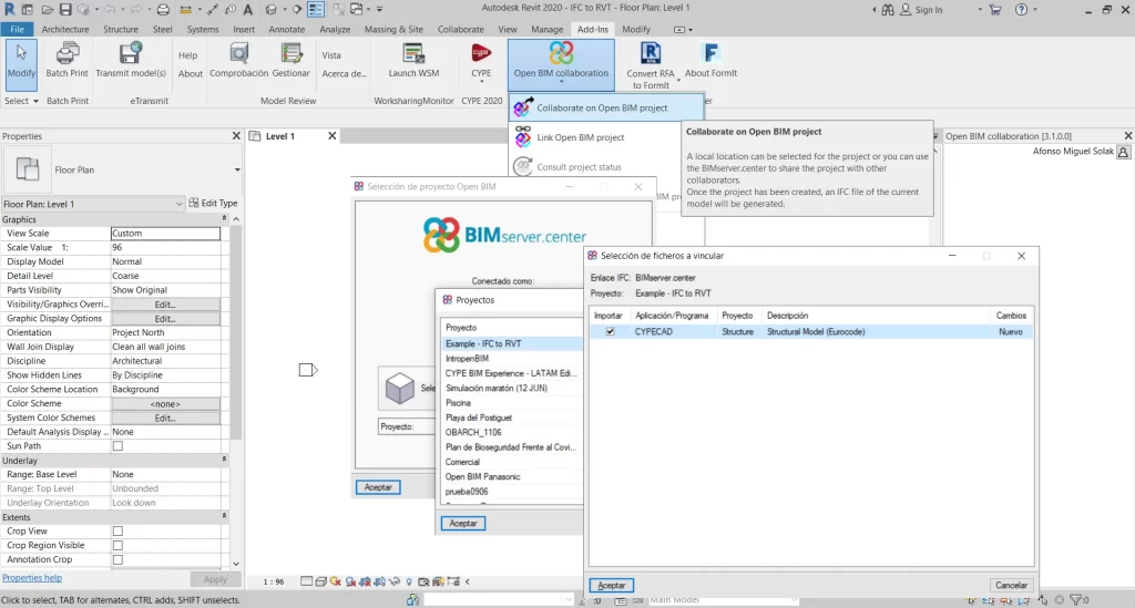
To transfer the CYEPCAD IFC model to Revit, we will use the Open BIM-Revit Add-in, which can be downloaded for free from this link.
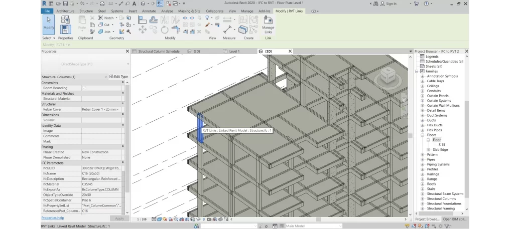
Similarly to CYPECAD, we will first link the Revit file to the Open BIM project on BIMserver.center. Once the link has been established, the files available in the Open BIM projects folder can be selected, which will be synchronised with Autodesk Revit as an IFC link. In this case, we select the structural model created in CYPECAD.
Creating or loading families and types in Autodesk Revit
Once the structure in IFC format has been imported, we will start the process of creating the .rvt model, whichwill act as a mirror of the BIMserver.center model. To do this, we will have to create (or load) the Revit families and types that in the following step correspond to the IFC classes and types of the structural model.
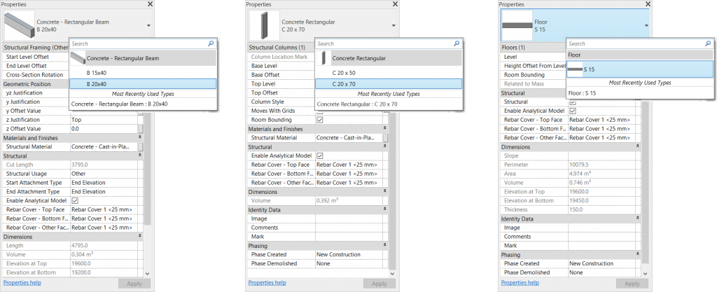
In this particular example, the following types were used:
Columns (Family and Type): family loaded from the United Kingdom library. Two types were created:
- Concrete Rectangular: C 20 x 50
- Concrete Rectangular: C 20 x 70
Beams (Family and Type): family loaded from the United Kingdom library. Two types were created:
- Concrete - Rectangular Beam: B 15x40
- Concrete - Rectangular Beam: B 20x40
Floors (Type): generic floor. One type was created:
- S 15
Creating a mapping table between IFC classes and native entities
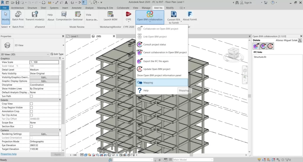
In this step we will create a table to correlate elements of the IFC file with Revit elements (families or types). To do this we will use the “Mapping” option.
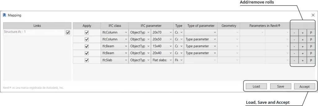
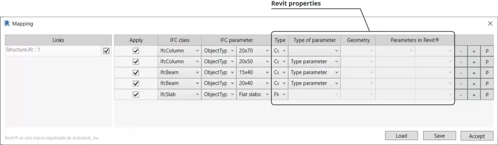
The “Mapping” table will be divided into four main parts:
Mapping lines: correlations between the IFC classes and types and Revit elements can be created. By using the “+” and “-” options (on the right), correlation lines can be added. The correlations created are reusable in future projects that contain the same Revit entities from the same template by using the “Save” and “Load” options respectively.
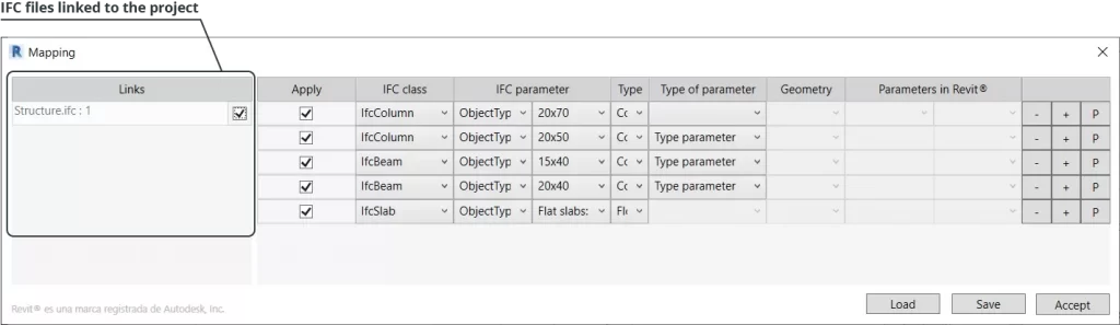
IFC files linked to the project: here the IFC files can be selected whose entities will be converted to native. All the linked project IFC files will appear in this list.
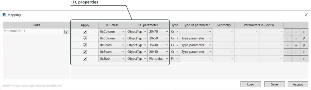
Properties of linked IFCs: in the “Apply” column we will define if the rule that is being created should be applied to the conversion. In the “IFC Class” column we will select an IFC class (IfcColumm, IfcBeam, IfcSlab, etc). In the “IFC Parameters” columns, the selected IFC class can be filtered by one of its available parameters.
Equivalent properties in Autodesk Revit: for each IFC Class combination and its respective parameters we will define the equivalent Revit entities and properties. There are various conversion configurations, which can be defined by using the “Type”, “Parameter type”, “Geometry” and “Parameters in Revit®” columns in combination.
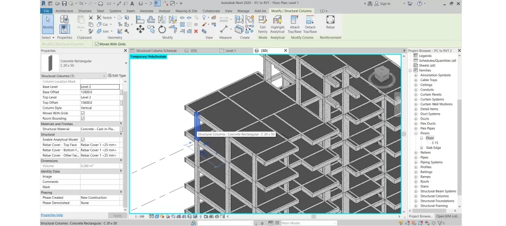
Converting IFC to native
Once the table has been created, we can click on “Accept” and Revit will start the process of creating new elements in the model, this time in native format, according to the previously defined equivalences.
The original IFC file will be kept intact and will remain linked to the project. The elements generated in native format can be edited, quantified or deleted, depending on the aims and requirements of the project.