
Introduction
CYPE Sewerage is a program developed for the analysis, design, checking and automatic sizing of sewerage networks in urban infrastructures, or branched sewers, with a single point of discharge and operating by gravity.
The aim in the design of these networks is to evacuate the water from the collection wells to the discharge point. For this purpose, the data and positions of the collection wells and the sewage dump are defined, as well as the layout of the network. In the analysis, the appropriate cross-sections of the sewerage pipes are obtained and it is checked whether the installation complies with the design limitations imposed.
| Note: |
|---|
| Together with other urban infrastructure programs such as CYPE Water Supply and CYPE Gas Supply, other aspects related to the installation design of housing estates can be solved. |
Work environment
The program has a simple work environment that allows the network design to be carried out quickly by entering and distributing the elements in a single work area on the floor plan.
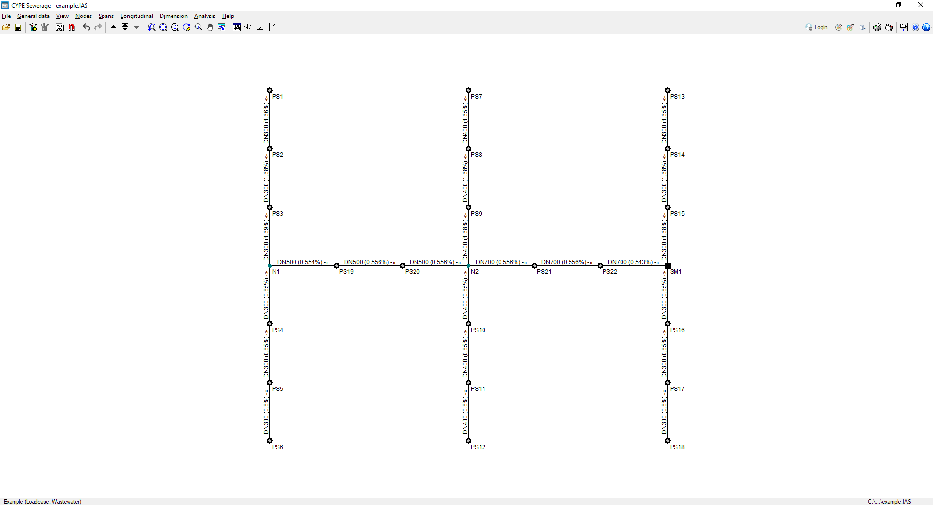
The interface shows the following:
- The menus at the top, where there are tools for:
- accessing the "File" menu;
- configuring the general data;
- controlling the display of the model;
- entering and editing nodes and sections;
- accessing the dimensioning options;
- analysing and designing the network;
- and accessing the "Help" menu.
- The options in these menus also appear in the drop-down options bar, which by default is hidden on the right-hand side.
- An auxiliary horizontal bar, under the menus at the top, where there are tools for:
- accessing the file manager and saving the job;
- accessing the editing resources;
- managing the templates and their snaps;
- undoing and redoing;
- navigating through the different combinations of hypotheses;
- modifying the drawing views;
- viewing the complete drawing map, rotating it, activating orthogonality and controlling the tools for entering by coordinates;
- consulting and managing the connection with BIMserver.center;
- viewing the 3D view of the installation;
- printing the reports and drawings of the job;
- showing or hiding the side drop-down bar of options;
- accessing the available help;
- and accessing the general configuration options.
- Finally, in the central work area, which occupies most of the interface, the elements that make up the network are entered, edited and displayed, as well as the topographic curves, if a model with terrain information has been imported.
Results output
Viewing results on screen
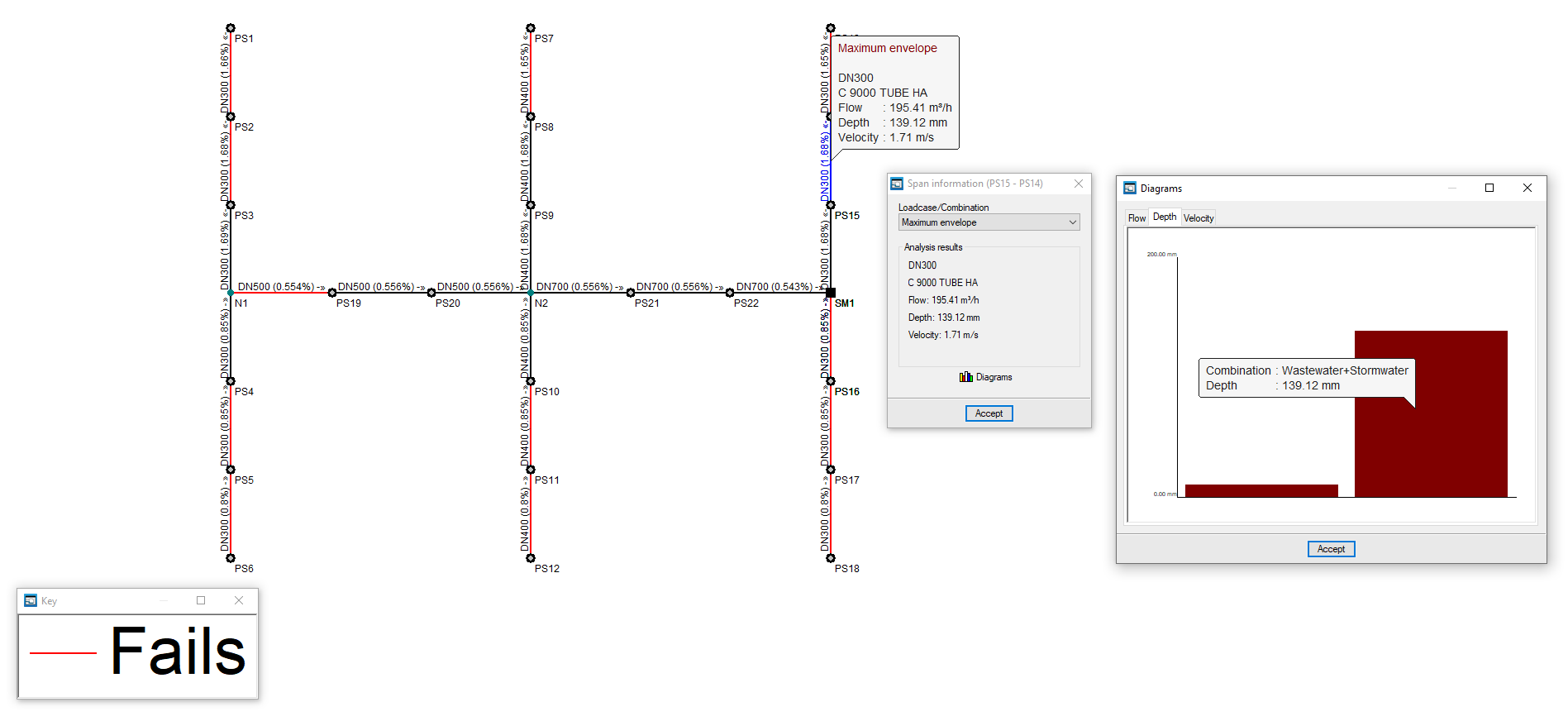
After the analysis, the program displays the results on the screen when selecting an element of the installation via "Nodes", "Information", or via "Sections", "Information".
This includes the analysis data of the nodes and the analysis data of the sections, with results by laodcases, combinations or envelopes.
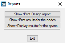
Reports
The program can be used to print the reports directly or to generate HTML, PDF, TXT, RTF or DOCX files.
The reports are obtained via the "Reports" option in the "File" menu or from the right-hand side of the top toolbar.
The following reports are available:
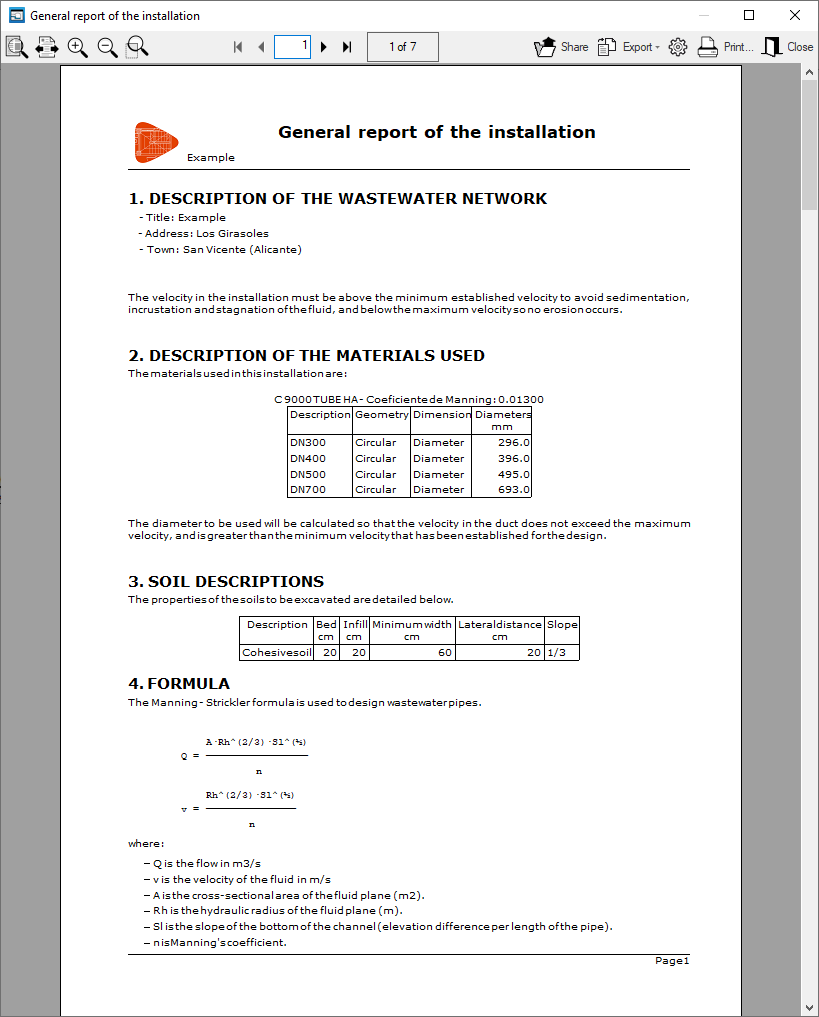
- Calculation report
Prints the general report of the installation. It includes the following sections, which can be activated or deactivated:- Gas network description (optional)
- Description of the materials used (optional)
- Soil descriptions (optional)
- Formula (optional)
- Combinations (optional)
- Node report (optional)
- Span report (optional)
- Envelope (optional)
- Quantities (optional)
- Excavation measurements (optional)

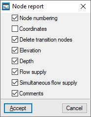
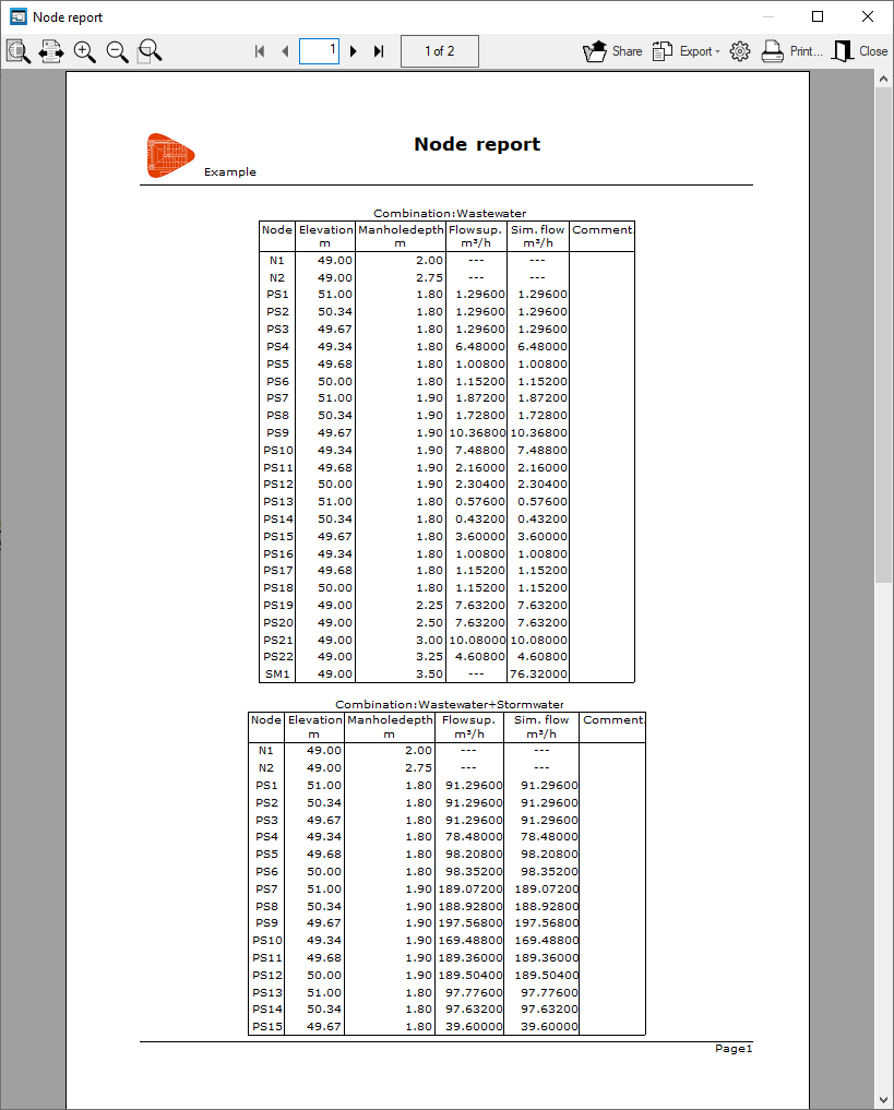
- Node report
Prints the report of the results in the nodes. It includes the following information, which can be activated or deactivated:- Node numbering (optional)
- Coordinates (optional)
- Delete transition nodes (optional)
- Installed flow (optional)
- Required flow (optional)
- Piezometric head (optional)
- Available pressure (optional)
- Comments (optional)
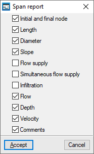
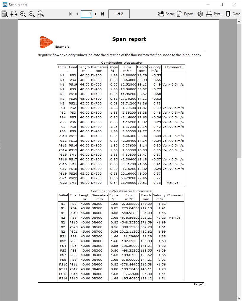
- Span report
Prints the report of the results in the spans. It includes the following information, which can be activated or deactivated:- Initial and final node (optional)
- Length (optional)
- Diameter (optional)
- Installed flow (optional)
- Required flow (optional)
- Flow (optional)
- Velocity (optional)
- Losses (optional)
- Comments (optional)
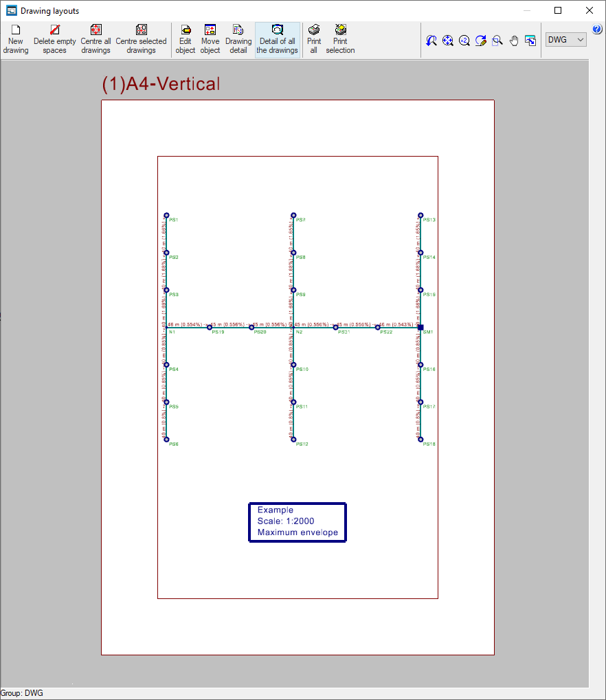
Drawings
The program can print the job drawings on any graphic peripheral configured on the computer or create DWG, DXF or PDF files.
The drawings are obtained from the "Drawings" option in the "File" menu or from the right-hand side of the top toolbar.
The following drawings are available:
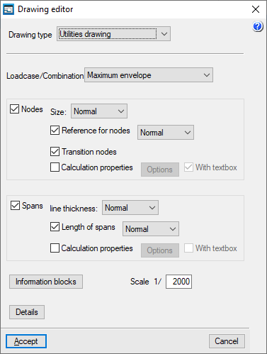
Utilities drawing
Shows the drawing of the installation on the plan.
The editing of the drawing offers the following options:
- Loadcase/Combination
Selects the loadcase, combination, envelope or oscillation for which data is to be displayed in the drawing. - Nodes (optional)
Displays the input information and analysis results of the nodes:- Size
- Node references (optional)
- Transition nodes (optional)
- Calculation properties (optional)
- Options: Flow, Depth, Ground level elevation, Elevation fill
- Spans (optional)
Displays the input information and analysis results of the spans:- Line thickness
- Length of spans (optional)
- Calculation properties (optional)
- Options: Dimension, Material, Flow, Pressure drop, Velocity
- Information texts
- General information table (optional)
- Quantities information table (optional)
- Excavation information table (optional)
- Scale
- Details
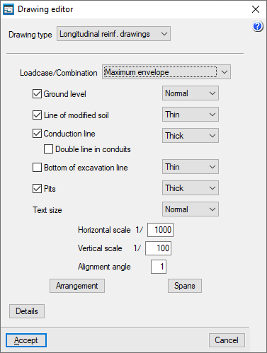
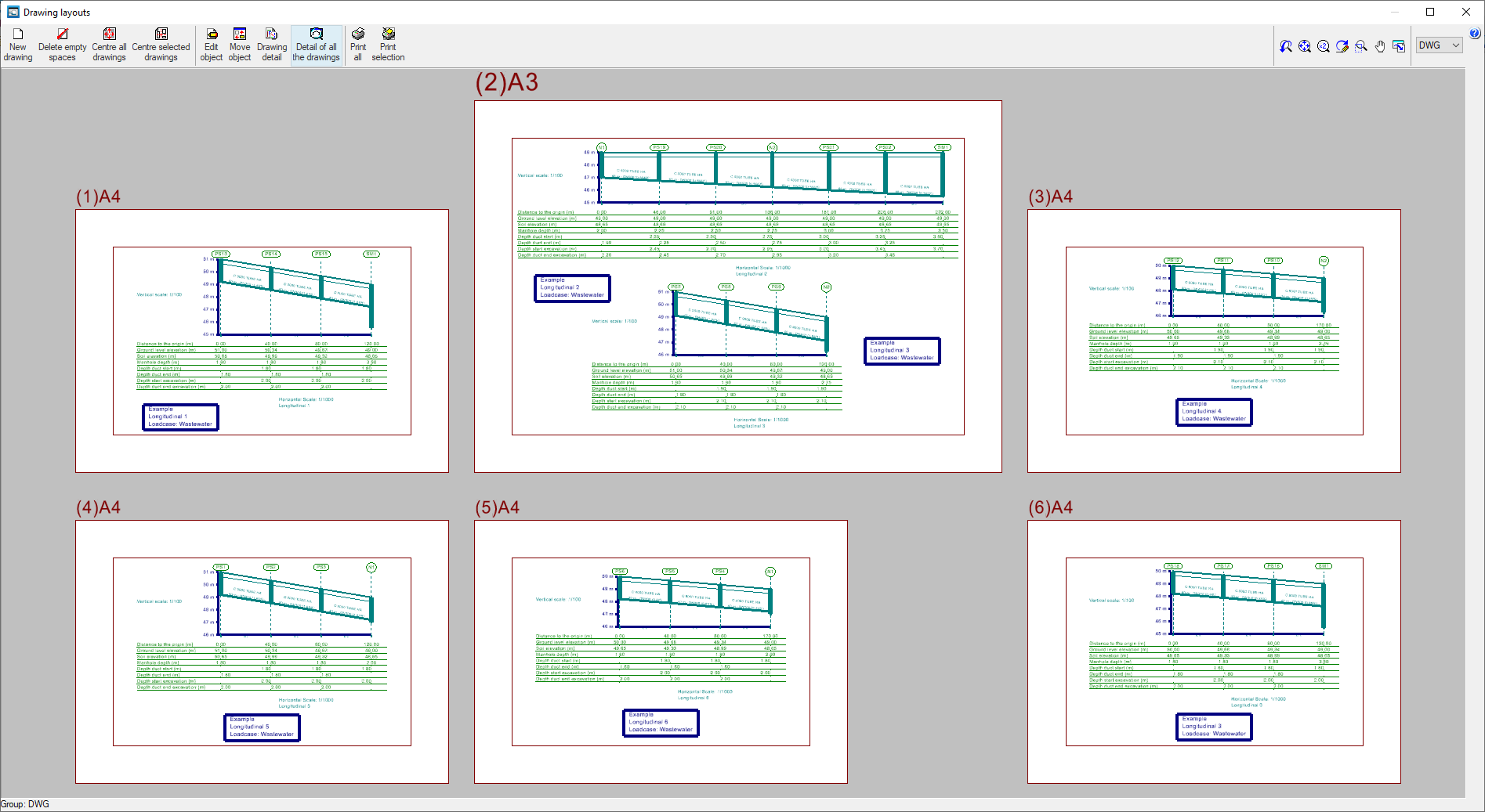
Longitudinal section drawings
Shows the longitudinal sections of the installation.
The editing of the longitudinal profile drawing offers the following options:
- Loadcase/Combination
Selects the loadcase, combination, envelope or oscillation for which data is to be displayed in the drawing. - Line thickness setting:
- Ground level (optional)
- Line of modified soil (optional)
- Conduction line (optional)
- Double line in conduits (optional)
- Línea de fondo de excavación (optional)
- Pits (optional)
- Text size
- Horizontal scale
- Vertical scale
- Alignment angle
- Arrangement
Edits the data to be displayed in the information arrangement under each longitudinal section. - Spans
Edits the data to be displayed on each section of the longitudinal section. - Details
GLTF file format compatible with BIMserver.center
If the job has been linked to a BIMserver.center project, a 3D model is generated in GLTF format to integrate the system model into the project when it is exported to the platform, allowing it to be visualised:
- on the online platform;
- on the BIMserver.center app for iOS and Android;
- on virtual reality and augmented reality;
- on other CYPE programs.
Integration into the BIMserver.center platform
Many of CYPE's programs are connected to the BIMserver.center platform and allow collaborative work to be carried out via the exchange of files in formats based on open standards.
Please note that, to work on BIMserver.center, users can register on the platform free of charge and create a profile.
When accessing a program connected to the platform, the program connects to a project in BIMserver.center. This way, the files of the projects that have been developed collaboratively in BIMserver.center are kept up to date.

| More information: |
|---|
| For further details related to using CYPE software via the BIMserver.center platform, please click on this link. |


