
Beam entry
To enter beams in CYPECAD, open the "Beam input" tab and move to the required group using "Move up group", "Go to group" and "Move down group".
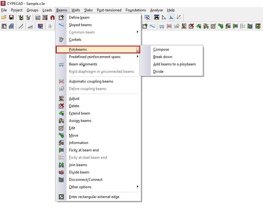
Then, in the "Beams" menu, select "Enter beam".
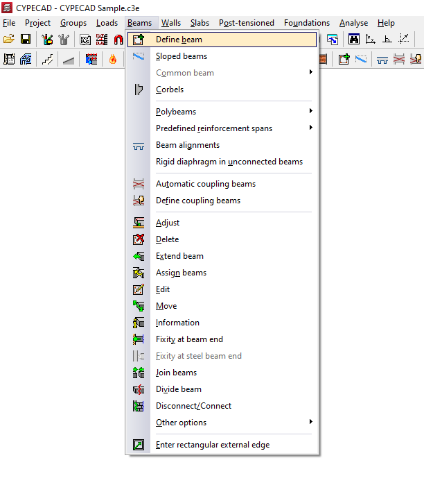
Selection of the current beam
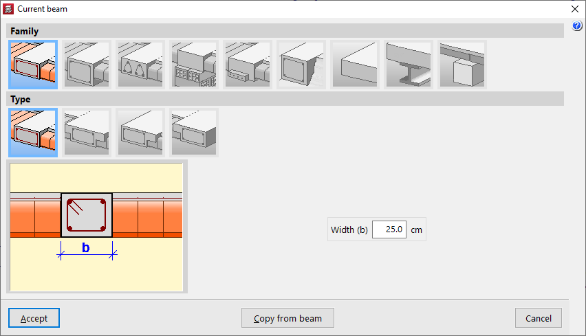
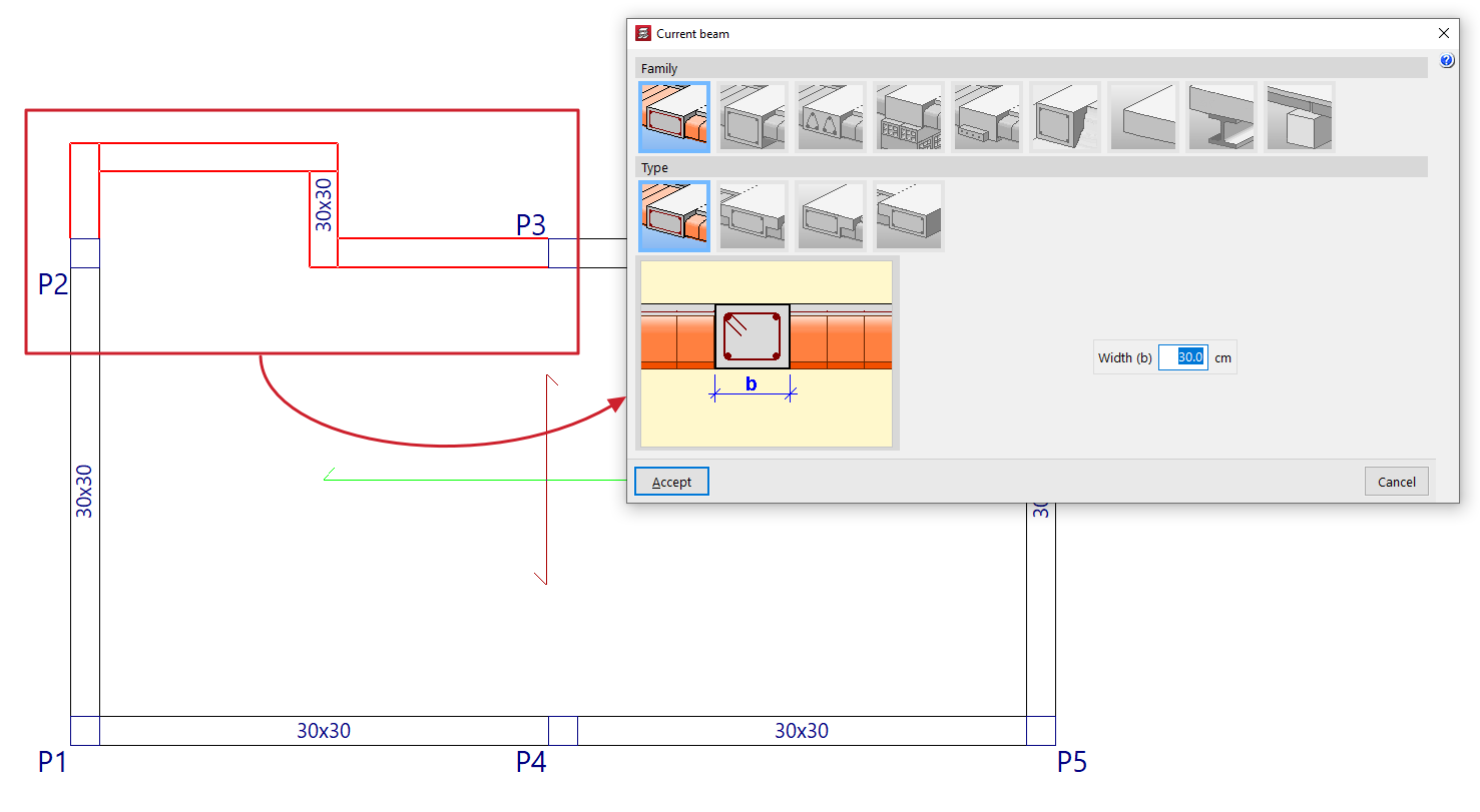
The program displays the "Current beam" window, where you can define the "Family" and "Type" of the beam to be entered, as well as its dimensions and properties.
The available families include:
- Flat beams
- Downstand beams
- Truss beams
- Beams with external restraint
- Prestressed beams
- Foundation beams
- Non-structural ring beam or boundary
- Steel beams
- Timber beams
All the values described above can be taken from an existing beam by clicking "Copy from beam" and then selecting another beam in the project with its information already defined.
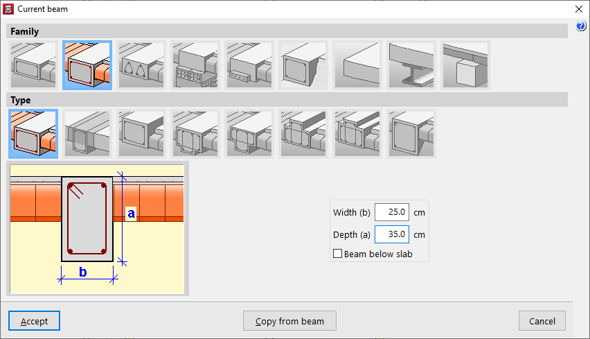
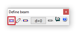
You can also access this window later by clicking the first option in the dialog box that appears while entering the beam, "Selection of the current beam".
Selection of the beam entry mode
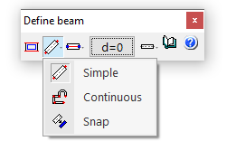
After confirming the beam type selection, choose the "Selection of the beam entry mode" from the drop-down list.
- "Simple" mode allows you to enter beam spans one by one by clicking on the start or end point.
- "Continuous" mode allows you to enter a sequence of beam spans through successive clicks. To finish, right-click and select "Finish entry". You can also "Delete last point" or "Delete all".
- "Snap" mode automatically converts a polyline or line from a DXF or DWG template into a series of CYPECAD beams by clicking on it. Depending on the pointer position, the beam is entered centred on or offset to one side of the selected line.
In the first two modes, you can use automatic snapping to previously entered columns and beams, as well as the "Template snaps" available from the corresponding button on the top toolbar.
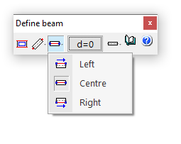
Selection of the alignment
The "Selection of the alignment" button allows you to specify whether the beam is placed at the "Centre", "Left" or "Right" of the entered line.
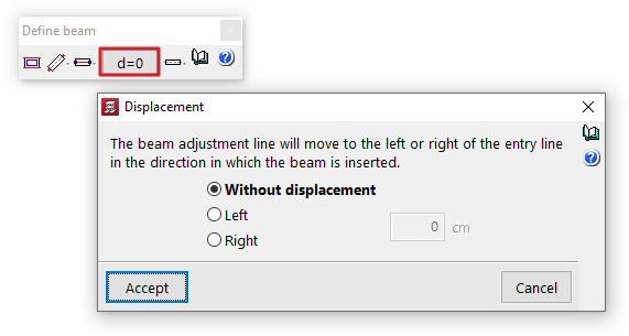
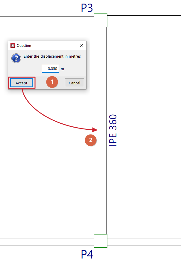
Displacement
The "Displacement" option allows you, during beam entry, to shift the alignment line by a specified distance to the left or right of the entry line, always in the direction of beam insertion.
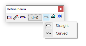
Straight and curved beam spans
The "Entry mode" option allows you to enter straight beam spans ("Straight") or "Curved" spans to model curved beams. In the latter case, in addition to the start and end points of the span, you must click a point along the arc to define the curved segment.
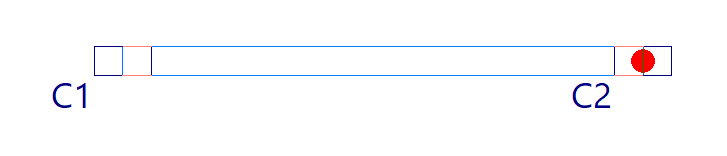
Beam layout in plan
Once the beam definition is complete, click "Accept". At this point, depending on the selected entry mode, you can move the pointer over other elements such as columns and beams to snap to them. You can also use snaps to previously entered templates.
Beam selection
To access the beam selection panel in CYPECAD, go to the "Beam input" tab. Then, from the "Beams" menu, select the "Enter beam" option to display the "Current beam" window. If you need to access this window later, you can click on "Current beam selection" in the dialogue box that appears while entering the beam, or use the "Edit" option from the "Beams" menu.
This way, the program allows you to specify the "Family" and "Type" of the beam to be inserted, as well as its dimensions and characteristics.
The available beam families are described below.
Flat beams
"Flat beams" are those that have the same depth as the floor slab. The following types of flat beams are available:
- Rectangular flat beam
- Flat T-beam
- Flat beam with right-hand flange
- Flat beam with left-hand flange
Flat beams will automatically take the value of the depth of the panel in which they are located. Therefore, the programme only asks for the definition of its "Width (b)". If the beam is located between two panels with different depths, it will take the greater of the two. If it is located between two panels at different levels, the depth of the beam will increase to cover the difference in height.
Hanging beams
"Hanging beams" have a different edge to the floor slab. The following types of hanging beams are available:
- Rectangular suspended beam
You must specify its "Width (b)" and its "Depth (a)". If the "Beam under floor slab" box is checked, the upper face of the beam is aligned with the lower face of the floor slab. If it remains unchecked, it will be aligned with the upper face of the floor slab.
- Rectangular suspended beam with composite head
In this case, the length of the "Left flange (i)" and the "Right flange (d)" of the concrete section that will work in conjunction with the beam must also be indicated.
- Inverted rectangular beam
This type of beam keeps the lower face aligned with the lower face of the slab and places the edge above it.
- Hanging T-beam
- Hanging T-beam with head embedded in the slab
- Viga en 'T' invertida con cabeza embebida en el forjado
- Inverted T-beam
The T-beam options, whether suspended, inverted or with the head embedded in the slab, allow the definition of a reinforced section with this shape, using the options "Width (b)", "Edge (a)", "Left flange (i)", "Right flange (d)" and "Flange edge (s)" options where necessary.
- Rectangular suspended beam with variable section
This option allows you to define a beam with a variable section with a specific "Width (b)" and an "Initial depth (a)" that may be different from the "Final depth (c)".

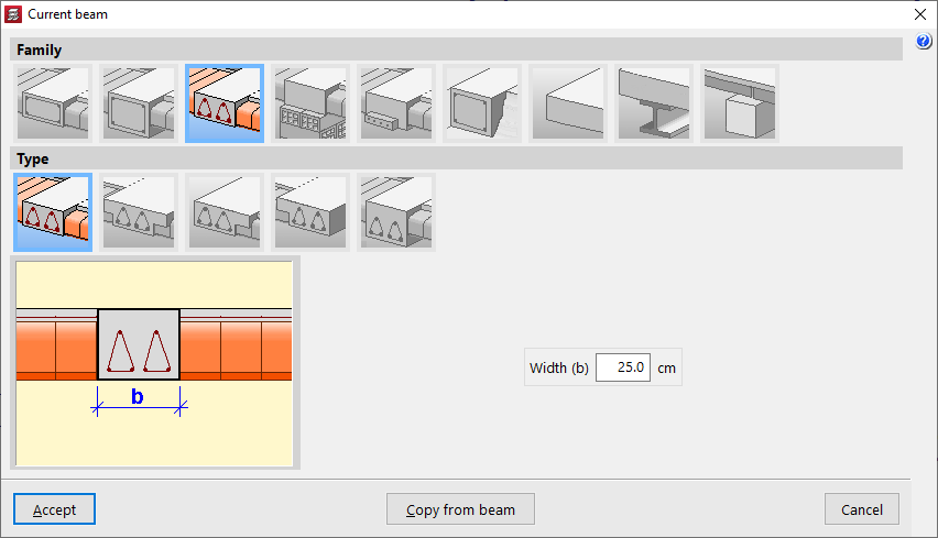
Lattice beams
"Lattice beams" are a type of beam with prefabricated reinforcement. Their characteristics must be supplied by the manufacturer and defined within the general project data ("Project"> "General data" > "By position" > "Beam options" > "Formwork arrangements" > "Lattice beams"). The following options are available:
- Rectangular flat lattice beam
- T-shaped lattice beam
- Lattice beam with wing on the right
- Lattice beam on the left
- Rectangular suspended lattice beam
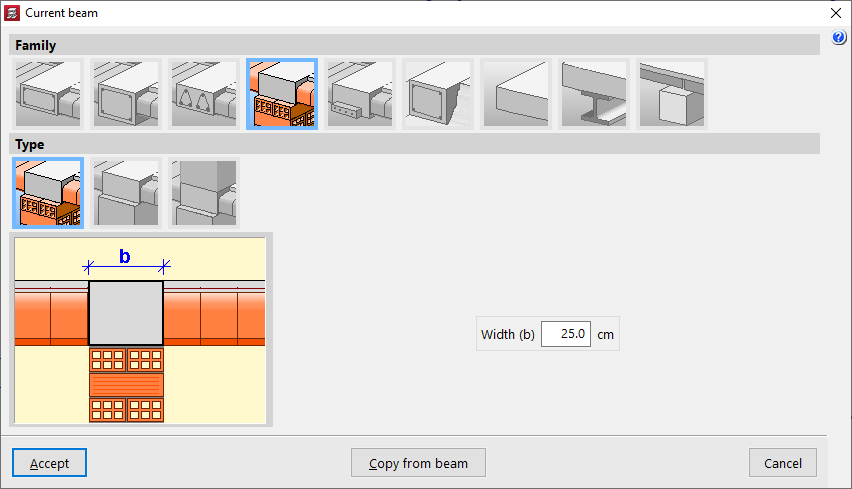
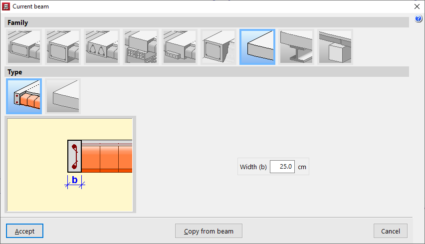
Beams with external connection
"External connection beams" allow you to simulate a linear support on which the rest of the modelled structure can rest. The following types of external connection beams are available:
- Wall support
This element only prevents movement on the vertical axis, allowing rotation and movement on the horizontal plane. It is used to simulate a movable or expansion support.
- Wall support
This element constrains all movements, both vertical and horizontal, but allows rotation. It is used to simulate a fixed articulated support.
- Embedding
This element constrains both displacement and rotation.
In all three cases, the program only requests the "Width (b)" of the support.
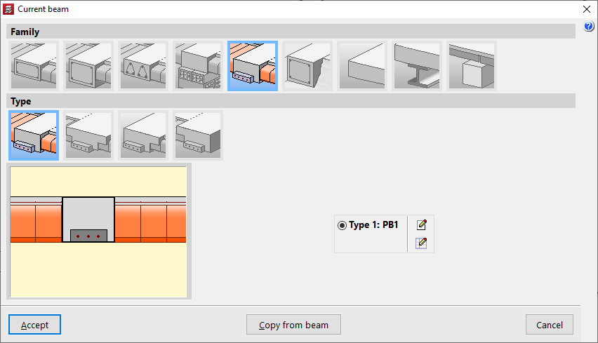
Prestressed beams
"Prestressed beams" have a prefabricated base and form their complete section during concreting together with the slab and the negative reinforcement placed in situ.
To define them, you need to edit the prestressed beam library by clicking on the corresponding button. Select "New", define the "Reference", the "Geometry", the characteristics of the "Materials", both for the concrete and the longitudinal reinforcement, and add the available "Section types".
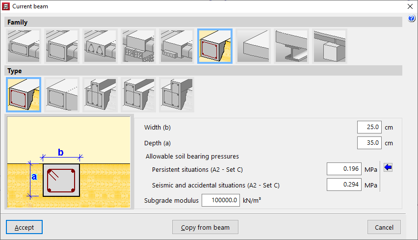
Foundation beams
"Foundation beams" are beams supported on the ground. To simulate the ground, elastic connections are automatically generated along the entire length of the foundation beam during the analysis process.
Among the available options are the following:
- Rectangular foundation beam
- Flat foundation beam
- Inverted T-shaped foundation beam
- Foundation beam with right-hand flange
- Foundation beam with left-hand flange
The value of the ballast modulus must be specified, as it will influence the stiffness of the elastic connections, as well as the "Allowable soil bearing pressures" in "Persistent situations" and "Seismic and accidental situations". You can "Import usual design values" for the permissible soil stresses using the button on the right.
In addition, the geometric properties of the beam are indicated, such as the "Width (b)", the "Depth (a)", if it is not a flat beam, and in the case of inverted T-beams or beams with flanges, the "Flap depth (s)" and the length of the "Left flap (i)" and the "Right flap (d)".
Non-structural or boundary hoop
A "non-structural or boundary hoop" is an element that contributes weight in the calculation (if it has width), but has no structural function. These elements are used to delimit the outline of floor slabs, especially two-way slabs or slabs.
Within this family, the following can be created:
- Non-structural or boundary hoop
This element allows you to represent a hoop with a certain "Width (b)".
- Non-structural hoop or zero width limit
This element has no width and is represented as a boundary line on the plan.
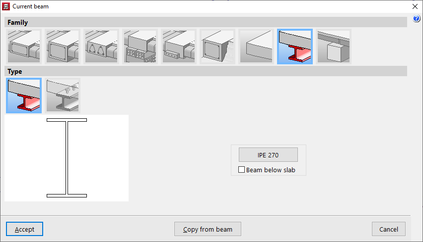
Steel beams
Within the "Steel beams" family, two types are available:
- Steel beam
This type corresponds to steel beams themselves. Only the metal section will be used in the calculation. If the "Beam under slab" box is checked, the weight of the concrete above the beam width will also be added. By clicking on the corresponding button on the right, you can access the "Section selection" panel, which allows you to choose from a variety of available sections, including beams with "Rolled steel section", "Reinforced rolled steel sheet section" and "Formed steel section".
- Composite beams
In this type, the concrete head works in conjunction with the metal profile. Therefore, in addition to selecting the "Section series" and the "Section", the "Connectors" must be defined, indicating their "Nominal diameter", the "Minimum length" and the connector head data ("Head thickness" and "Head diameter"), as well as its "Breaking stress".
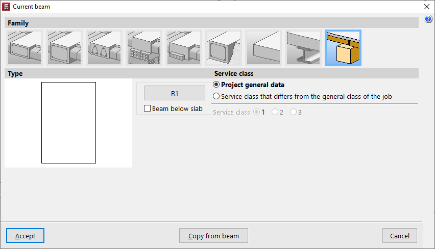
Timber beams
The "Timber beams" family allows the use of beams made from this material.
The geometry of the timber section is defined using the corresponding button, which opens the "Section selection" window.
The box "Beam under floor slab" allows you to indicate whether this is the case.
As for the "Service class", this may be the one defined in the "Project general data", but a "Service class that differs from the general class of the job" may also be applied.
Options in the "Sloped beams" menu (Beam input tab)
The "Sloped beams" option, within the "Beams" menu of the "Beam input" tab, allows you to enter sloped beams, concrete and steel, simple or diagonal bracing, hinged or fixed at the ends, as well as V-shaped bracing.
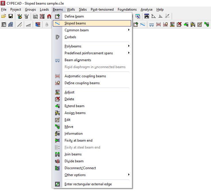
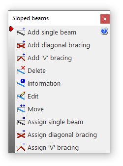
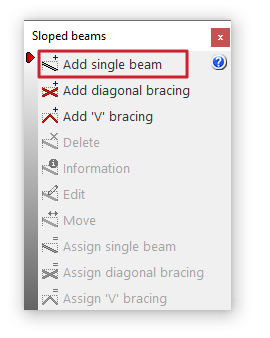
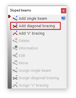
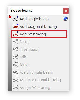
Clicking on this option opens the "Sloped beams" window, which includes a menu with different tools:
- Add single beam
- Add diagonal bracing
- Add 'V' bracing
- Delete
- Information
- Edit
- Move
- Assign single beam
- Assign diagonal bracing
- Assign 'V' bracing
Each of these features is explained below:
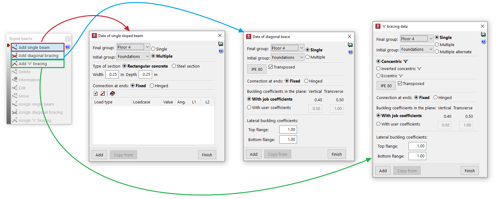
Add single beam / Add diagonal bracing / Add 'V' bracing
These options allow you to introduce these elements into the model:
- Add single beam
Insert a single inclined beam. - Add diagonal bracing
Insert a pair of diagonal braces. - Add 'V' bracing
Insert a pair of braces forming a V or an inverted V.
Inserting these elements enables the rest of the menu controls.
Delete
Allows you to delete a sloping beam, or a pair of diagonal bracing or V-bracing elements that have already been inserted. To do this, select them one by one using the left mouse button on the floor plan.
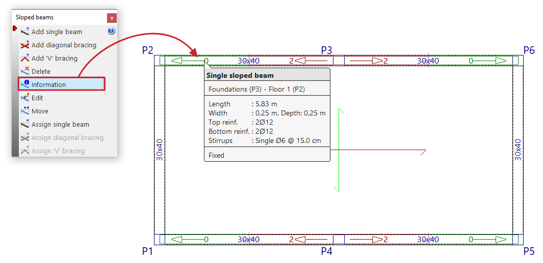
Information
Pressing this button provides information about the sloped beams, diagonal bracing or V-bracing already entered. To do this, select the element to be consulted on the floor plan with the left button or enter the corresponding element number.
An informative text box appears, displaying information such as the element's end and start group, its length, section, and the other parameters entered in its edit panel.
If the structure has been calculated, information on the reinforcement of simple inclined beams ("Upper reinforcement", "Lower reinforcement" and "Straddling") is also included.
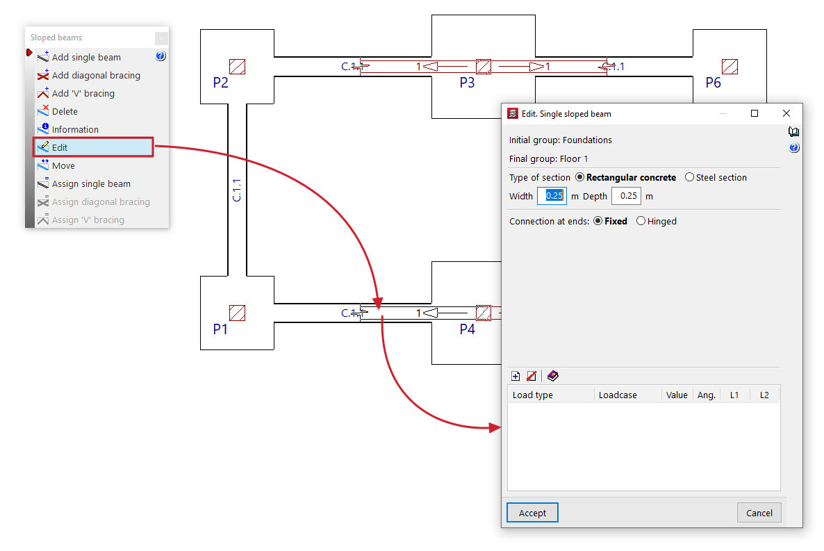
Edit
Allows you to select a sloping beam, diagonal bracing or V-shaped bracing already entered using the left mouse button on the floor plan and modify their parameters by reopening their editing window.
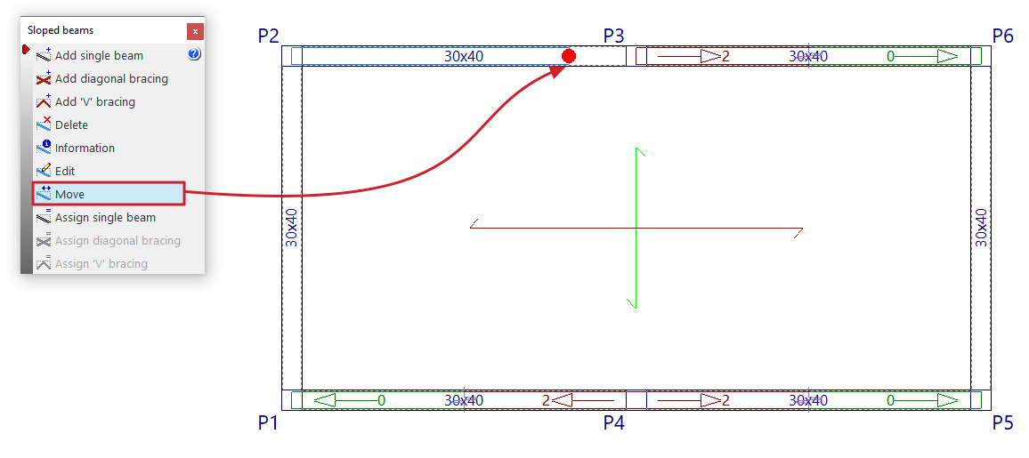
Move
Allows you to reposition the end of an inclined beam, a diagonal bracing member or a V-shaped bracing member that has already been entered, provided that a valid point is marked for its definition. This operation can be performed in the initial group or in the final group of the element.
| Note: |
|---|
| Editing or moving operations only affect the beam, diagonals, or bracing that are selected in the current floor plan, even if they were generated using the "Multiple" option when entering data. |
Assign single beam / Assign bracing diagonals / Assign V-bracing
These options allow you to change the data for simple sloped beams, diagonal bracing or V-bracing that has already been entered.
To do this, enter the new data in the edit panel that appears when you click on each option. You can obtain this data from any item using the "Copy from" button.
Then, by clicking on "Assign", you can select the elements on the floor plan to which you wish to assign the data, one by one, using the left mouse button.
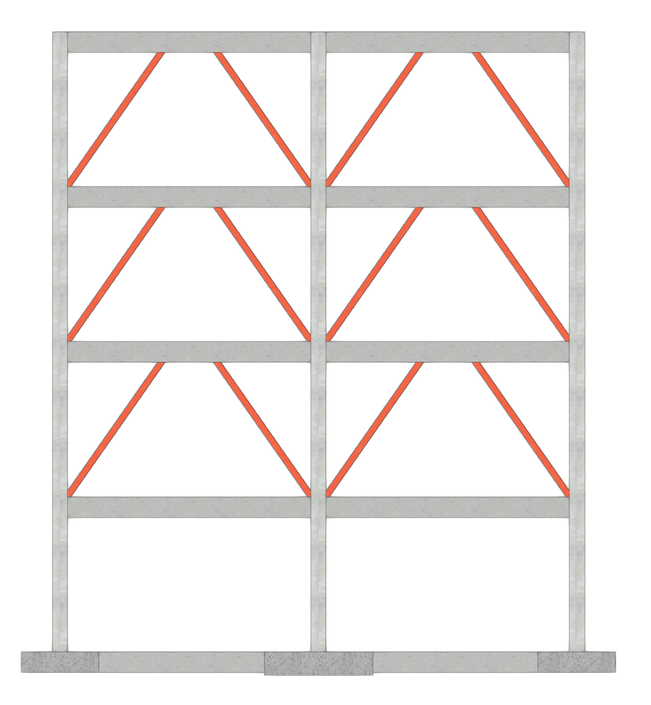
Inserting simple sloped beams
The "Add single beam" option allows for a single sloped beam from one point to another, either rectangular concrete or formed by a steel section.
This option is available in the "Sloped beams" menu that appears when you click on the option of the same name in the "Beams" menu, within the "Beam input" tab.
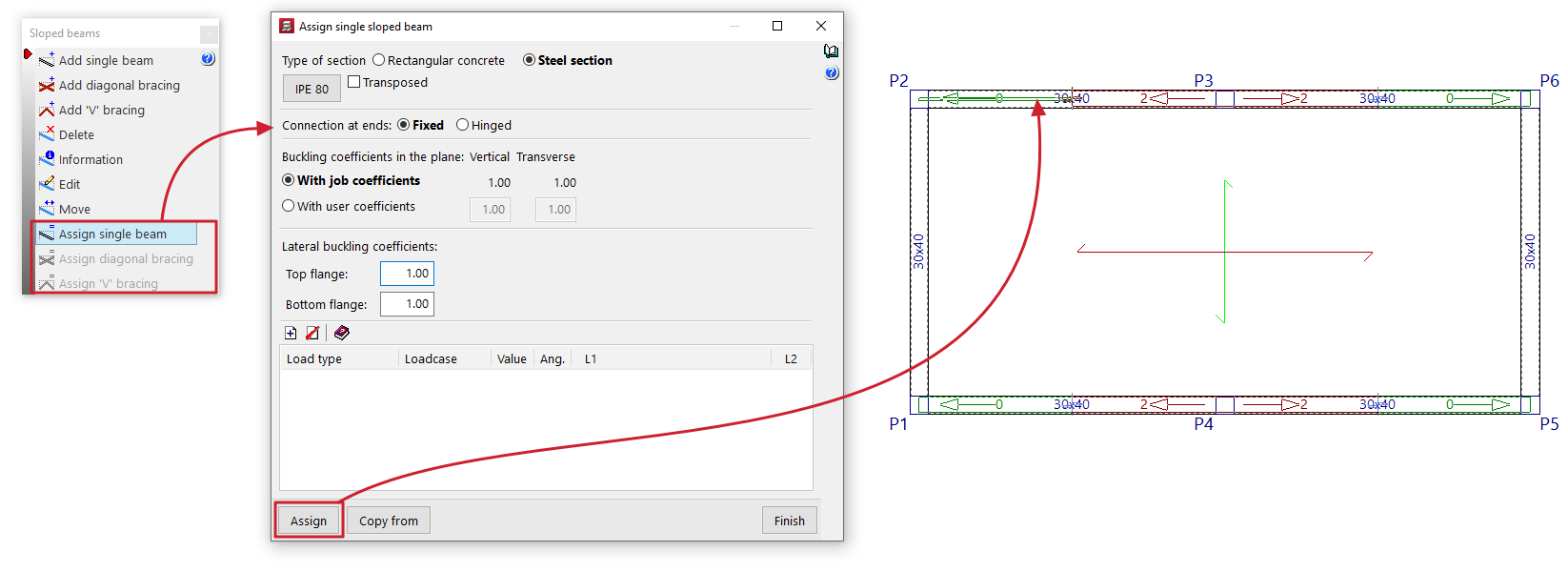
Data for the simple sloped beam
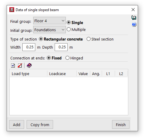
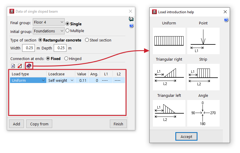
Clicking on the option opens the "Data of single sloped beam" window, where the following parameters are configured:
- Final group, Initial group
These drop-down menus are used to select the groups of floors where the sloped beam starts and ends. The program does not allow you to select groups in which a floor grouping has been defined, as it would not be able to determine on which floor the beam ends or begins. If this is the case, these floors must be ungrouped. On the other hand, it is possible to pass through several intermediate floor groups. - Single/Multiple
This option is only active if there is a group of plants between the selected final group and initial group, and allows you to select the input mode:- The "Simple" option allows you to insert a single sloped beam between the selected end group and initial group of floors.
- The "Multiple" option allows you to enter several sloped beams in several groups at once, located in the same position on the floor plan.
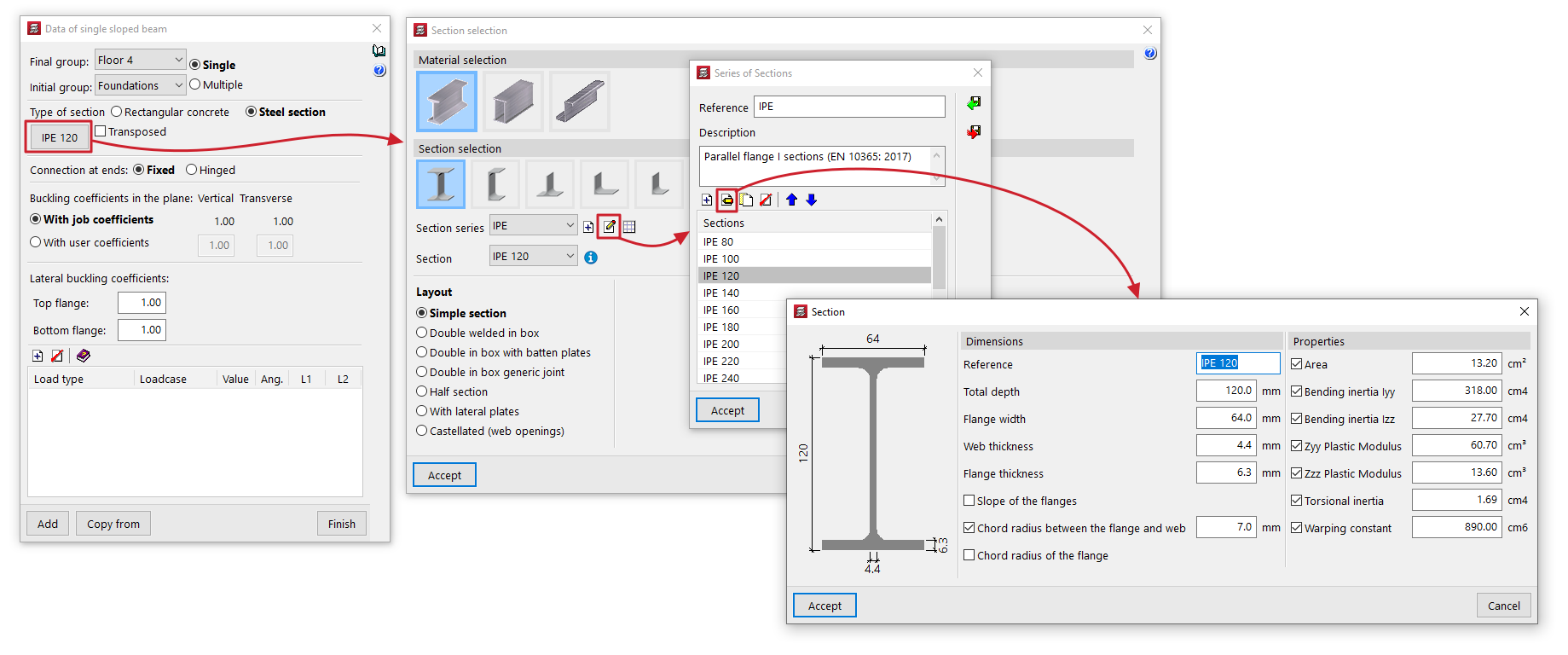
- Section type
Sloped beams can be made of "Rectangular concrete" or consist of a "Steel section". To do this, select the desired option from the selector.- Rectangular concrete
To define the section of the sloped rectangular concrete beams, enter the "Width" and "Depth" in the units indicated. - Steel section
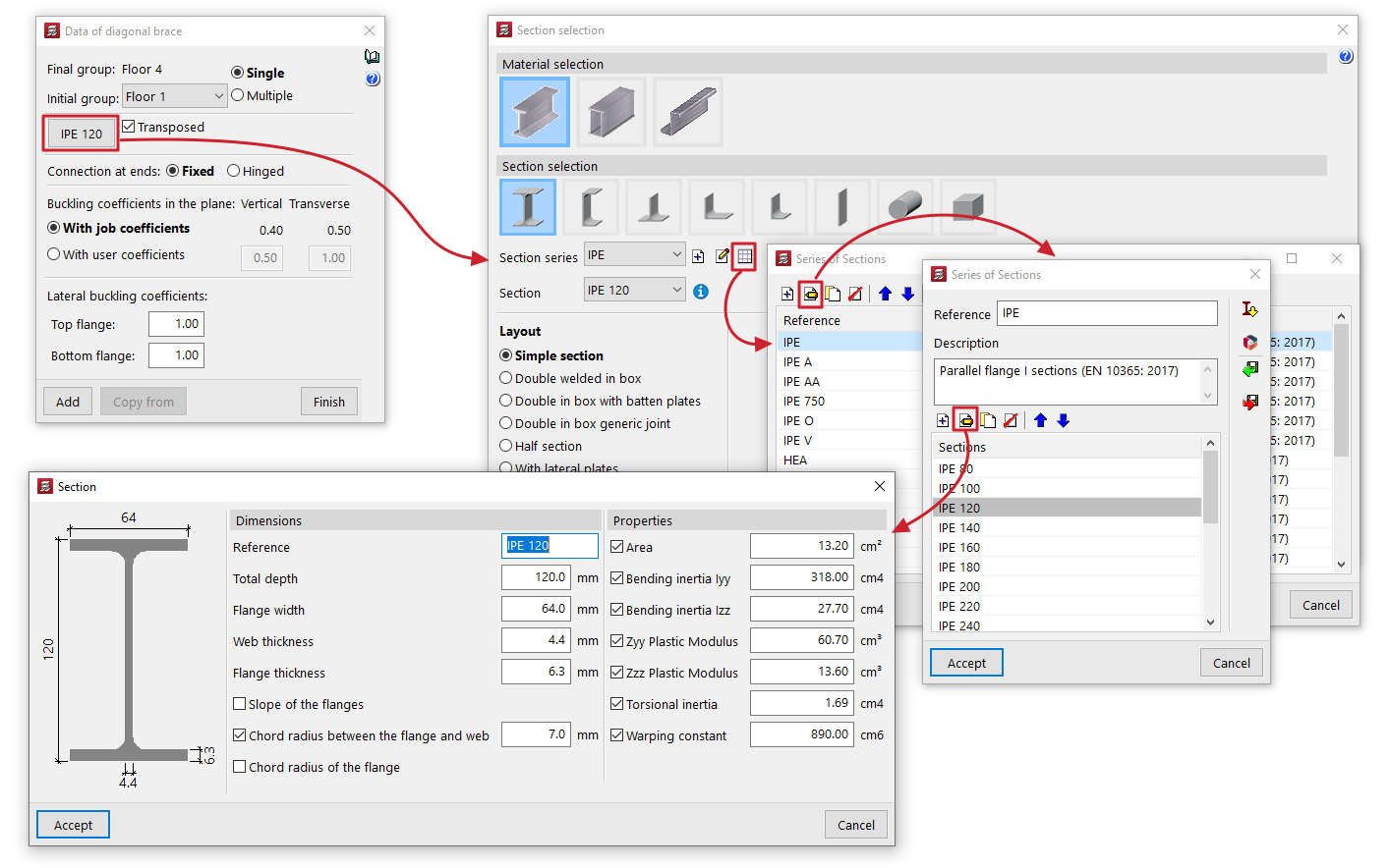
The options for defining the section of sloped steel section beams are as follows:- Material and section selection
The button on the left opens the "Section selection" window, where you can select the material and section of the steel section from those available, including rolled steel sections, reinforced rolled steel sheet sections, and shaped steel sections. - Transposed
The "Transposed" box allows you to rotate the section 90º counterclockwise.
- Material and section selection
- Rectangular concrete
- Connection at the ends
It can be defined as "Bi-potentiometer" or "Bi-articulated". - Buckling coefficients in the vertical and transverse planes
This section allows you to define the buckling coefficients in the "Vertical" and "Transverse" planes of sloped steel section beams. You can select "With project coefficients" (as indicated in "Project > Beam options > Buckling coefficients for sloped steel beams and bracing") or "With own coefficients", in which case the user must enter them. - Lateral buckling coefficients
This section allows you to enter the lateral buckling coefficients in the "Upper flange" and "Lower flange" of the sloped steel section beams.
| Note: |
|---|
| In the case of sloped steel beams, in order to obtain the buckling length of each sloped beam, it is assumed that the buckling coefficients requested multiply the length between the extreme nodes of the beam, even in the case where two sloped beams entered by the user appear to intersect at a point, since the program does not generate such an intersection. The vertical and transverse buckling coefficients are established, respectively, in a vertical plane containing the bar and the Z-axis of the structure, and in the transverse plane to it, and not according to the local axes of the bar. |
Loads on the sloped beam
Next, the program displays a table where you can "Add" or "Delete" loads on the sloped beam. The following parameters must be specified for each load:
- Load type
Allows you to specify a load type. This can be "Uniform", "Point load", "Strip load", "Right triangular load" or "Left triangular load". Selecting each of these loads requires the subsequent entry of the parameters that define them. The help button at the top of the table displays a series of diagrams for each type of load that describe these parameters. - Loadcase
Allows you to assign the simple hypothesis to which the load will be associated. - Value
Allows you to indicate the value of the load. You can view the units in which the load value should be defined by hovering the pointer over the column heading. - Ang.
Allows you to define the angle formed by the load with the vertical axis of the structure. As a reference, a load with an angle of 0º indicates that it has the direction and sense of gravity; a load with an angle of 90º indicates that it is horizontal and has the same sense as the order of introduction of the beam you are going to introduce on screen. - L1, L2
These parameters allow you to define the points of application at the origin and end of strip or triangular loads, as well as the point of application of point loads. This distance is measured in true magnitude, i.e. along the beam and not as a horizontal projection from its origin.
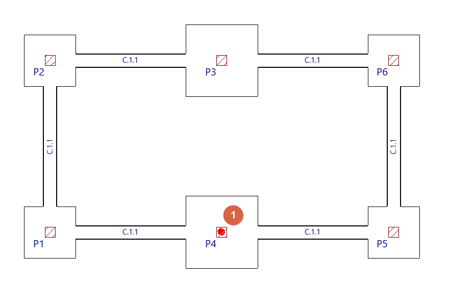
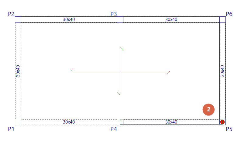
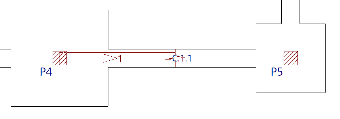
Inserting the sloped beam in plan view
To insert a sloped beam, use the left mouse button to mark the starting point of the beam in the initial group. The program will then automatically move to the final group, where you can indicate the end point of the beam. The sloped beam can have a pillar or a horizontal beam as its starting and/or end point.
Inserting diagonal bracing
The "Add diagonal bracing" option allows you to enter pairs of diagonal bracing between two points on the floor plan formed by steel sections.
This option is available in the "Sloped beams" menu that appears when you click on the option of the same name in the "Beams" menu, within the "Beam input" tab.
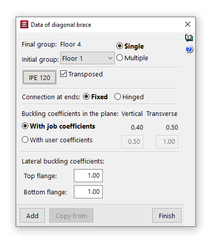
Diagonal bracing data
Clicking on the option opens the "Diagonal bracing data" window, where the following parameters are configured:
- Final group, Initial group
In the drop-down menus "Final group" and "Initial group", select the groups of floors where the diagonal bracing start and end. The program does not allow you to select groups in which a group of floors has been defined, as it would not be able to determine on which floor the diagonals end or start. If this is the case, these floors must be ungrouped. On the other hand, it is possible to pass through several intermediate groups of floors. - Single/Multiple
This option is only active if there is a group of plants between the selected final group and initial group, and allows you to select the input mode:- The "Simple" option allows you to enter a single pair of diagonal bracing between the selected end group and initial group of floors.
- The "Multiple" option allows you to enter several pairs of diagonal bracing elements in several groups at once, located in the same position on the floor plan.
- Material and section selection
The button on the left opens the "Section selection" window, where you can select the material and section of the steel section from those available, including rolled steel sections, reinforced rolled steel sheet sections, and shaped steel sections.- Transposed
The "Transposed" box allows you to rotate the steel sections 90º counterclockwise.
- Transposed
- Connection at the ends
This can be defined as "Bi-potentiometer" or "Bi-articulated". - Buckling coefficients in the vertical and transverse planes
This section allows you to define the buckling coefficients in the "Vertical" and "Transverse" planes of the sections that form the diagonal bracing. You can select "With project coefficients" (as indicated in "Project > Beam options > Buckling coefficients for sloped steel beams and bracing") or "With own coefficients", in which case the user must enter them. - Lateral buckling coefficients
This section allows you to enter the lateral buckling coefficients in the "Top flange" and "Bottom flange" of the sections that form the diagonal bracing.
| Note: |
|---|
| In the case of steel diagonal bracing, to obtain the buckling length of each diagonal bracing, it is considered that the buckling coefficients requested multiply the length between the extreme nodes of the diagonal, i.e. the intermediate node generated by the program at the intersection of bars is not taken into account for this purpose. The vertical and transverse buckling coefficients are established, respectively, in a vertical plane containing the bar and the Z-axis of the structure, and in the transverse plane to this, and not according to the local axes of the bar. |
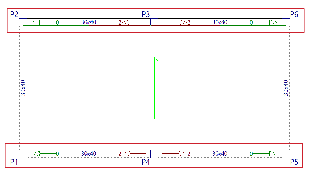
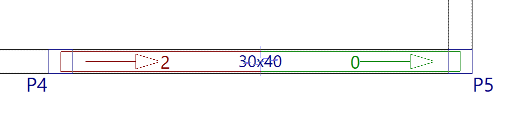
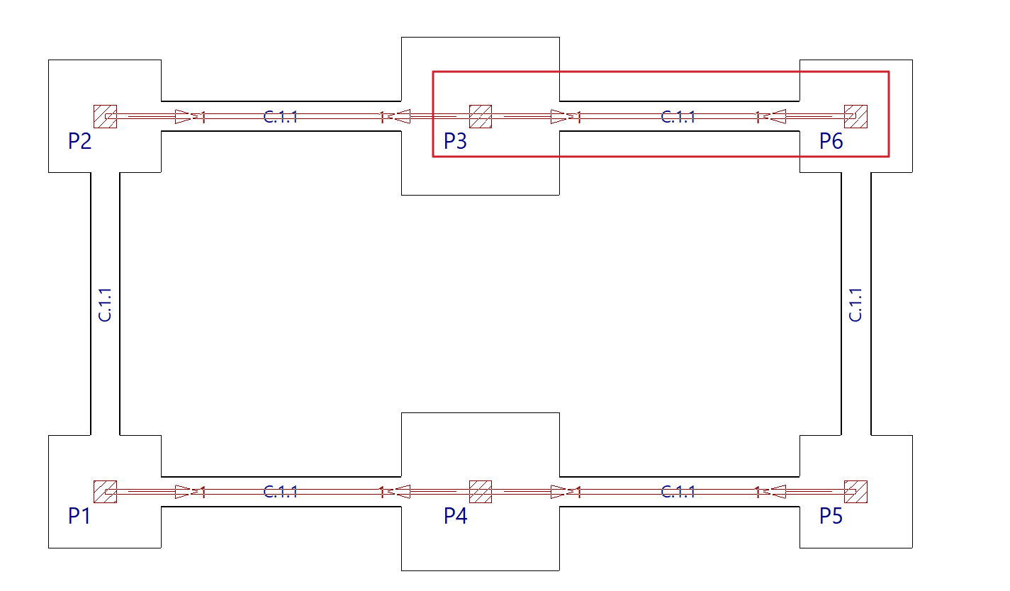
Introduction of diagonal bracing in floor plans
To insert the diagonal bracing, use the left mouse button to mark the starting points of each of the diagonals in the initial group.
Diagonal bracing can have a column as its starting point, so the bases of the columns must be marked in the initial group of diagonals.
| Nota: |
|---|
| At the intersection of the diagonal bracing, the program will generate a rigid node. The diagonals are dimensioned for both tension and compression. Therefore, they may present slenderness problems, as it will be checked that the maximum slenderness defined in the corresponding regulations for elements subjected to compression is not exceeded. |
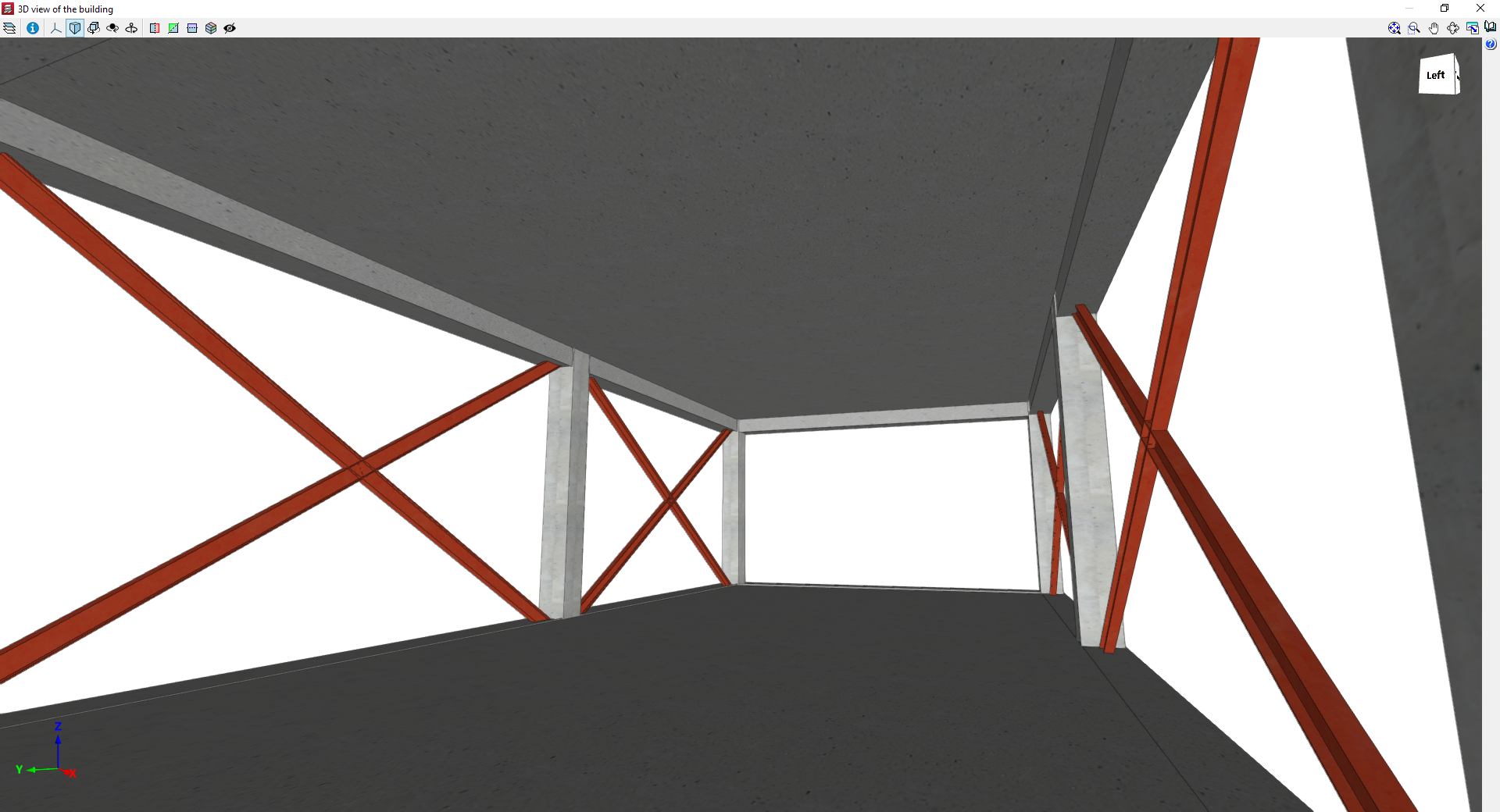
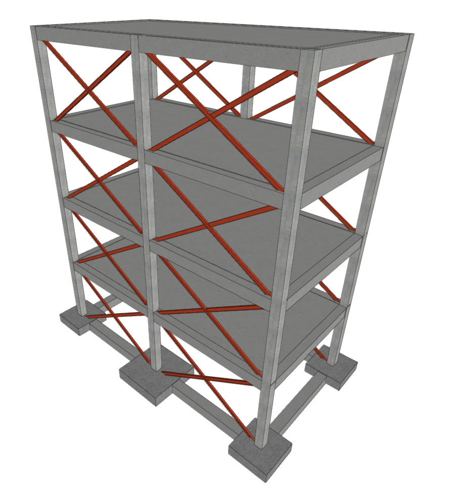
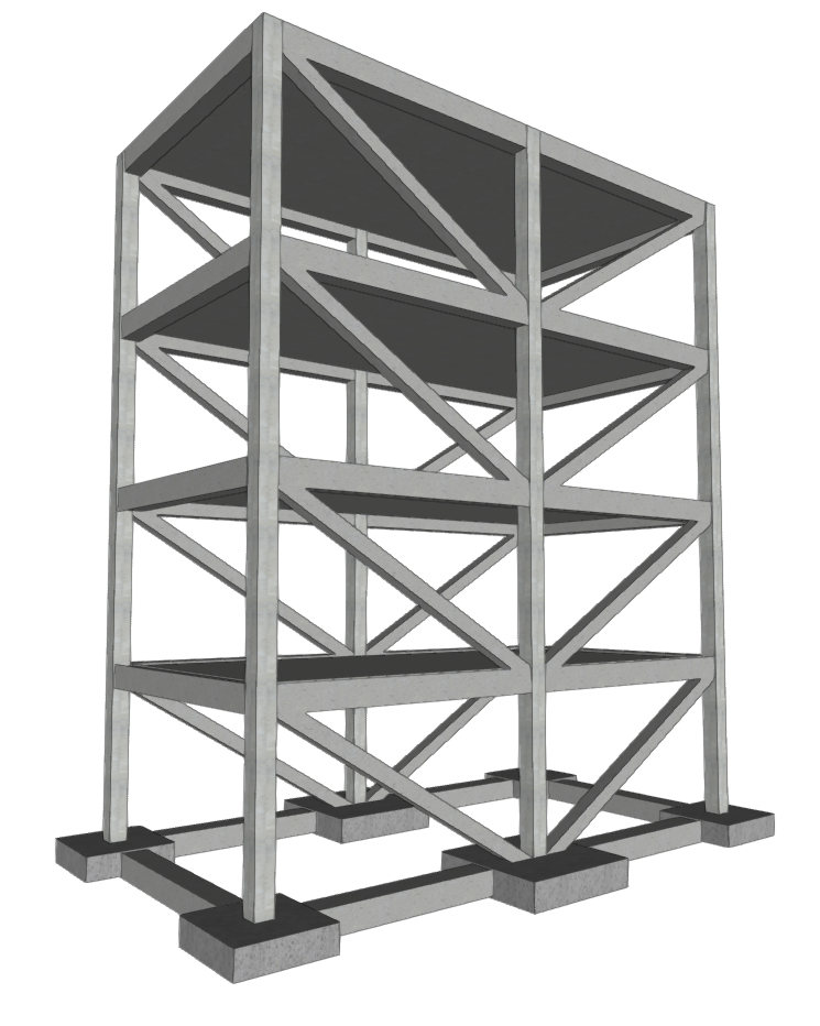
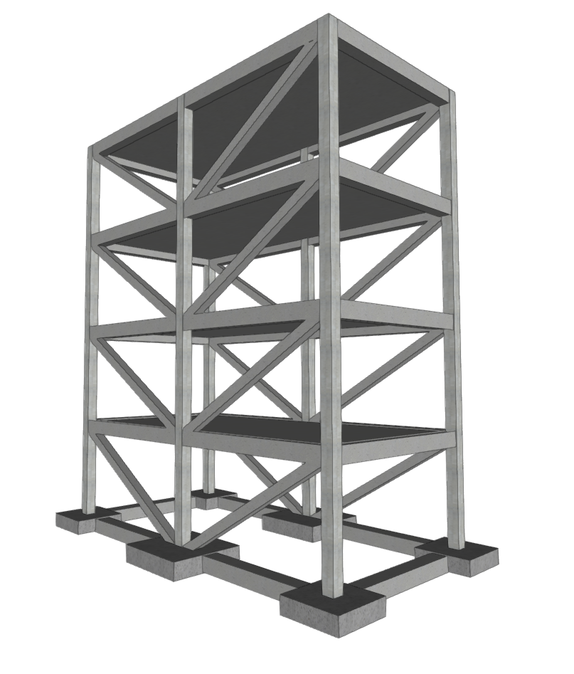
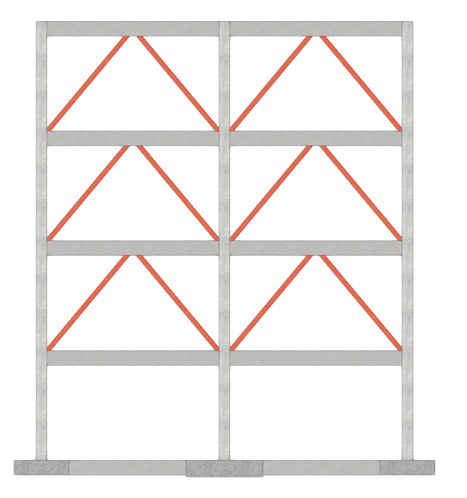
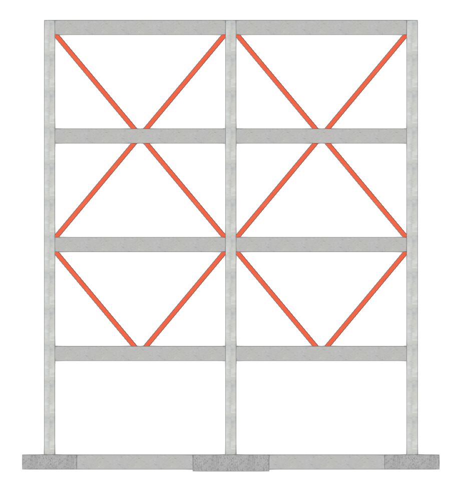
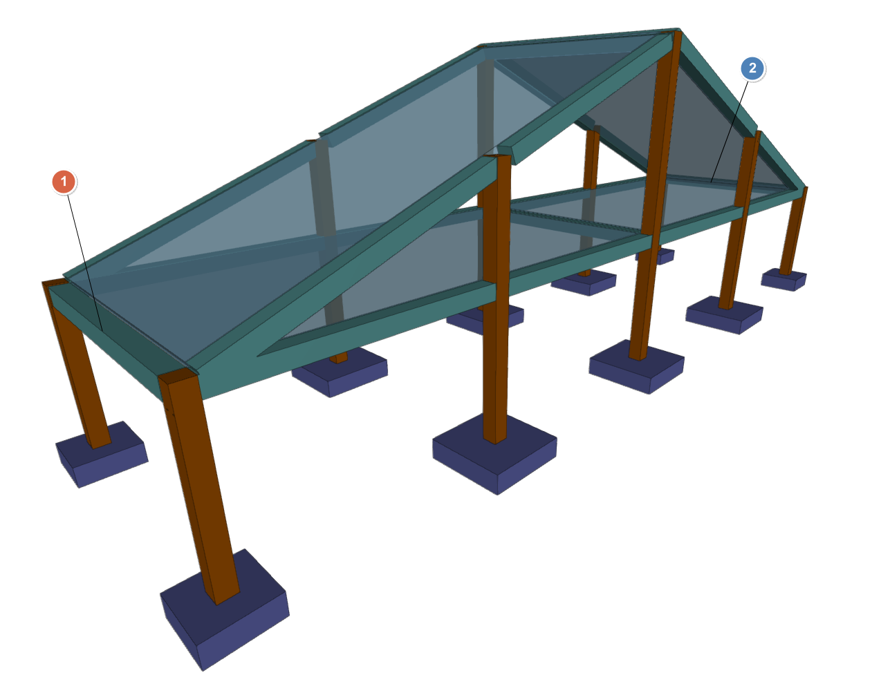
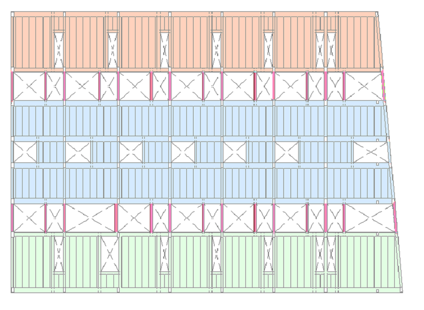
3D views of a model with diagonal bracing
Inserting 'V' bracing
The "Add 'V' bracing" option allows you to insert pairs of V-shaped or inverted V-shaped bracing between two points on the floor plan, formed by steel sections.
This option is available in the "Sloped beams" menu that appears when you click on the option of the same name in the "Beams" menu, within the "Beam input" tab.
Data on V-shaped bracing
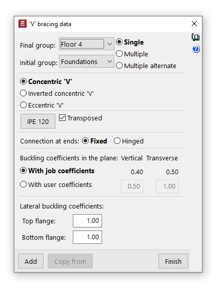
Clicking on the option opens the "V-brace data" window, where the following parameters are configured:
- Final group, Initial group
In the drop-down menus "Final group" and "Initial group", select the groups of plants where the bracing starts and ends. The programme does not allow you to select groups in which a grouping of floors has been defined, as it would not be able to determine on which floor the bracing ends or begins. If this is the case, these floors must be ungrouped. On the other hand, it is possible to pass through several intermediate groups of floors. - Single/Multiple
This option is only active if there is a group of plants between the selected final group and initial group, and allows you to select the input mode:- The "Simple" option allows you to enter a single pair of bracing between the selected end group and start group of floors.
- The "Multiple" option allows you to enter several pairs of bracing in several groups at once, located in the same position on the floor plan. This option is only active if there is a group of floors between the selected end group and the selected start group.
- The "Multiple alternate" option allows you to enter pairs of bracing in several groups at once, alternating their orientation on each floor.
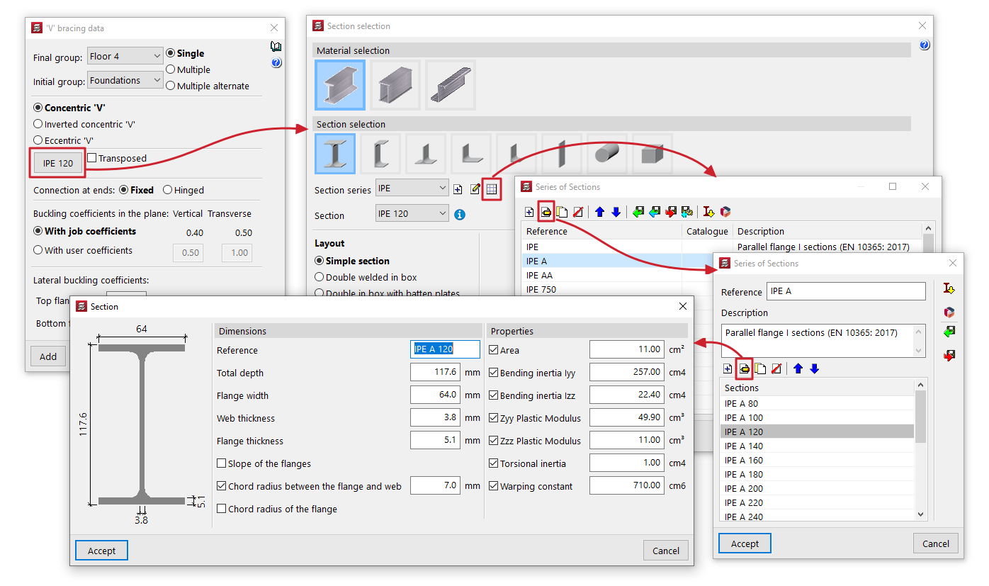
- Material and section selection
The button on the left opens the "Section selection" window, where you can select the material and section of the steel section from those available, including rolled steel sections, reinforced rolled steel sheet sections, and shaped steel sections.- Transposed
The "Transposed" box allows you to rotate the steel section 90º counterclockwise.
- Transposed
- 'V' type bracing
- Concentric V'
Allows you to insert two braces forming a V shape that meet at the central point in the initial group. - Inverted concentric 'V'
Allows two braces to be inserted, forming an inverted V that joins at the central point in the end group. - Eccentric 'V'
Allows you to enter two bracings forming an inverted V and separated by the distance marked in the "Link length" field. This option is only available for "Single" or "Multiple" bracings.
- Concentric V'
- Connection at ends
This can be defined as "Fixed" or "Hinged". - Buckling coefficients in the vertical and transverse planes
This section allows you to define the buckling coefficients in the "Vertical" and "Transverse" planes of the sections that form the bracing. You can select "With project coefficients" (as indicated in "Project > Beam options > Buckling coefficients for sloped steel beams and bracing") or "With own coefficients", in which case the user must enter them. - Lateral buckling coefficients
This section allows you to enter the lateral buckling coefficients in the "Top flange" and "Bottom flange" of the sections that form the bracing.
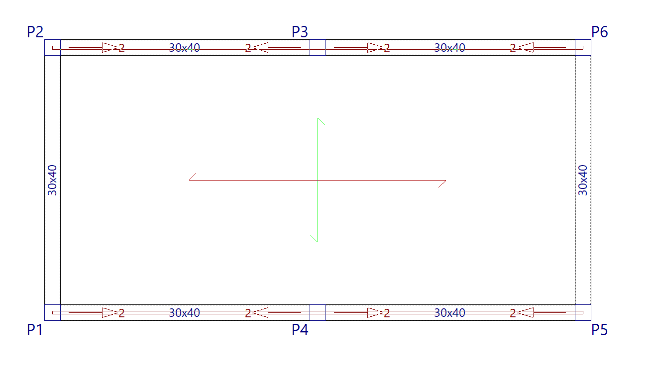
Inserting V-shaped bracing in the floor plan
To insert V-bracing, mark their starting points or their projection in the initial group with the left button. A V-brace can have a column or a horizontal beam as its starting point.
At the central point, the V-shaped bracing must also meet a pillar or horizontal beam, either in its initial group or in its final group, depending on the type chosen.

"Common beam" option
A common beam is a beam that, when inserted into one group of floors, is also visible in another group, meaning it can be used as a floor edge beam in both groups.
This can be useful, for example, to define an eave beam common to the floor slab under the roof and the floor slab that forms the roof slope, or to a beam between a horizontal floor slab and a floor slab that forms a staircase or garage ramp slab.
The "Common beam" option in the "Beams" menu of the "Beam input" tab allows you to define a beam common to two groups of floors. Selecting it displays a menu with two tools:
- Make a common beam
- Undo common beam
Each of these features is detailed below.
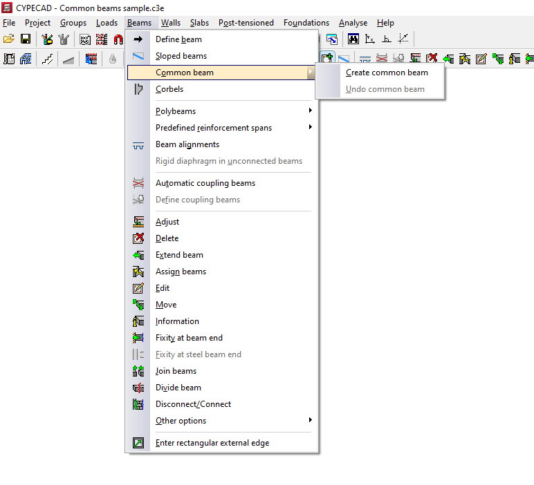
Create common beam
The "Create common beam" option allows you to define a common beam.
The process for inserting a common beam is as follows:
- Firstly, the beam must be inserted into only one of the groups (or the original group) using the "Insert beam" option, also in the "Beams" menu.
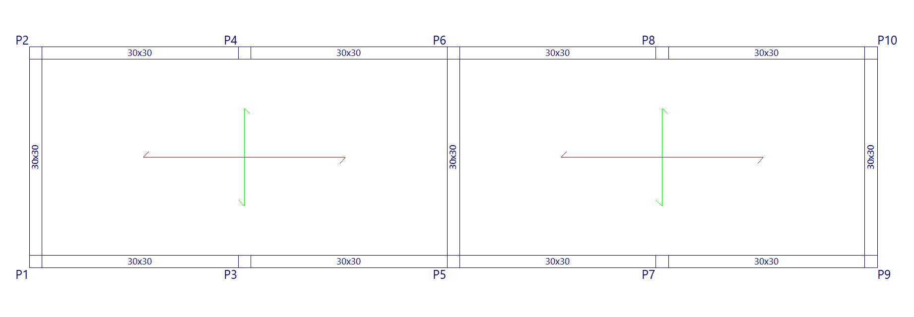
- In the group of destination floors where you wish to generate the common beam, there must be sufficient space available for the beam to be generated correctly and not overlap with other elements.
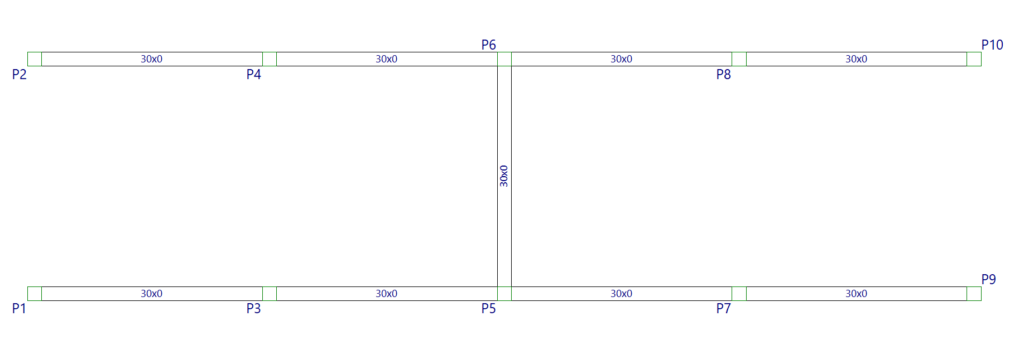
- Next, use the "Make common beam" option and click on the beam already entered in the original group.
You can select the central part of the beam to make a common beam along its entire length, or select one end or the other of the beam to make a common beam only half its length: each half can be common with different groups.
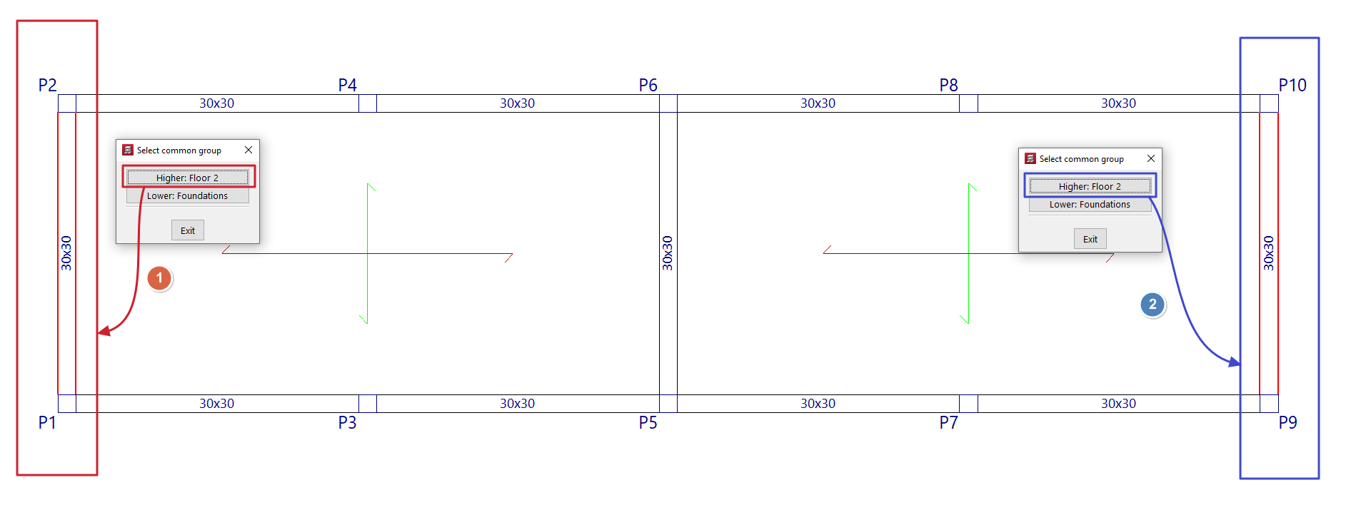
At this point, the program will display the following message: "Select common group". The target floor group must be selected from those available in the pop-up window.
- After doing so, the beam will also be visible in that group of floors, and can be used as part of the definition of the contour of floor slabs in both groups. The axis of this type of beam is drawn with a dotted line.
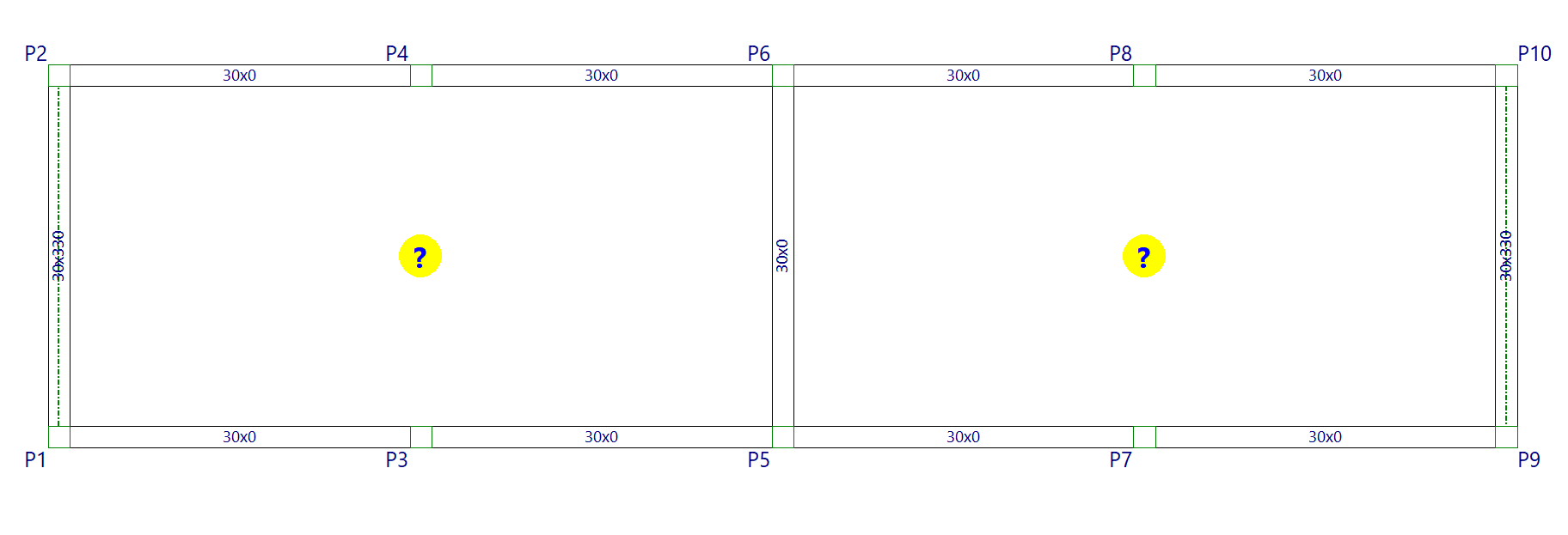
- From here, the model is completed by inserting the necessary floor slabs, as well as the slopes of the slabs.
The reinforcement and stress envelopes for common beams should be consulted in the group where the beam was originally inserted.
Undo common beam
The "Undo common beam" option allows you to split a beam associated with a common beam.
This operation must be performed on the associated beam and not on the original beam, i.e. on the beam visible in the target group selected when using the "Common beam" option.
By doing so, you will obtain two independent beams, one in each group of floors.
| Note: |
|---|
| To delete a common beam using the "Delete" option in the "Beams" menu, you must first delete the associated beam in the target group. Then you can delete the original beam. |
Polybeams
The "Polybeams" menu, within the "Beams" menu of the "Beam input" tab or the "Results" tab, allows you to create and manage polybeams.
A polybeam is a set of consecutive beams without intermediate columns that constitute a group for the purposes of editing their section or removing them.
Thus, any geometric change (for example, from "Beams > Edit") made to one of the beams is applied to all the beams that form the polybeams.
Similarly, deleting the polybeam (using "Beams > Delete") causes the entire set of beams that constitute it to be deleted. However, the reinforcement of each beam in the set may be different.
The menu offers the following options:
Compose
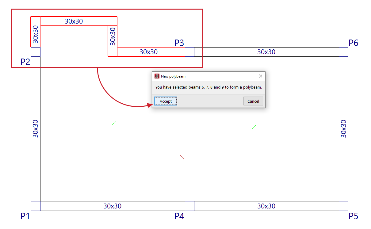
The "Compose" option allows you to create a new composite beam. To do this, select consecutive beam sections with the left mouse button and, when finished, confirm the operation with the right mouse button. The program will notify you of the beams that have been selected in a pop-up window, indicating their reference on the screen. When you accept this notification, the composite beam is created.
Break down
The "Break down" option allows you to ungroup all the beams of one or more previously created polybeams. To do this, select the polybeams to be broken down with the left mouse button or mark a capture area on the screen.
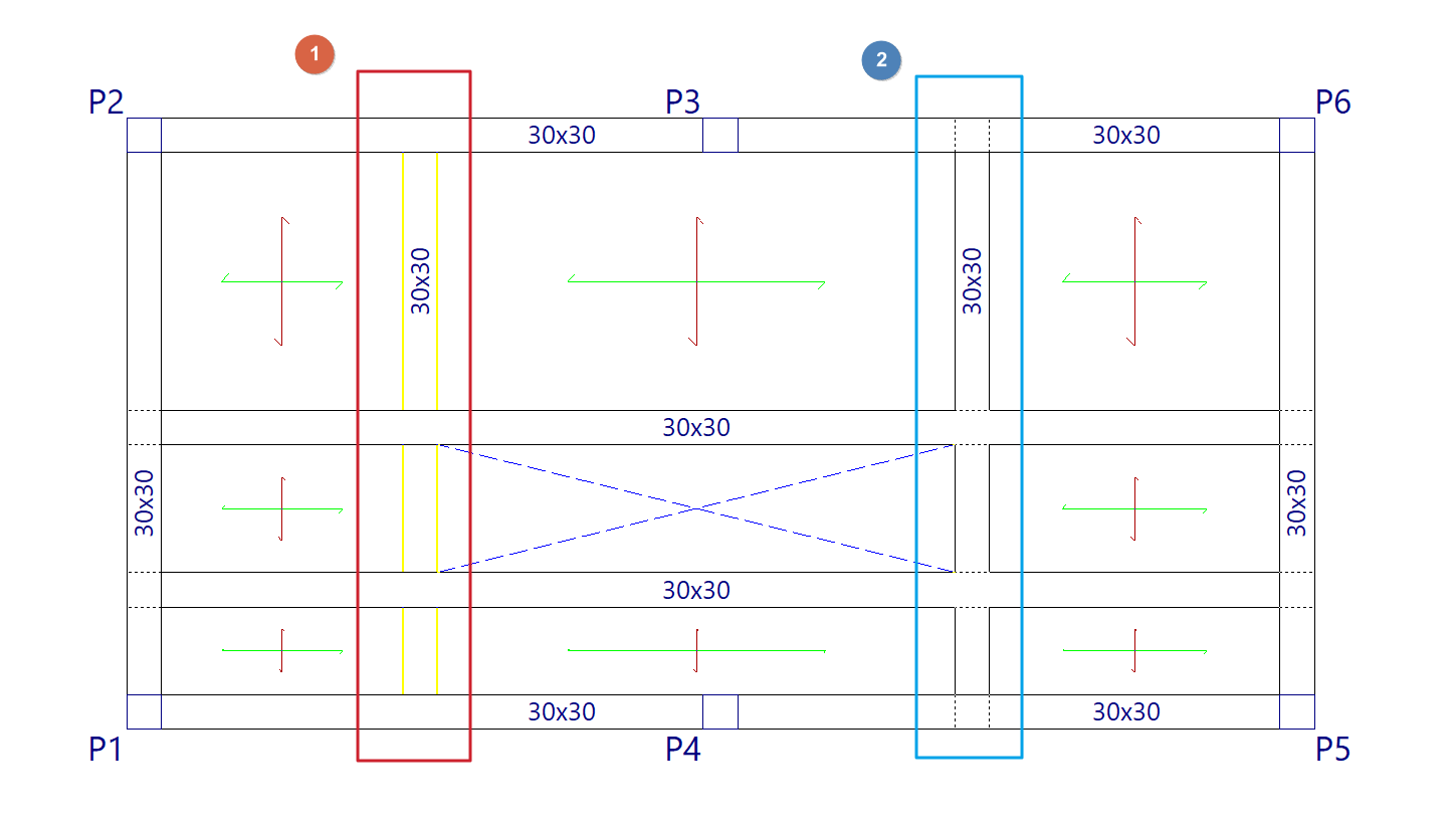
Add beams to a polybeam
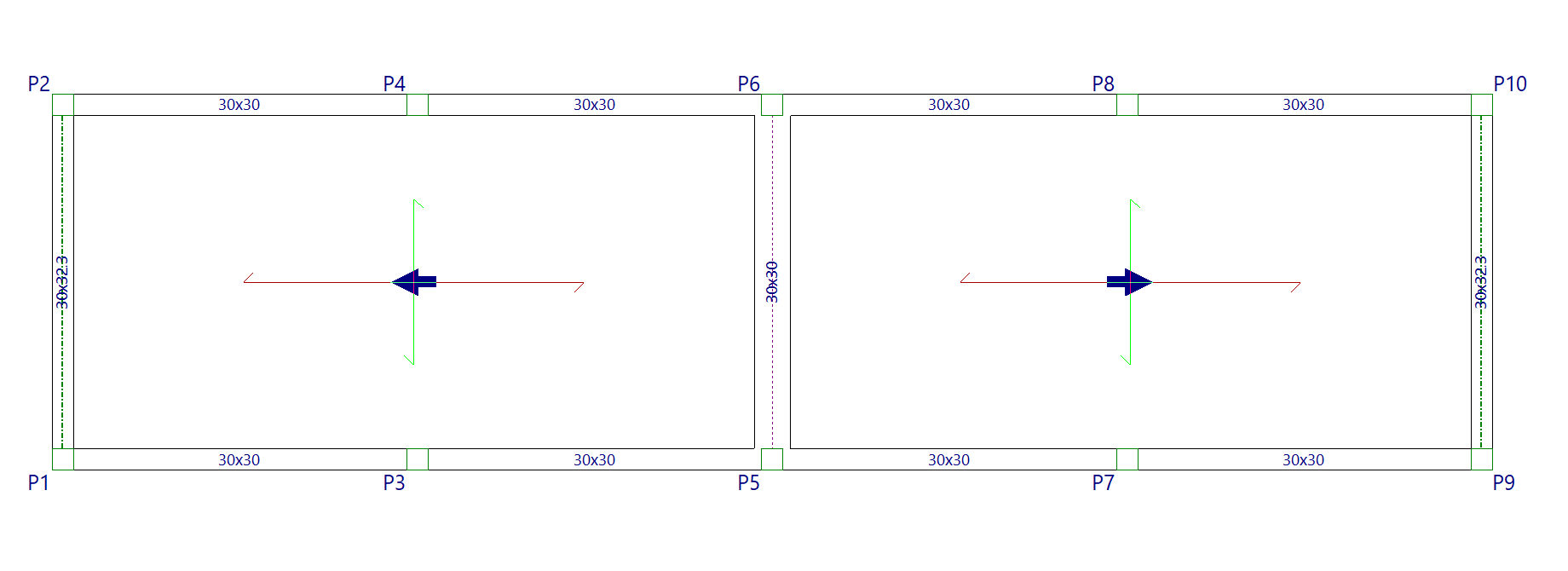
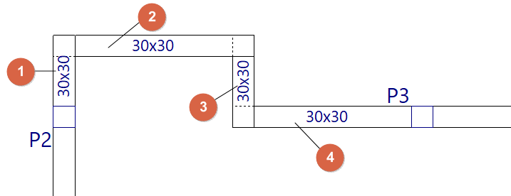
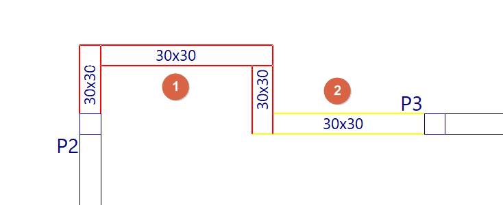
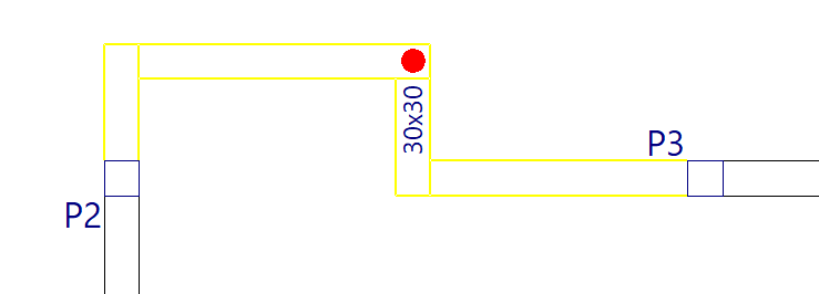
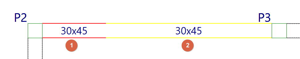
The "Add beams to a polybeam" option allows you to add one or more beams to an existing polybeam. To do this, select the polybeam (1) and then the beam or beams you want to add to it (2), confirming the operation with the right mouse button. The program will notify you of the beams that will be added to the polybeam, indicating their reference on the screen. When you accept the notification, the polybeam is updated with the addition of the selected beams.
Divide
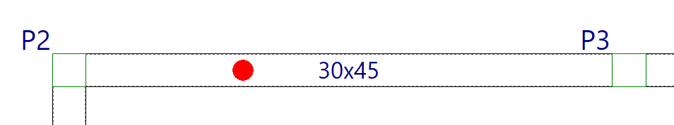
The "Divide" option allows you to split a polybeam into several polybeams or into separate beams at the point selected with the left mouse button. This option can also be useful for ungrouping one of the two end beams of a polybeam.
Predefined reinforcement spans in beams
The "Predefined reinforcement spans" menu, within the "Beams" menu of the "Beam input" tab or the "Results" tab, allows you to create or delete predefined reinforcement sections in multi-beams.
A predefined reinforcement section in the set of beams that make up a composite beam is one in which the positive and negative reinforcement is continuous.
| Note: |
|---|
| This will be possible provided that the analysed length of the steel bar does not exceed the "Maximum length of a bar" set in the general options of the program. |
The menu offers the following options:
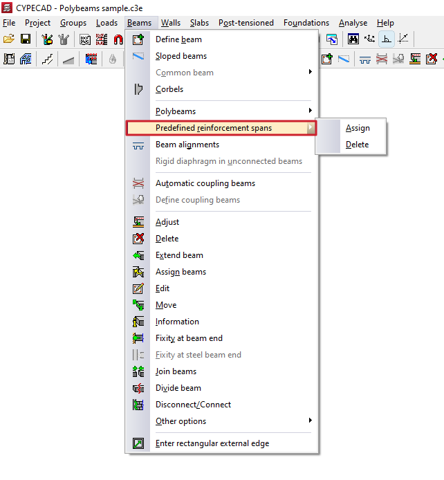
Assign
The "Assign" option allows you to create a predefined reinforcement section in each of the multi-beams that are subsequently selected, either with the left button or by means of a capture area.
Each poliviga selected in this way constitutes an independent, predefined reinforcement section.
In this way, when analysing and assembling the frames, the program will apply continuous reinforcement to each predefined reinforcement section created.
Delete
The "Delete" option allows you to ungroup the reinforcement of all beams in a predefined reinforcement section created previously. After using this option, you will need to re-analyse or re-reinforce the frames to generate the reinforcement of the beams independently.
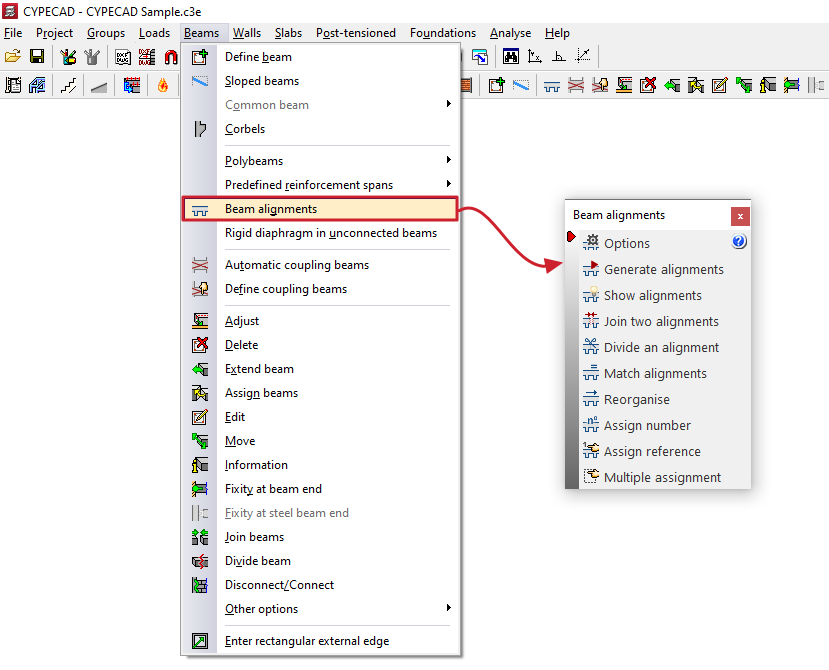
Beam alignments
The "Beam alignments" option in the "Beams" menu of the "Beam input" tab opens a dialogue box with a series of options that allow you to generate, view and modify beam alignments.
Beam alignments are sets of consecutive beams that the program references and attempts to assemble as a single continuous frame.
The following tools are available:
- Options
- Generate alignments
- Show alignments
- Join two alignments
- Divide an alignment
- Match alignments
- Reorganise
- Assign number
- Assign reference
- Multiple assignment
Each of these features is detailed below:
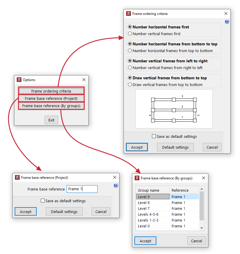
Options
The following tools are grouped under "Options":
- Frame ordering criteria
Allows you to configure the frame ordering criteria when generating alignments by choosing one of the following options:- Number horizontal frames first / Number vertical frames first
- Number horizontal frames from bottom to top / Number horizontal frames from top to bottom
- Number vertical frames from left to right / Number vertical frames from right to left
- Draw vertical frames from bottom to top / Draw vertical frames from top to bottom
- Frame base reference (Project)
Allows you to enter the base reference for frames for the entire project. - Frame base reference (by group)
Allows you to enter the base reference for the frames in each of the groups in the project.
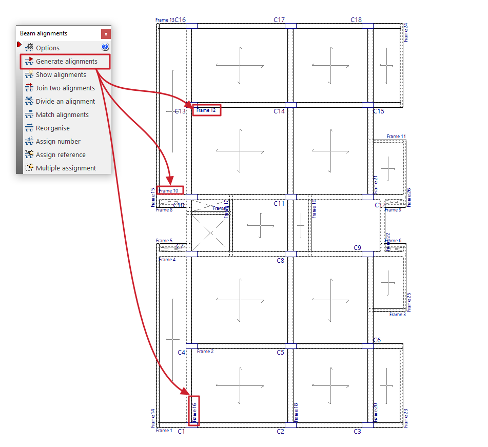
Generate alignments
Before the analysis, the program automatically creates the beam alignments.
If the user wishes to reorder the frames, divide, join or match alignments, the "Generate alignments" option must be executed beforehand in order to have a starting point from which to make the desired modifications.
| Note: |
|---|
| If there is an angle difference between two beams greater than the value indicated in "Project > General data > By position > Options for beams > Beam angle for alignment" (default, 35º), the program generates two different alignments and, therefore, the reinforcement is divided. |
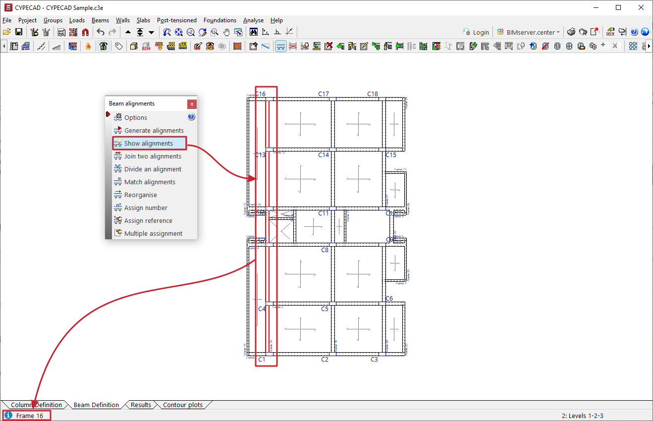
Show alignments
The "Show alignments" option allows you to check the numbering of the alignment or portal to which the selected beam belongs.
To do this, after selecting the option, click on a beam with the left mouse button. The program will display information about the frame to which it belongs in the message line at the bottom of the general program interface.
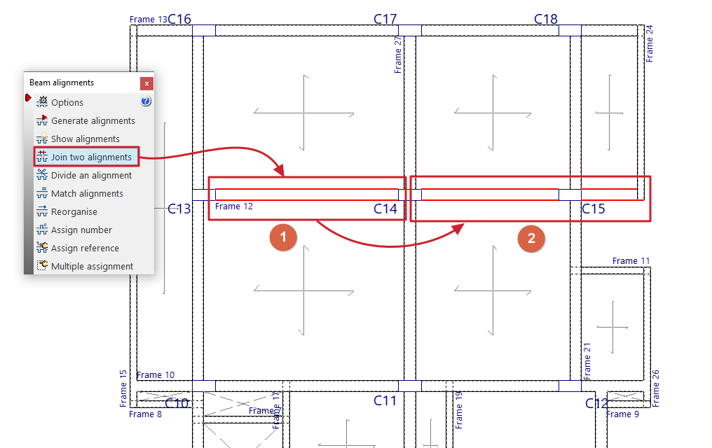
Join two alignments
The "Merge two alignments" option allows you to select two consecutive alignments and create a single alignment from them.
In this way, the program will arrange a continuous assembly in the resulting alignment.
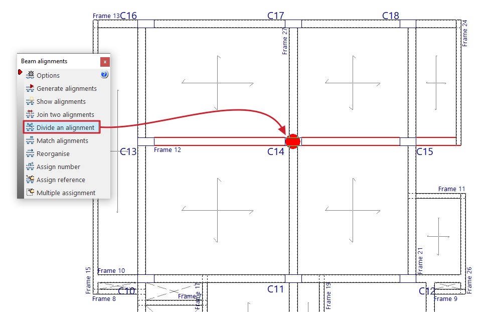
Divide an alignment
The "Divide an alignment" option allows you to select a column from an alignment and split it into two alignments at that point. The reinforcement at that point is split, which does not imply that the continuity between beams is lost.
| Note: |
|---|
| If any changes are made to the beams (adding new beams, removing beams, etc.) after generating alignments, joining or splitting them, the alignments are automatically regenerated. The way in which the alignments are made does not influence the stress analysis. The only difference is that the reinforcement will be continuous or divided. If, after analysing, you run "Generate alignments", "Join two alignments" or "Divide an alignment", the analysis data for that floor will be lost. It is therefore advisable to perform these operations before analysing. |
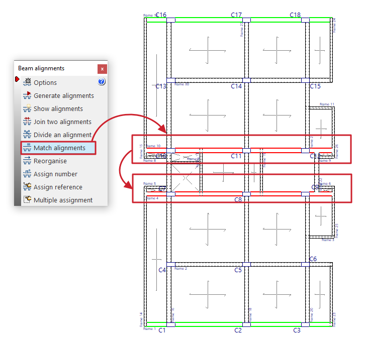
Match alignments
The "Match alignments" option allows you to select two or more alignments before analysis so that the program applies the same reinforcement to them during analysis.
To do this, select the alignments to be matched with the left button and press the right button to finalise the selection.
Alignments that are already matched are highlighted in green when this option is enabled.
| Note: |
|---|
| The alignments to be matched must contain the same number of spans or sections, and their matching spans must contain the same number of bars. |
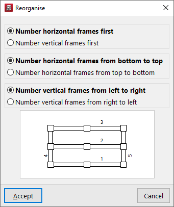
Reorganise
The "Reorder" option allows you to regenerate the references of the alignments or frames according to their position on the plan.
When you click on the option, a window appears where you can configure the following reordering criteria:
- Number horizontal frames first / Number vertical frames first
- Number horizontal frames from bottom to top / Number horizontal frames from top to bottom
- Number vertical frames from left to right / Number vertical frames from right to left
Upon accepting the dialogue box, the program will renumber the frames according to the selected criteria.
| Note: |
|---|
| It is not possible to reorder beam alignments if the reference of any of them has been modified using the "Assign reference" option. In this case, these references can be deleted using the same option and leaving the reference blank. |
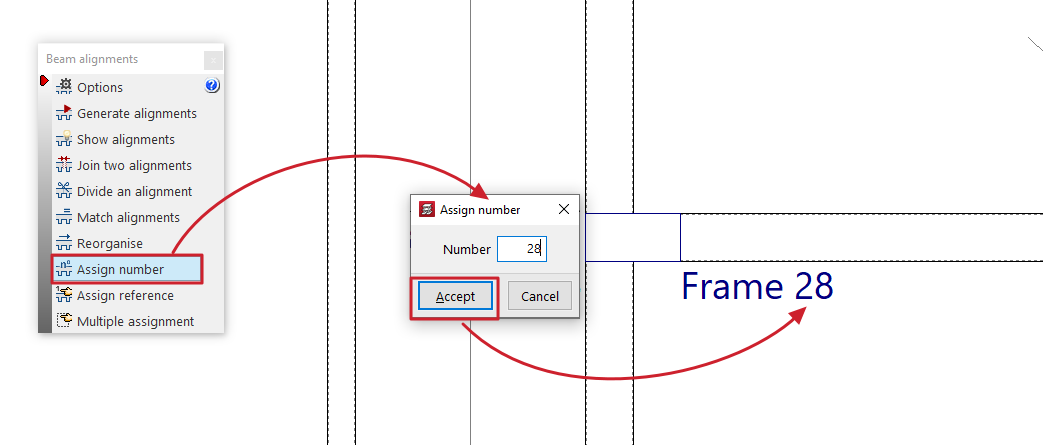
Assign number
The "Assign number" option allows you to assign a different alignment or portal number than the one automatically generated according to the criteria established in the options in this menu.
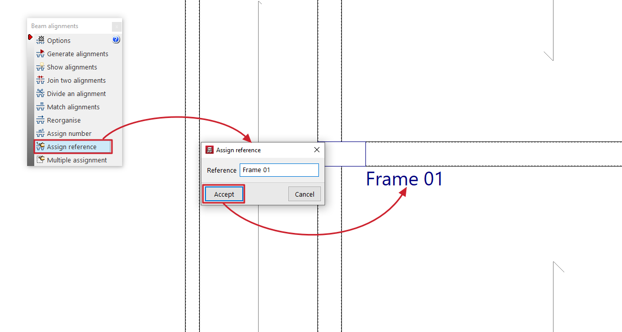
Assign reference
The "Assign reference" option allows you to select an alignment and modify its reference by typing it directly into the dialogue box that appears.
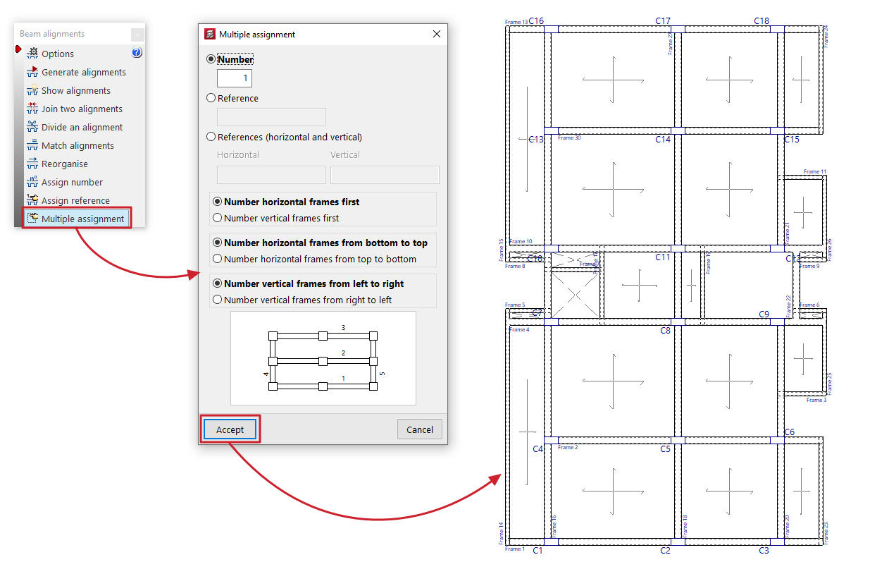
Multiple assignment
The "Multiple assignment" option allows you to simultaneously modify the number or reference of all selected alignments.
You must select one of the following three options:
- Number
If this option is selected, enter the starting number from which the numbering will be generated. - Reference
If this option is selected, the reference of the first frame is entered, from which the rest of the references will be assigned by increasing the last letter or number. - References (horizontal and vertical)
If this option is selected, the references for both the first vertical frame and the first horizontal frame are written, from which the rest of the references will be assigned by increasing the last symbol alphabetically or numerically.
The options at the bottom of the dialogue box allow you to configure the automatic numbering performed by the program:
- Number horizontal frames first / Number vertical frames first (if "Number" or "Reference" is selected)
- Number horizontal frames from bottom to top / Number horizontal frames from top to bottom
- Number vertical frames from left to right / Number vertical frames from right to left
After accepting the dialogue box, select the desired alignments one by one or using a capture area, then right-click to confirm the operation.
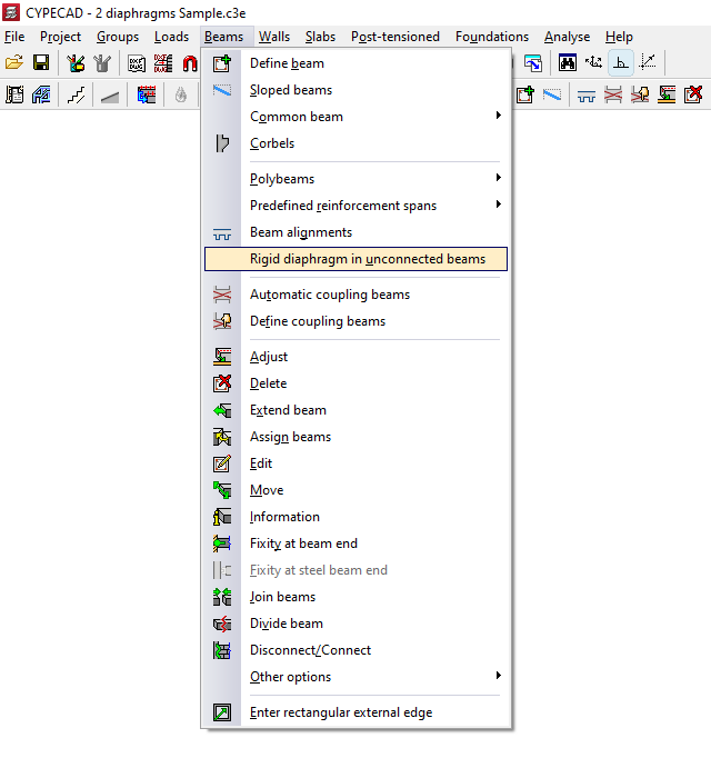
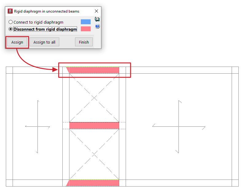
Rigid diaphragm in unconnected beams
With the option "Rigid diaphragm in unconnected beams" in the "Beams" menu of the "Beam input" tab, you can manage the behaviour of cantilever beams as rigid diaphragms, i.e. beams that are not in contact with any floor slab.
Clicking on the option opens a dialogue box with two options:
- Connect to rigid diaphragm
Beams that are considered connected to the rigid diaphragm have 3 degrees of freedom, maintaining the rigid diaphragm loadcase. - Disconnect from rigid diaphragm
Beams disconnected using this option will have six degrees of freedom at each end with the corresponding stresses: axial, moment in the vertical and transverse planes, vertical and transverse shear, and torsional moment; therefore, their reinforcement will be dimensioned for all of them.
The beams assigned to each of these situations are highlighted in a different colour on the floor plan.
The "Assign" button allows you to select the freestanding beams to which the selected condition will be applied, either one by one or by selecting an area, while "Assign to all" applies the selected condition to all freestanding beams on the floor. The "Finish" option closes the dialogue box.
Beams that are not supported by any floor slab are considered, by default, to be connected to the rigid diaphragm.
For the purposes of considering buckling in horizontal, steel or concrete beams, the buckling length is considered to be the free length of the beam in both the vertical and horizontal planes.
| Note: |
|---|
| It is advisable to disconnect the cantilever beams that connect two independent areas of the floor belonging to different diaphragms (e.g., several independent block slabs with cantilever beams from block to block) from the rigid diaphragm. On the other hand, it will not be necessary to disconnect a cantilever beam if it is an isolated beam connecting two regions of the same diaphragm (for example, beams forming the boundary of openings within a slab of the same block). |
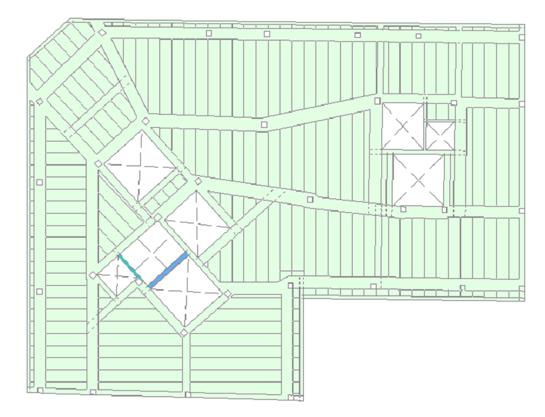
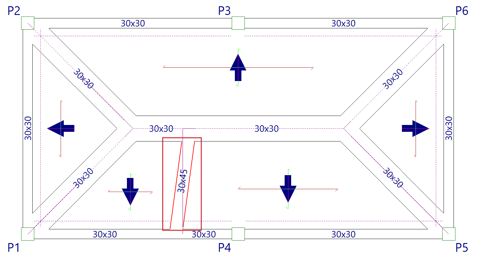
Coupling beams
The following options within the "Beams" menu of the "Beam Input" tab allow you to define the coupling beams of the model.
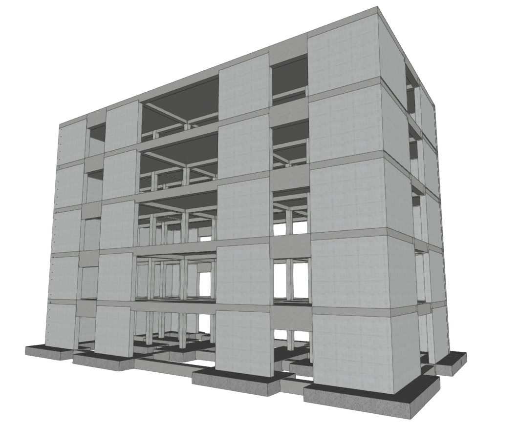
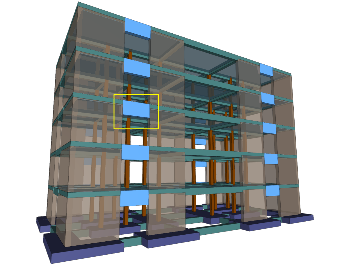
Coupling beams are elements used in the design of seismic-resistant structures, allowing two shear walls aligned on the same plane to be connected. They are elements with very high rigidity that reduce lateral displacement of the structure. The results of the coupling beam analysis obtained in CYPECAD can then be exported to BIMserver.center and imported into programmes such as StruBIM Shear Walls for design and verification.
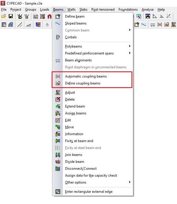
Automatic coupling beams
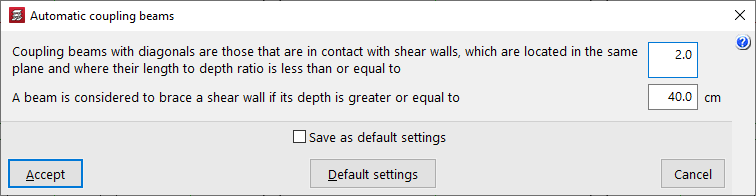
The "Automatic coupling beams" option allows you to define the parameters based on which the programme will automatically assign the coupling beam function to beams when using the corresponding option in "Define coupling beams" in the same menu.
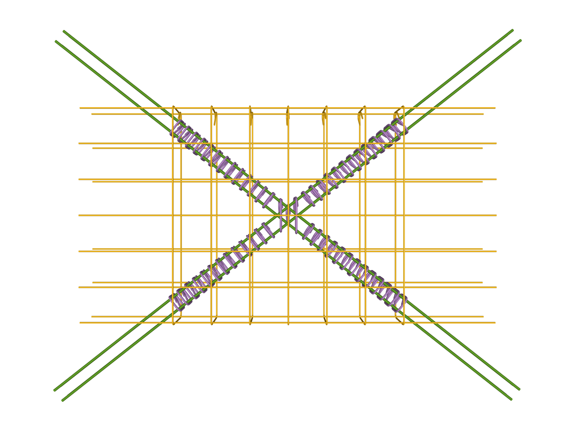
Thus, coupling beams with diagonals will be those that are in contact with shear walls located in the same plane and in which the ratio between their length and their depth is less than or equal to the first value indicated (default 2).
Furthermore, a beam will be considered to brace a shear wall if its depth is greater than or equal to the second value indicated (by default, 40 cm).
Define coupling beams
The "Define coupling beams" option allows you to assign or unassign the coupling beam function to beams previously entered in the model that have the appropriate cross-section.
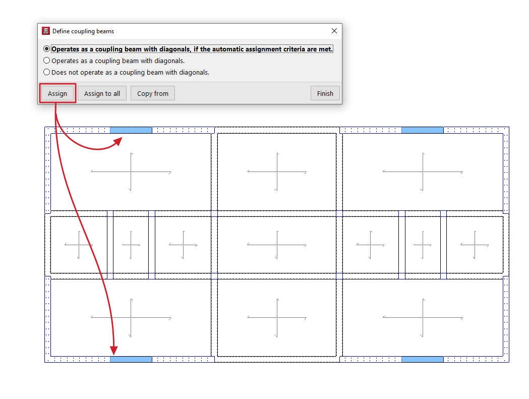
When you click on the option, a dialogue box appears where you can choose one of the following options:
- Operates as a coupling beam with diagonals, if it meets the automatic assignment criteria are met
It allows you to assign the coupling beam function to the beams selected later if they meet the conditions defined using the "Automatic coupling beams" tool. - Operates as a coupling beam with diagonals
It allows you to force the assignment of the coupling beam function to the beams selected later. - Does not operate as a coupling beam with diagonals
The beams selected subsequently will lose the coupling beam function.
At the bottom, the "Assign" option allows you to select the beams in the floor plan to which the selected condition will be assigned, while "Assign to all" will apply the selected condition to all beams in the floor plan where possible. On the other hand, "Copy from" allows you to extract information from a specific beam on the floor plan to define the current beam. The "Finish" option allows you to end the operation without changes.
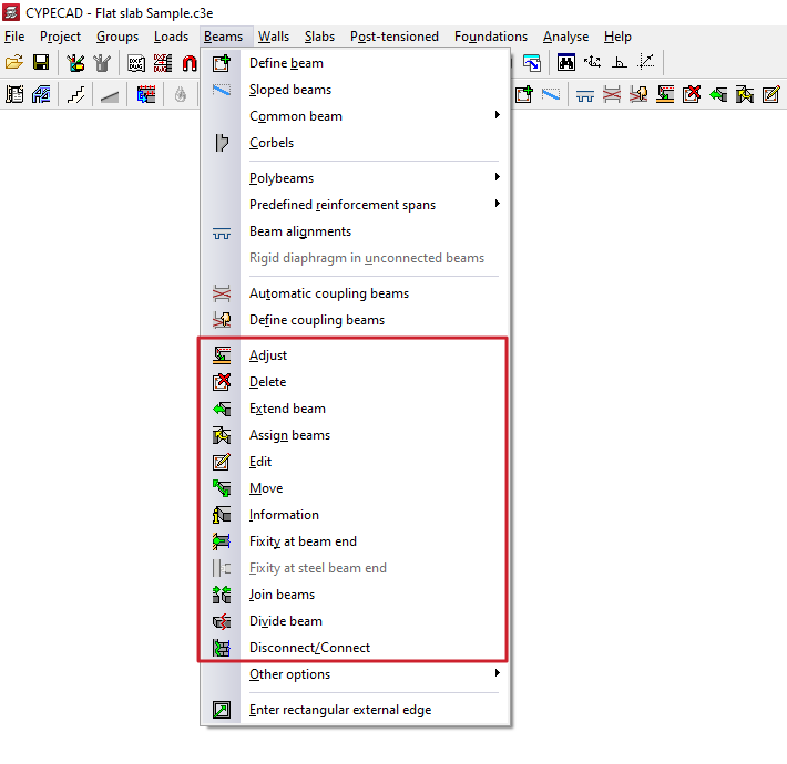
Adjustment and configuration tools in the "Beams" menu
The program offers the following tools for adjusting and configuring beams in the "Beams" menu, within the "Beam input" tab:
- Adjust
- Delete
- Extend beam
- Assign beams
- Edit
- Move
- Information
- Fixity at beam end
- Fixity at steel beam end
- Join beams
- Divide beams
- Disconnect/Connect
Each of these tools is described below:
Adjust
The "Adjust" option allows you to adjust the position of a beam by aligning its faces or axis with the faces or axes of nearby columns or screens, as well as with lines from a DXF/DWG template, contours, maximum slope lines, or intersection lines of inclined planes.
- To adjust one end of the beam, left-click on it, moving the cursor close to the face you wish to adjust and keeping the cursor outside the beam.
- To adjust both ends of the beam at the same time, i.e. to adjust the entire beam, click on the centre of the beam, close to the corresponding face, and keep the cursor outside the beam.
- The adjustment can also be made to axes. To do this, left-click on the end or centre of the beam, keeping the cursor within the beam.
- If you want to adjust to a DXF or DWG template or to a contour, you must first select the "Capture to templates" option in the toolbar and, in the dialogue box that appears, choose the "Nearest" capture. When you do this, the "Fit" option will adjust the beams to the DXF or DWG template lines or contours and not to the faces or axes of columns, until the snaps are deactivated.
- If inclined planes have been defined previously, right-clicking the mouse will bring up a dialogue box with the option "Adjust to intersection of planes / lines of maximum slope". Activating this option allows the following:
- If two sloping floors are found on a beam, it is possible to adjust the beam to the intersection line of the two planes of these floors.
- If a beam is defined on an sloped plane, it is possible to adjust the beam to a line that passes through its centre and takes the direction of maximum slope of the plane or the direction perpendicular to the maximum slope of the plane, depending on which is closest to the current direction of the beam.
Delete
With the "Delete" option, you can remove any beam you have entered. You can remove a beam by clicking on it with the left mouse button or, after clicking the right mouse button, by entering the beam number in the dialogue box that appears.
If a beam is divided by another beam (for example, in the case of a beam supporting a roof truss), only the indicated section of the beam is deleted.
When deleting a beam that divides two panels, use the left mouse button to select the panel you wish to keep. After deleting the beam, this panel will cover the surface of the two previously existing panels.
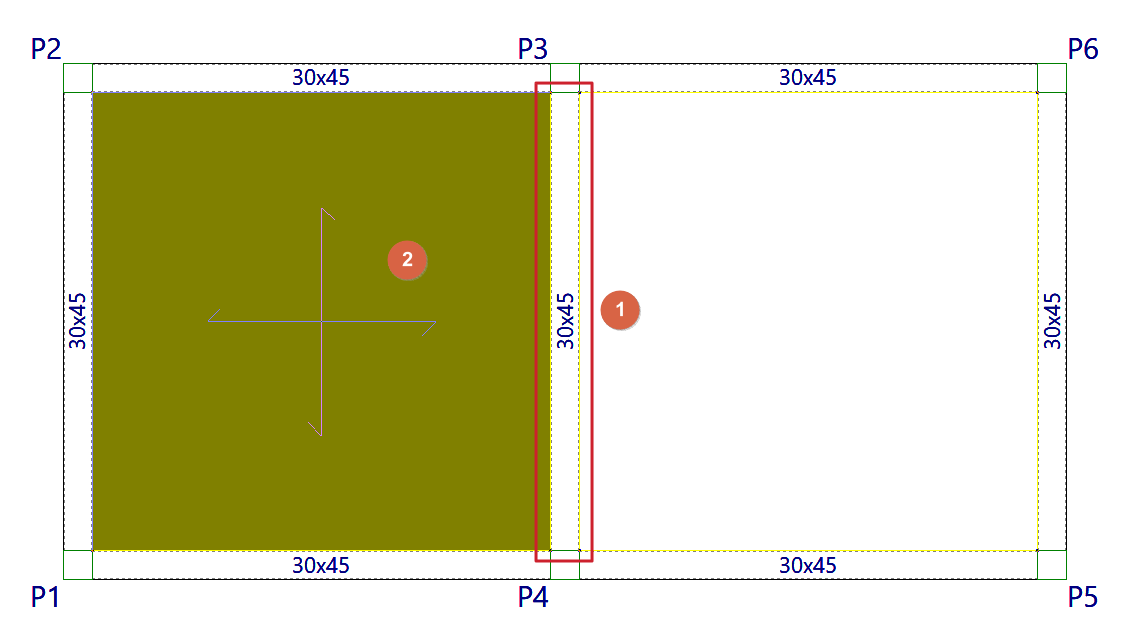
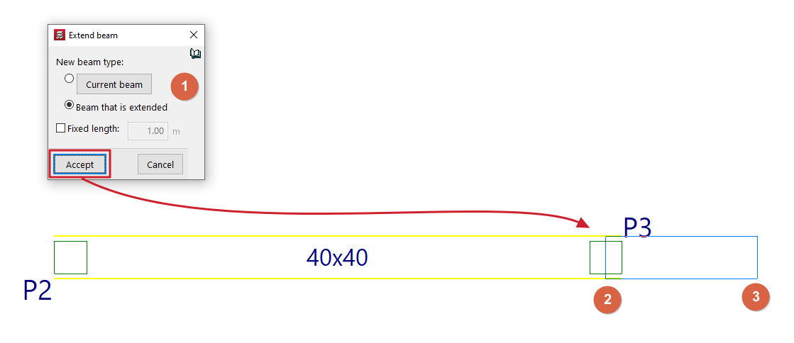
Extend beam
With the "Extend beam" option, you can move the end of a beam in the direction of its axis.
When you click on the option, a dialogue box appears where you must indicate the "Type of new beam" that will be applied to the extended section. This can be the definition applied to the "Current beam", which can be viewed and modified by clicking on the corresponding button, or the same data can be taken from the "Beam being extended".
If the "Fixed length" box is checked, the beam will be extended by the length indicated in the field provided for this purpose. To do this, when you hover the pointer over a beam in the floor plan, a preview of the extension will be displayed, which can be validated by clicking with the left mouse button.
If the "Fixed length" box remains unchecked, select the beam and then use the left mouse button to mark the new position of one of its ends on the floor plan.
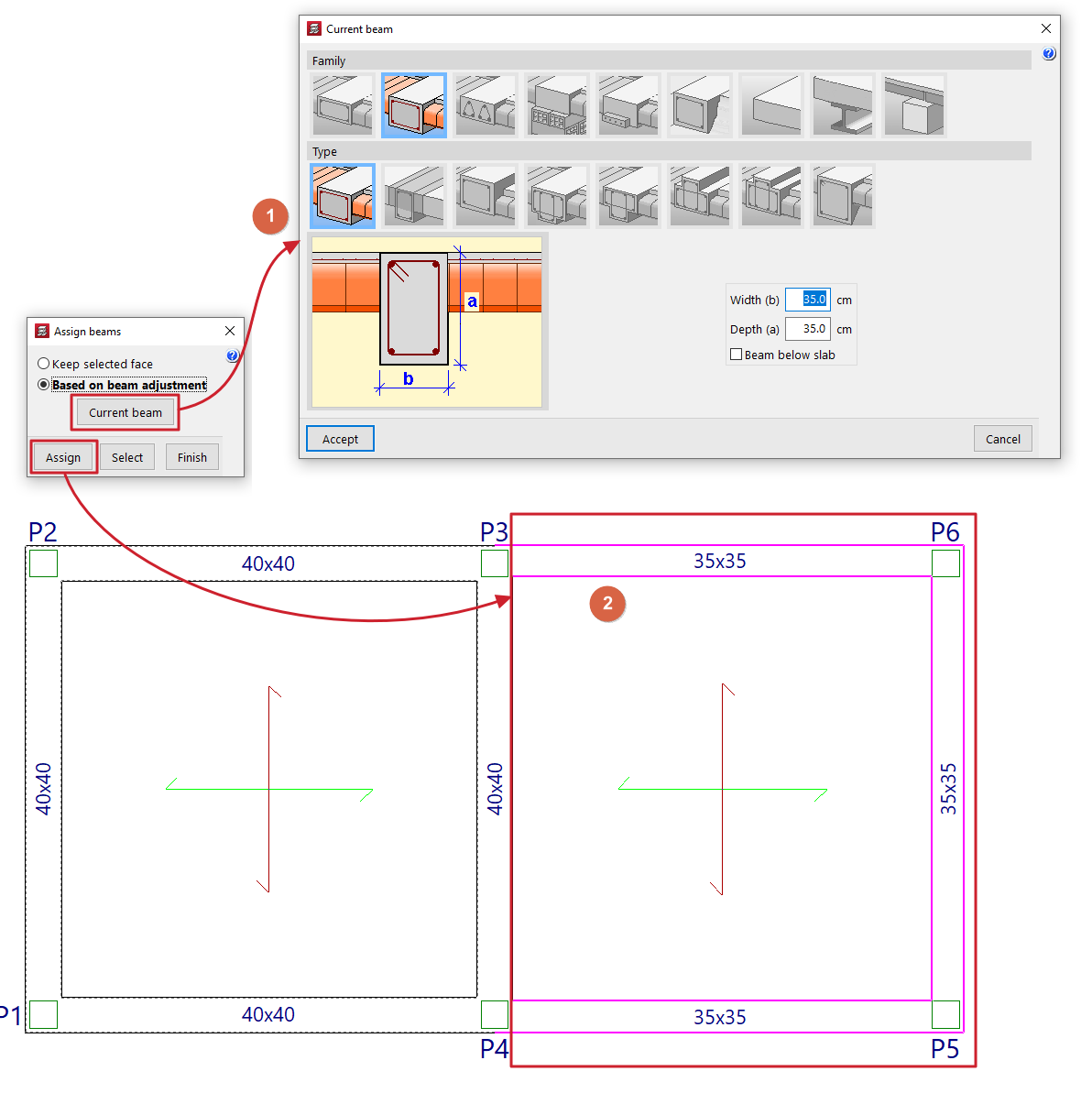
Assign beams
The "Assign beams" option allows you to copy the characteristics of the last beam entered (or current beam) to beam spans already entered in the model by selecting them in plan view. This allows you to change the data of existing beams without having to delete and re-enter them.
Clicking on the option opens a dialogue box with the following options:
- Keep selected face fixed
This option allows you to keep one of the faces or the axis of the beam fixed when assigning new dimensions. To do this, when selecting an individual beam, place the cursor on the outside of the beam and close to the face you want to keep fixed, or on the inside of the beam if you want to keep the beam axis fixed. This option cannot be used if multiple beams are assigned. - According to beam setting
This option allows you to maintain the original setting defined in the beam when assigning new dimensions, regardless of the position of the pointer when selecting the beam. This option can be used both in individual assignment to a beam and in multiple assignment to several beams.
The "Current beam" button allows you to view and modify the data for the current beam or the last beam entered, which will be assigned to the selected beams.
At the bottom, the "Assign" option allows you to select the beams in the plan to which the data will be assigned, while "Select" allows you to extract the information from a specific beam in the plan to define the current beam. The "Finish" option allows you to end the operation without changes.
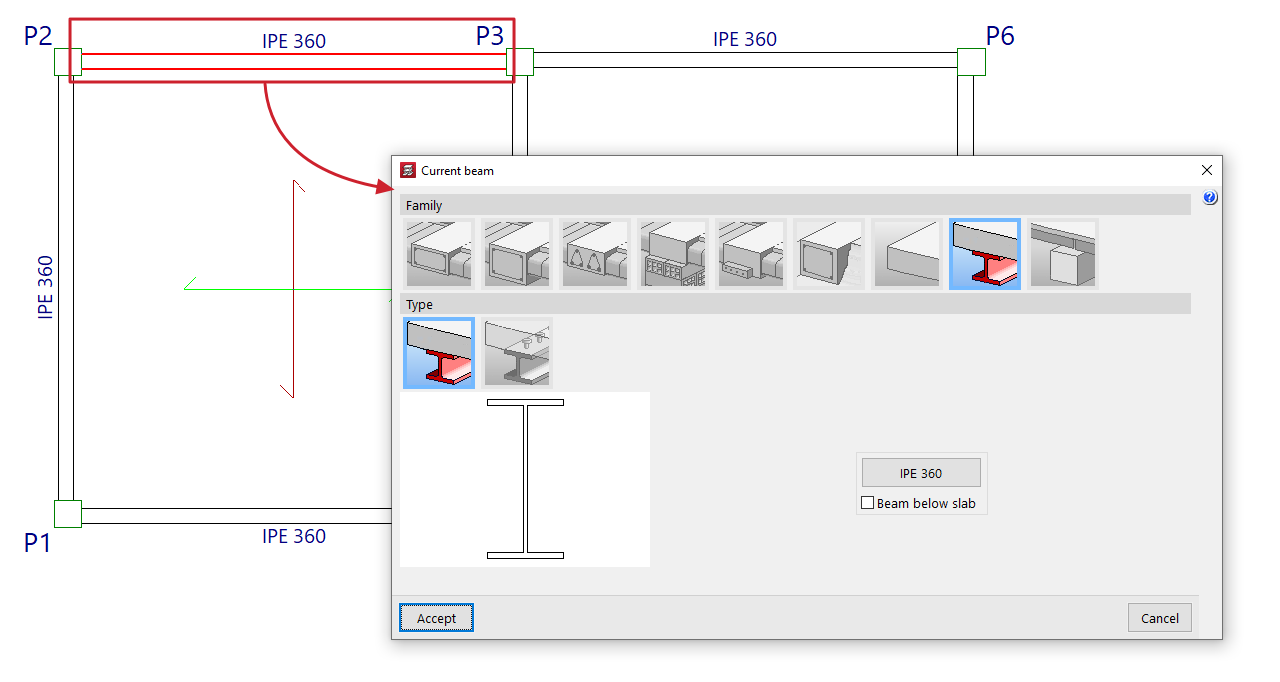
Edit
With the "Edit" option, you can edit and change the characteristics of the beam section selected in the floor plan.
The program will open the beam definition window so that you can enter the desired configuration, which will be applied to the beam when you click on "Accept".
Move
With the "Displace" option, you can move the end of a beam (keeping the other end fixed) or move the entire beam in parallel, based on a defined displacement value.
When you select this option, the message line at the bottom of the program interface will display the value of the "Current offset" or offset that will be applied. You can change this value by right-clicking and entering the new offset value in the dialogue box that opens.
Next, to move the beam, place the cursor near the end or centre of the beam and click on the side towards which you want to move it, depending on whether you want to move only one end or the entire beam in parallel.
Information
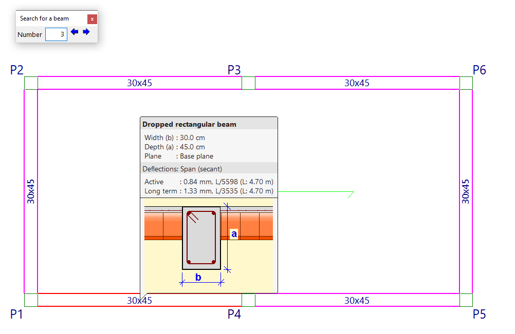
The "Information" option allows you to display an information box on the screen about the characteristics and results of the beam selected in the plan.
To do this, select the beam with the mouse pointer, or type its "Number" in the corresponding field of the "Search for a beam" dialogue box that appears and press 'Enter'. When you do this, the beam will be marked in red and the rest of the beams that are the same as the selected beam will be marked in magenta.
If you click the right mouse button, or if you use the "Next beam" option in the dialogue box that appears, you will see the information for the beam following the current one. Similarly, the "Previous beam" option allows you to view the information for the beam with the number preceding the current one.
If the structure has been calculated, information about the deflections calculated for each beam will also be displayed. If any deflection limit is exceeded, its value will be shown in red.
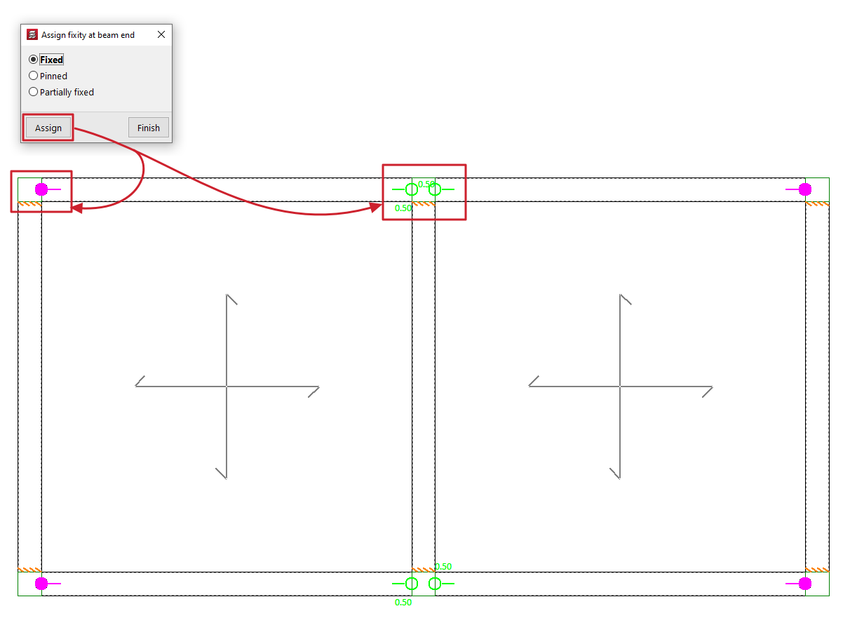
Fixity at beam end
This option allows you to assign the type of fixity at the ends of beams made of any material.
Clicking on it opens the "Assign fixity at beam end" window, where you can select the type of support from those available. This can be:
- Fixed
- Pinned
- Partially fixed
In this case, a value between 0 and 1 must be defined.
After selecting one of the above, click on "Assign" and select the end or ends of one or more beams by marking them one by one or using a capture area.
Each type of recess or joint is represented on the screen by a different symbol.
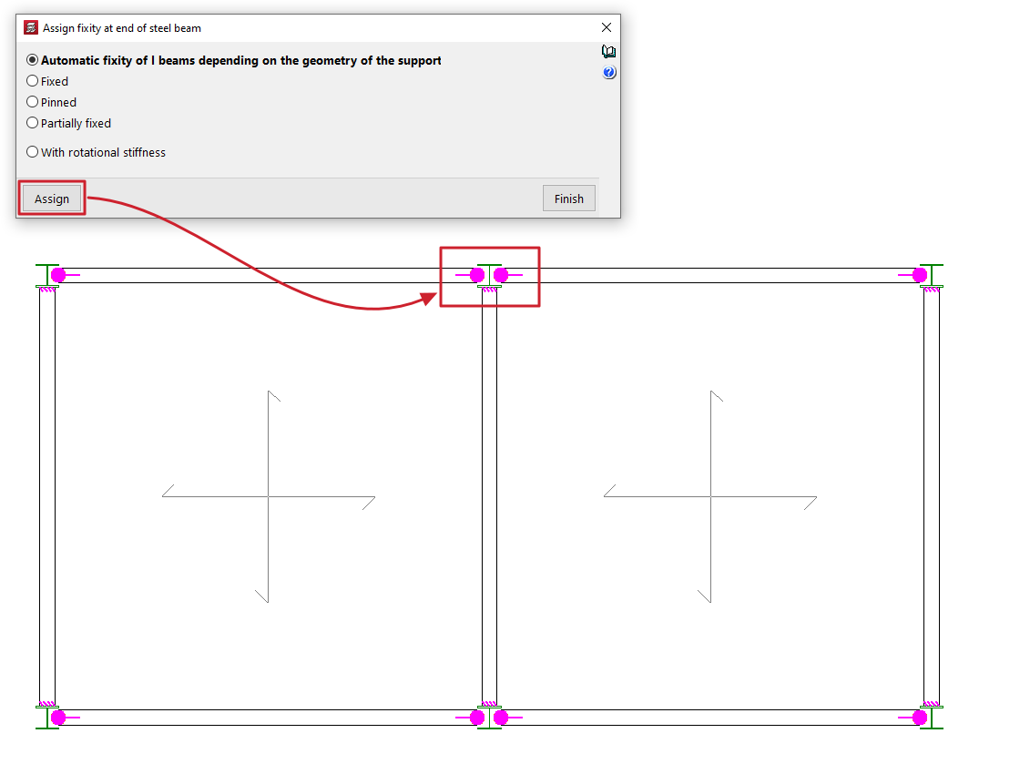
Fixity at the end of a steel beam
This option allows you to assign the type of fixity at the ends of the metal beams.
Clicking on it opens the "Assign fixity at end of a steel beam" window, where you can select the type of embedding from those available. This can be:
- Automatic fixity of I beams depending on the geometry of the support
This option is only available for I beams made of rolled or reinforced steel. When this option is selected, a hinge will be automatically assigned to the end of these beams if that end rests on the web of a column or another beam with a double T section. Otherwise, a fixed support will be assigned. - Fixed
- Pinned
- Partially fixed
In this case, a value between 0 and 1 must be defined. - With rotational stiffness
In this case, the rotational stiffness value must be entered at the end of the part. The program provides help in explaining the effects of "Consideration in the analysis model of rotational stiffness at the ends of parts".
After selecting one of the above, click on "Assign" and select the end or ends of one or more metal beams by marking them one by one or using a capture area.
Each type of recess or connection is represented on the screen by a different symbol.
Join beams
The "Join beams" option allows you to join two aligned beams with matching ends and the same cross-section.
To do this, two sections of beams with these characteristics are marked on the floor plan using the left button.
Divide beams
The "Divide beam" option allows you to split a beam into several sections.
To do this, after clicking on the option, mark the point on the beam where you want to make the division and click the left button.
Division may be necessary, for example, if a section change is desired.
Disconnect/Connect
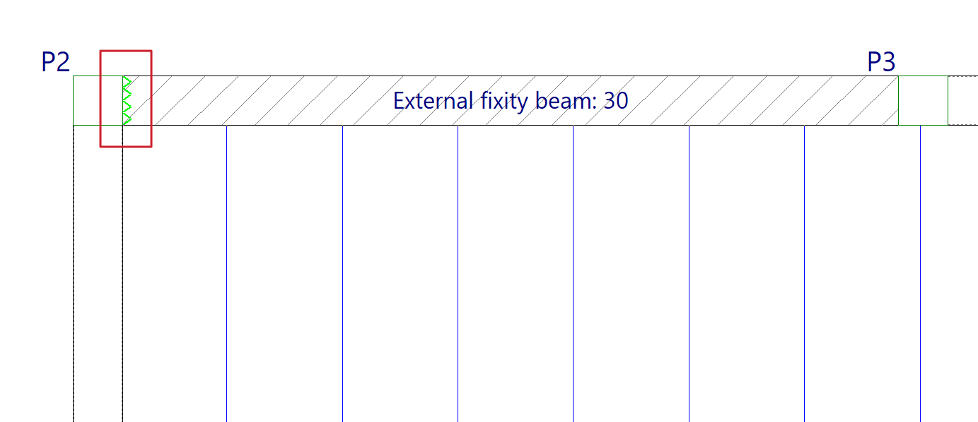
The "Disconnect/Connect" option allows you to disconnect or connect the ends of the "Beams with external connection" (entered from "Beams > Enter beam" and representing supports on piers, supports on walls or embedments) with the columns.
When disconnecting a beam with external connection from a column, the vertical movement of the column will not be impeded by this type of beam. The program will represent this disconnection by drawing a sawtooth symbol on the contact face of the beam with the column.
Otherwise, the beam with external connection will be connected to the column and the column's vertical displacement will be impeded by this beam.
| Note: |
|---|
| This disconnection of this type of beam from the columns is only effective in one-way slabs, since slabs and composite slabs are also connected directly to the columns, not only through the side beams. If this problem is encountered, it is advisable to use other types of designs, for example, by removing the beam with external connection and defining the wall element completely from "Walls > Enter wall". |
Assign data for the capacity check
The "Assign data for the capacity check" option is located in the "Beams" menu of the "Beam input" tab and appears in projects where seismic action has been activated.
This option allows the contribution of the effective width of the slab to be considered in the analysis of the beam's yield moments for capacity checks.

To do this, tick the "Assign slab contribution" box in the pop-up window and enter the following values:
- the "Effective width (1)" for positive moments,
- the "Effective width (2)" for negative moments,
- the "Effective depth (3)",
- the "Mechanical ratio of the bottom reinforcement",
- and the "Mechanical ratio of the top reinforcement".


After clicking on "Assign", select the side wall at the end of the beam in contact with a pillar from which the data will be copied. The meeting points are represented on the plan by triangular symbols. These symbols are filled in with colour if the previous box has been ticked, lighting up in magenta if they have the same data assigned as in the dialogue box.
The "Copy from" option allows you to take the data from the selected meeting point on the floor plan, while the "Finish" option allows you to exit the dialogue box.

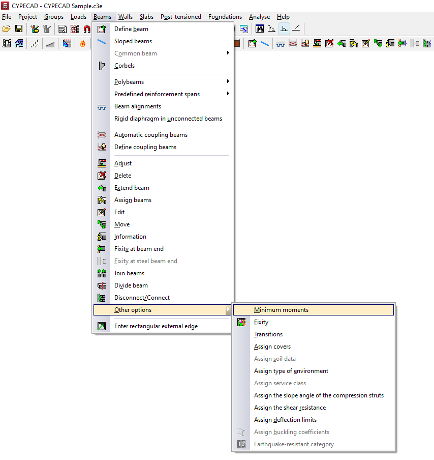
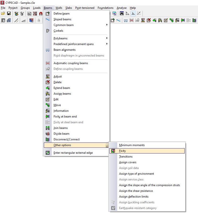
Minimum moments in beams
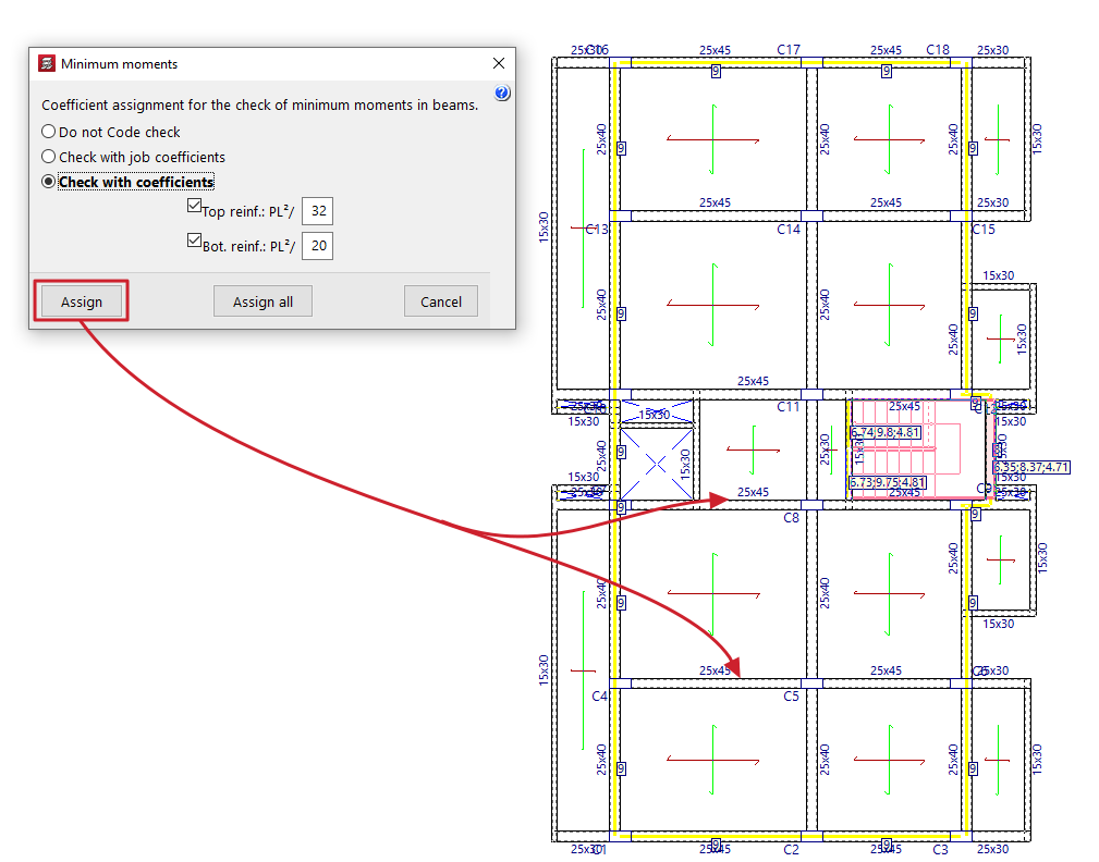
With the "Minimum moments" option in the "Other options" menu, within "Beams", on the "Beam input" tab, you can assign minimum bending moments to be covered to the beams, both negative and positive.
To do this, in the pop-up window that appears, you must select one of the following options related to the "Coefficients assignment for the check of minimum moments in beams":
- Do not Code check
In this case, the minimum moment check will not be performed. - Check with job coefficients
If this option is selected, the minimum moments will be checked using the coefficients defined in "Construction > Beam options > Minimum moments to be covered with reinforcement in beams". - Check with coefficients
If this option is selected, it is possible to enter the value that defines the minimum negative and positive moments. By default, these values are:- Top reinforcement: PL2/32
- Bottom reinforcement: PL2/20
The "Assign" button allows you to select the beams to which the selected condition will be applied one by one, while "Assign all" applies the selected condition to all beams on the floor. The "Finish" option closes the dialogue box.
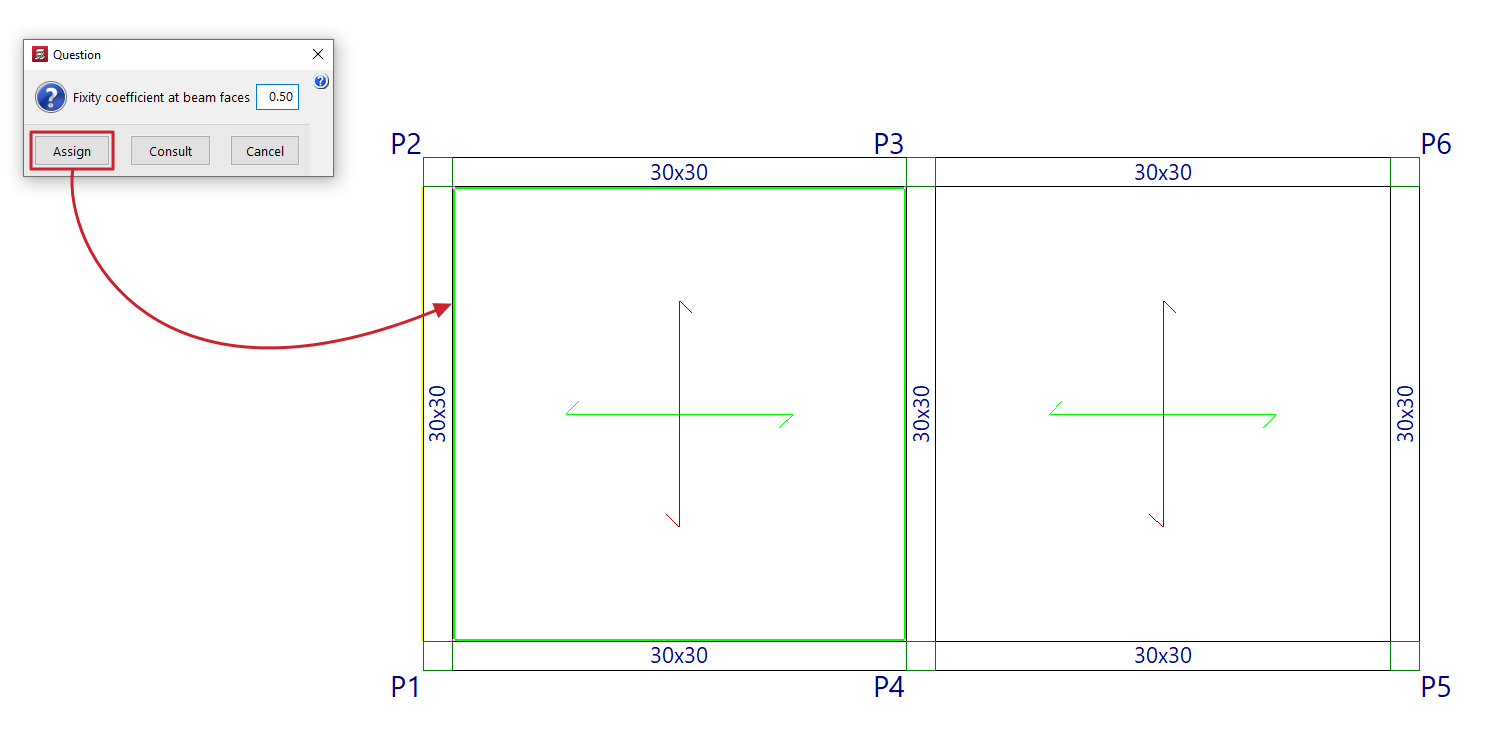
Fixity in beam faces
The "Fixity" option in the "Other options" menu, within "Beams", on the "Beam input" tab, allows you to fully or partially articulate slab ribs and connect them to the faces of the specified beams and to beam axes in the case of joist slabs.
To do this, in the dialogue box that appears, you can enter the desired "Fixity coefficient in beam faces". This value can vary between 0 (hinged) and 1 (fully embedded).
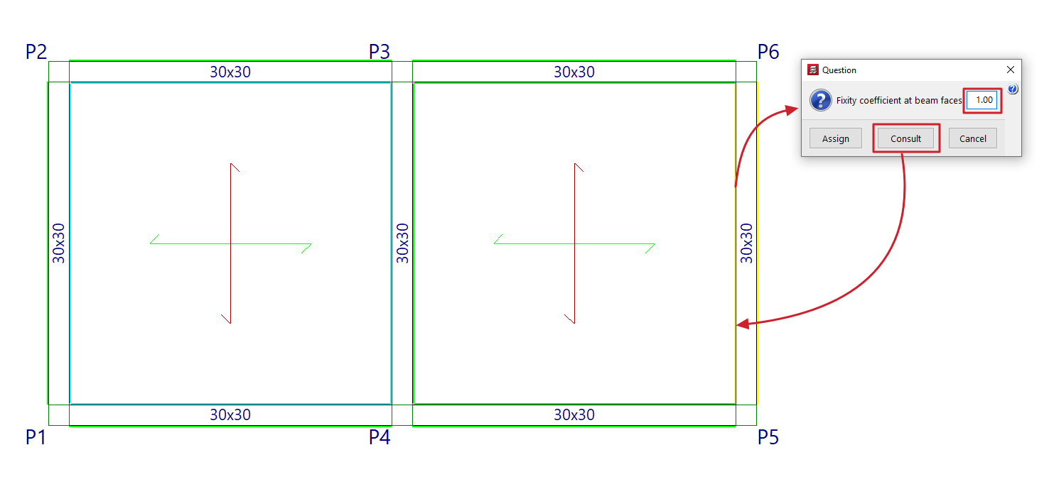
Then, click on "Assign" to apply the value entered in the dialogue box to the faces of the beams selected with the left mouse button, or on "Consult" to examine the value applied to the faces of the beams (clicking with the left mouse button will open the dialogue box with the applied value).
The program will use colour coding to indicate the values entered in the model elements:
- Light green indicates items that have the same data entered in the dialogue box.
- The cyan colour indicates elements that have data entered that differs from that defined in the dialogue box and also differs from the program's default data.
- Elements that have data entered that differs from that defined in the dialogue box are shown in black, and this data is also the same as the program's default data.
Transitions between beams
When selecting the "Transitions" option in the "Other options" menu within "Beams", in the "Beam input" tab, right-clicking opens a window showing the different possibilities for resolving the change in section (due to differences in width) where two beams meet a column.
The terms "Left side" and "Right side" refer to the order in which the beam is inserted: when looking from the starting point to the end point of the beam, the left side will be the side on the left of the beam, and the right side will be the opposite.
Once the transition has been chosen for both sides, accept the dialogue box and left-click on the column in the model to make it effective.
The selection of one transition or another does not influence the analysis of the beams, and should be chosen with the sole criterion of facilitating the bending of reinforcements at the change of section.
Data assignment in beams ("Other options" menu)
The program offers the following tools for assigning data to beams in the "Other options" menu, within "Beams", on the "Beam input" tab:
- Assign covers
- Assign soil data
- Assign type of environment
- Assign service class
- Assign the slope angle of the compression struts
- Assign shear resistance
- Assign deflection limits
- Assign buckling coefficients
Each of these tools is described below:

Assign covers
The "Assign covers" option allows you to assign the covers to the beams defined in the "General project data" (within the "Project > General data" menu) or indicate some "Specific covers for the beam".
In the latter case, the dialogue box shows the "Top cover", the "Bottom cover" and the "Side cover".
| Note: |
|---|
| Since all beams in a frame must have the same covers, if different covers are defined, the program will automatically divide the alignments so that all the beams that comprise them meet this condition. |

Assign soil data
La opción "Asignar datos del terreno" permite escribir y asignar datos tanto a las "Vigas de cimentación" como a las "Losas apoyadas en el terreno".
En el cuadro de diálogo que aparece al pulsar sobre esta opción, es posible activar las casillas correspondientes para "Asignar el módulo de balasto", escribiendo su valor, y/o para "Asignar las tensiones admisibles" del terreno, escribiendo su valor tanto para "Situaciones persistentes" como para "Situaciones sísmicas y accidentales". El botón de la derecha permite "Importar valores usuales de proyecto" seleccionando un tipo de terreno entre los disponibles (como gravas, arenas, limos o arcillas).

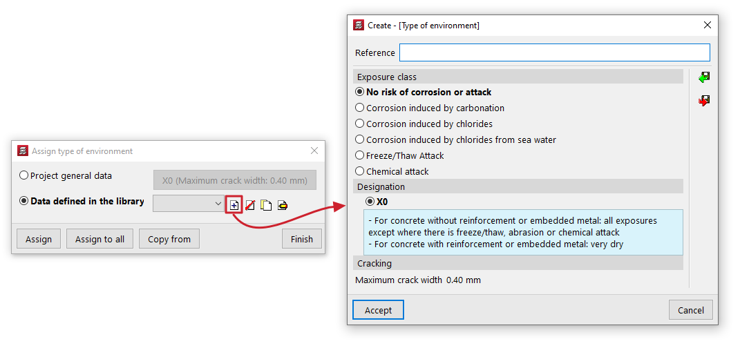
Assign type of environment
The "Assign type of environment " option allows you to assign the environment type to the beams by selecting the one defined in the "General project data" (which can be modified in the same dialogue box or in the "Project > General data") or indicate a different environment type from the "Data defined in library".
In the latter case, the type of environment is created by indicating a "Reference" and selecting the "Exposure class" and its "Designation", which gives a value of "Maximum crack opening".
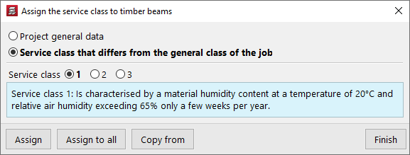
Assign service class
The "Assign service class" option allows you to assign the service class to the timber beams, either by selecting the class defined in the "General project data" (within the "Project > General data") or by indicating a "Service class different from the general one for the project".
In the latter case, you must select the "Service class" from those available in the dialogue box.
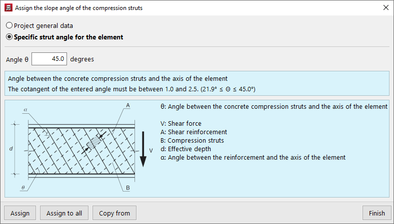
Assign the slope angle of the compression struts
The "Assign the slope angle of the compression struts" option allows you to modify the slope angle of the compression struts with the axis of each part.
You can select the value defined in the "General project data" (in the "Project > General data > By position > Beam options > Dimensioning/Checking" menu) or enter a "Specific strut angle for the element".
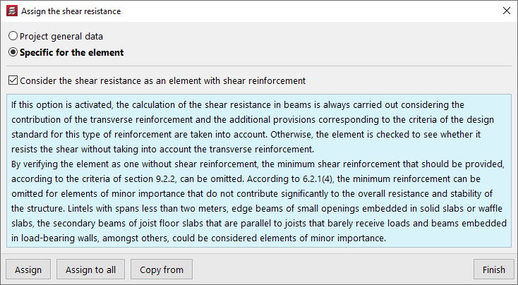
Assign the shear resistance
The "Assign shear resistance" option allows you to adjust the calculation of shear resistance in beams, either by using the settings defined in the "General project data" (in the "Project > General data > By position > Beam options > Design/Check") or by selecting a "Specific to the element" setting.
In this case, it is possible to activate or deactivate the checkbox "Consider shear resistance as a shear-reinforced element":
- If this option is activated, the shear resistance of beams is always calculated considering the contribution of transverse reinforcement, and the additional provisions corresponding to the criteria of the standard for this type of reinforcement are taken into account.
- Otherwise, it is first verified whether the element can withstand the required shear force without taking the transverse reinforcement into account.
Assign deflection limits
The "Assign deflection limits" option allows you to assign deflection limits to beams, either using those defined in the "General project data" (in the "Project > Beam options") or by selecting the limits from the "Data defined in library".
In this case, the dialogue box allows you to create and set deflection limits for beams made of different materials: "Concrete", "Rolled steel", "Formed steel" and "Timber".
By pressing the edit button on the right, you can configure the following arrow limits for each material:
- Instantaneous, by simple hypothesis type (Permanent load, Overload)
- Snapshot, by type of action combination (Characteristic, Frequent, Quasi-permanent)
- Infinite term, by type of combination of actions (Characteristic / Frequent, Quasi-permanent) (for "Concrete" and "Timber")
- Long-term active, by type of combination of actions (Characteristic, Frequent, Quasi-permanent)
In some cases, the wizard in the top right-hand corner allows you to import the deflection limit values from the "Design conditions" of the standards selected in the "General data".
The other options on the sidebar allow you to import and export the information on the configured deflection limits to .bibgen files saved on disk.

Assign buckling coefficients
The "Assign buckling coefficients" option allows you to define and assign the following parameters related to the buckling check of elements in compression and the lateral buckling check, both for steel beams and timber beams:
- Check buckling of elements in compression
In this section, by activating the boxes "XY buckling" and/or "XZ buckling" it is possible to define the "Buckling length" or the "Buckling coefficient" of the element, as well as the "Moment coefficient" in both planes. - Check lateral buckling
In this section, by activating the boxes "Positive bending (Top flange)" and/or "Negative bending (Bottom flange)" boxes, it is possible to define the "Lateral buckling length" or the "Lateral buckling coefficient" of the element, as well as the "Moment coefficient" in both wings. The "Critical moment modification factor" is also defined.

At the bottom of the dialogue box for each of these options, the "Assign" option allows you to select the beams in the floor plan to which the selected condition will be assigned, while "Assign to all" will apply the selected condition to all beams in the floor plan where possible. On the other hand, "Copy from" allows you to extract information from a specific beam on the floor plan to define the current beam. The "Finish" option allows you to end the operation without changes.
Earthquake-resistant category of beams
For the seismic analysis of the structure, the program allows concrete structural beams to be designated as primary beams or secondary beams for the purposes of their performance in the earthquake-resistant system.
To do this, use the "Earthquake-resistant category" option in the "Beam input" tab in the "Beams > Other options" menu.
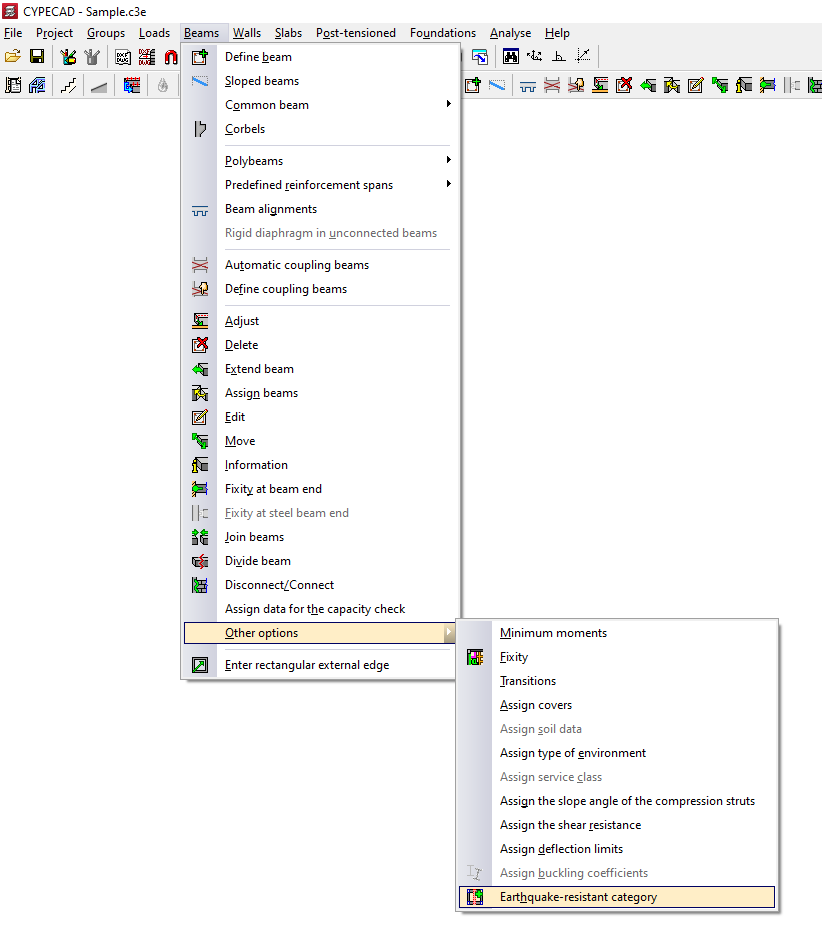
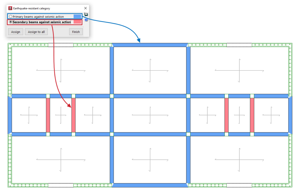
In the dialogue box that appears, select one of the following options:
- Primary beams against seismic action
- Secondary beams against seismic action
The "Assign" button allows you to select the beams to which the selected condition will be applied one by one, while "Assign to all" applies the selected condition to all concrete beams on the floor. The "Finish" option closes the dialogue box.
The program uses a colour code to indicate the condition assigned to the different concrete beams on the floor plan.
Secondary elements in relation to seismic action are structural elements that are not considered part of the building's resistant system for withstanding such seismic actions. Therefore, these elements do not need to meet any special requirements.
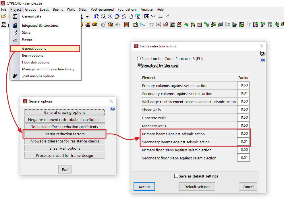
The stiffness of secondary beams for seismic scenarios is reduced according to the value defined in the "Inertia reduction factors" dialogue box (under the "Project > General options" menu). The mass of secondary beams will be taken into account.
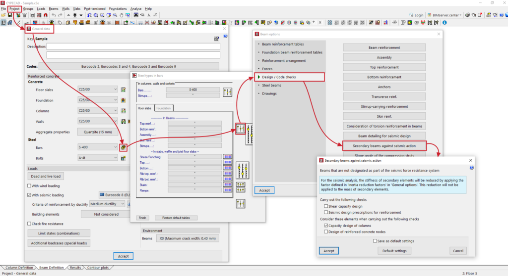
With regard to capacity checks, the designer can indicate how they wish to consider secondary beams according to their judgement in the dialogue "Secondary beams under seismic action" (within the menu "Structure > General data > By position (steel bar calculation options) > Beam options > Design/Check").
Inserting rectangular external edges
The option "Enter rectangular external edge", within the "Beams" menu of the "Beam input" tab, allows you to automatically generate a rectangular perimeter of beams that form the outer edge of a floor slab.
Clicking on this option brings up a dialogue box with the following options:
- Insert rectangular opening with angle 0
- Insert rectangular opening with any angle
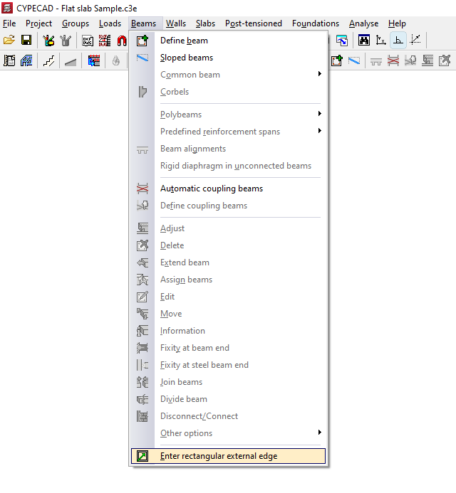
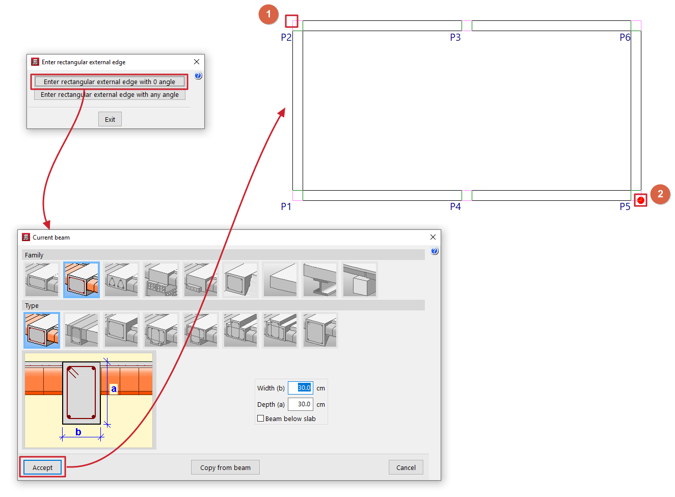
Insert rectangular opening with angle 0
When you click on this option, the "Current beam" window opens first, where you can define the type of beam to be used in generating the edge.
Next, two points must be marked on the floor plan (1 and 2), which will form one of the diagonals of the edge. The beams will follow the directions of the main coordinate axes.
Insert rectangular opening with any angle
When you click on this option, the "Current beam" window opens first, where you can define the type of beam to be used in generating the edge.
Next, mark two points that define one side of the edge (1 and 2) and, finally, a point to define the opposite side (3).
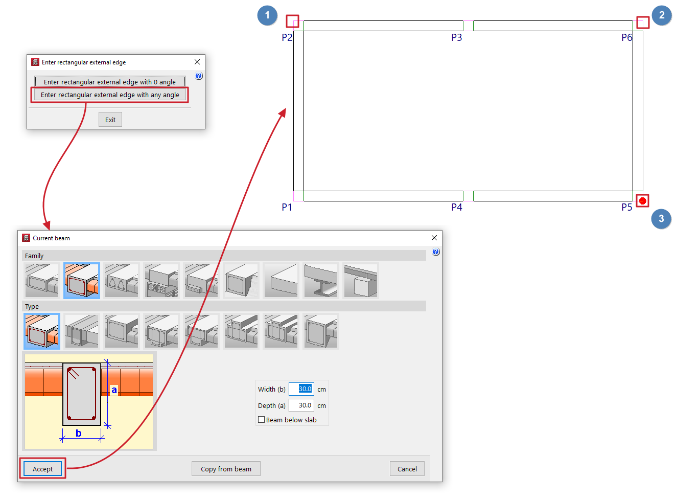
Table of contents
Complete your tour of CYPECAD by exploring the other available sections:
- Introduction
- Introduction and creating new jobs
- General data configuration
- Defining floors and groups of floors and inserting columns, shear walls and starts ("Column input" tab)
- Inserting beams, walls, floor slabs, foundation elements and special elements, and structural analysis (the "Beam Input" tab):
- Checking analysis results and editing elements (the "Results" tab):
- Options on the "Contour plots" tab
- Printing documents and exporting data
- More information:
- General features of CYPECAD