CYPECAD carries out the analysis and design of structures for building and civil works which are subject to vertical and horizontal forces as well as fire exposure.
This webpage explains how geometry and other structure data can be entered.
To enter a structure in CYPECAD, several of the following modes described on this webpage can be combined as desired. The choice of procedure will depend on the user’s preference, the way they receive project or element data, or the information to be entered.
This versatility provides greater speed, reliability and efficiency for the structure entry process.
More general information about this program can be found on the CYPECAD website.
Manual entry by global or relative coordinates
This data entry procedure can be combined with all entry modes at any time.
Columns, beams, walls, etc. can be entered by indicating the following:
- Global coordinates
Once the element to be entered has been chosen (column, beam, wall, etc.), users can type in the X and Y coordinates to place it on the floor shown onscreen. - Relative coordinates
Once the element to be entered has been chosen (column, beam, wall, etc.), users can left-click the mouse at an approximate location of the current floor where they want it to be placed. Next, the program will ask users to type the distance in X and the distance to another nearby element or reference in Y.
Manual entry with the help of DXF or DWG files used as templates
This data entry procedure can be combined with all entry modes at any time.
Columns, beams, walls, etc. can be entered with the help of a drawing in DXF or DWG format. The program allows different types of element snaps from the used DXF or DWG file to be activated so that the positions can be adjusted with maximum millimetre accuracy.
Automatic entry by importing StruBIM CYPE 3D structures
This data entry procedure can be combined with all entry modes at any time.
CYPECAD can import a structure from StruBIM CYPE 3D with the same design assumptions as StruBIM CYPE 3D.
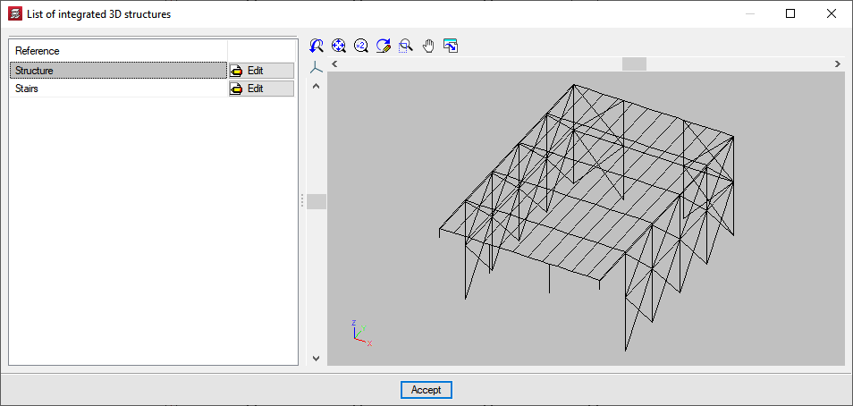
In CYPECAD, an integrated 3D structure is a structure consisting of nodes and bars with six degrees of freedom that is connected and linked to the main building structure managed by CYPECAD.
CYPECAD allows an integrated 3D structure to be entered by creating it directly in CYPECAD, or by importing a project from CYPE 3D on an empty CYPECAD job or with previously entered structural elements.
Several 3D structures can be added to the same CYPECAD project.

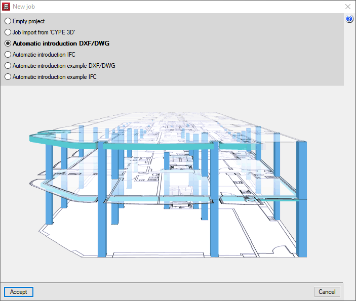
Automatic entry by interpreting information from DXF or DWG files
It is a starting process, i.e. users opt for it when creating a new job.
It can be combined with all other processes, except with the import of files in IFC format and the connection to the BIM model as they are also starting processes.
With the “Automatic entry DXF/DWG” option in the “Automatic job entry: DXF, DWG and CAD/BIM models” CYPECAD module, users indicate certain premises and fill in a series of data, by means of an assistant, that allow the program to read files in DXF and DWG format to automatically generate the structure of the project.
- Interior partition of each floor
- General loads
- Columns
- Outline beams and beams defining internal openings
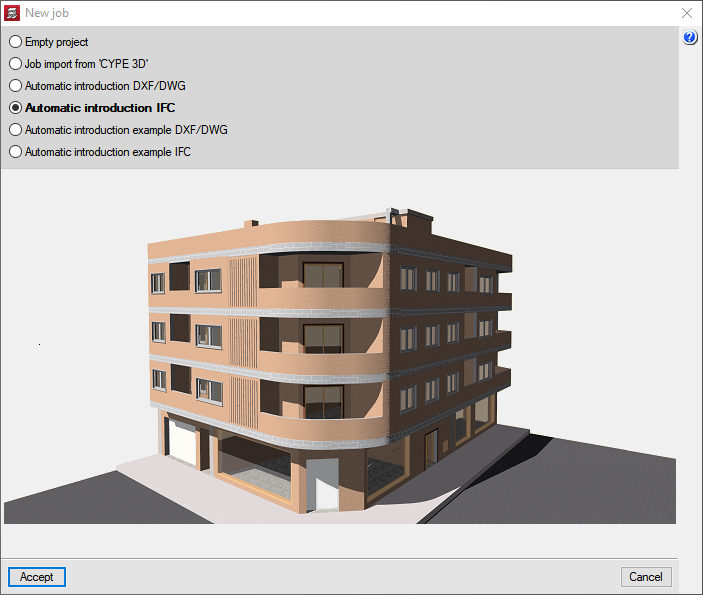
Automatic entry by importing IFC files generated by CAD/BIM programs
It is a starting process, i.e. users opt for it when creating a new job.
It can be combined with all other processes, except with the interpretation of DXF or DWG files and the connection to the BIM model as they are also starting processes.
With the “Automatic entry DXF/DWG” option in the “Automatic job entry: DXF, DWG and CAD/BIM models” CYPECAD module, the information from the selected IFC file is accessed. Next, users confirm and complete the information obtained in the IFC file by means of an assistant, after which the elements of the selected structure are generated automatically. The information that can be extracted from an IFC file (if contained in the file) can include:
- Interior partition of each floor
- Floor loads
- Columns
- Outline beams and beams defining internal openings
- Foundation
- Line loads on partitions and external walls
- Drawing templates of each floor
Entry by connecting to an Open BIM model
It is a starting process, i.e. users opt for it when creating a new job.
It can be combined with all other processes, except with the import of files in IFC format and the connection to the BIM model as they are also starting processes.
CYPECAD is included in the Open BIM workflow. This integration allows CYPECAD to be linked to an Open BIM project hosted on the BIMserver.centre platform so that information can be exchanged via IFC files between the different applications connected to the project.
CYPECAD can import the IFC files of the linked project selected by the user. The information that CYPECAD can obtain from the BIM model is:
- From the IFC file containing the architectural model
This IFC file has been created by CAD/BIM programs that export their model in IFC format (IFC Builder, Allplan®, Archicad®, Revit® Architecture, etc.). From this file, CYPECAD obtains:- The automatic generation of floors
- The automatic generation of columns
- Floor slab outlines, to use them as templates that facilitate their entry
- From the IFC file that contains "security in case of fire" information
The CYPEFIRE CTE application (designed for checking the design and equipment of a building for compliance with Spanish CTE DB SI code for security in case of fire,) exports the fire resistance required in each space via an IFC file that becomes part of the BIM model.
This information allows CYPECAD to automatically assign the fire resistance of the structure’s elements (subject to CYPECAD users’ acceptance). - From any other of the model’s IFC files
CYPECAD generates a 3D view with the remaining applications that provide the Open BIM model with graphic information.
All this information is linked to the Open BIM workflow. CYPECAD, like the rest of the connected applications, will receive notifications of modifications that may have been made to the project and gives users the chance to update them to make the changes they deem appropriate in the structural model.
CYPECAD will export the structural model in IFC format to the Open BIM project so that it can be read by the other applications.