
Views of composite slabs
The "Views" option, within the "Composite slabs" menu on the "Results" tab, allows you to configure how the data obtained from the analysis of composite slab floors is displayed.
These include the specifications and drawings of the plates used, as well as the layouts of the top and/or bottom reinforcements.
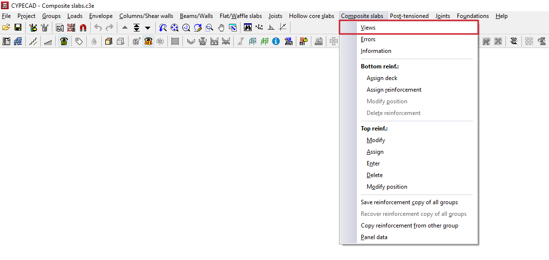
Clicking on this option opens a pop-up window containing the following tools:
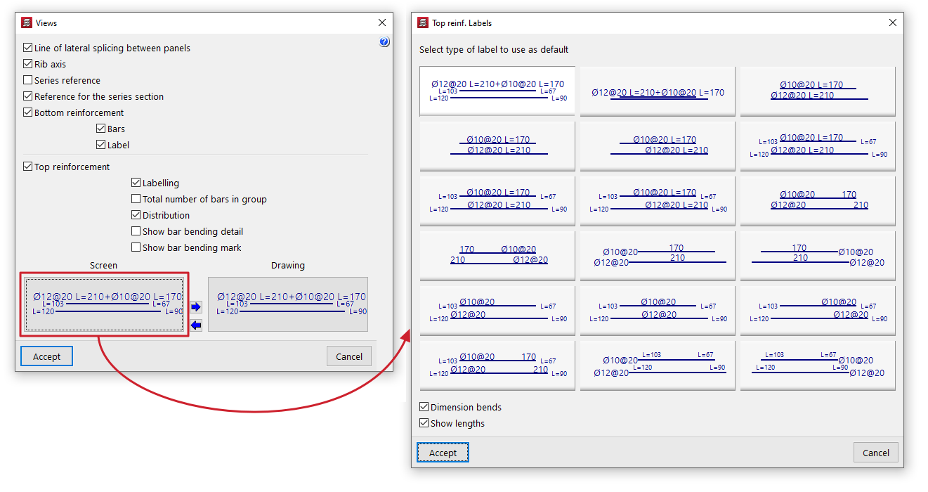
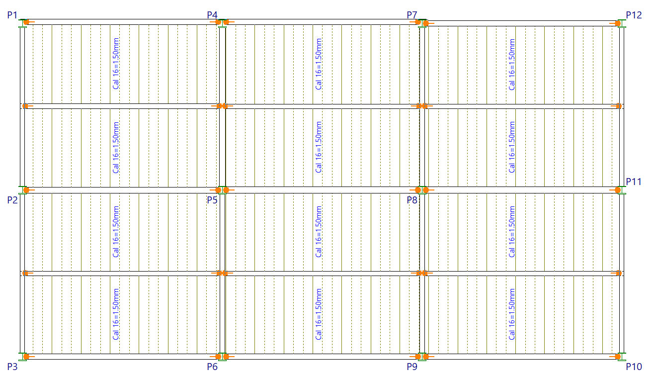
- Line of lateral splicing between panels
Selecting this option draws a solid line to indicate the position of the overlap between each pair of steel panels. - Rib axis
Selecting this option displays the position of the rib axis on the steel plates as a dashed line. - Series reference
Selecting this option labels the series reference of the sheet metal used in each panel of the composite slab on the floor plan. - Reference for the series section
Selecting this option adds a label to the floor plan indicating the section reference of the sheet metal used in each panel of the composite slab. - Reinforcement layout
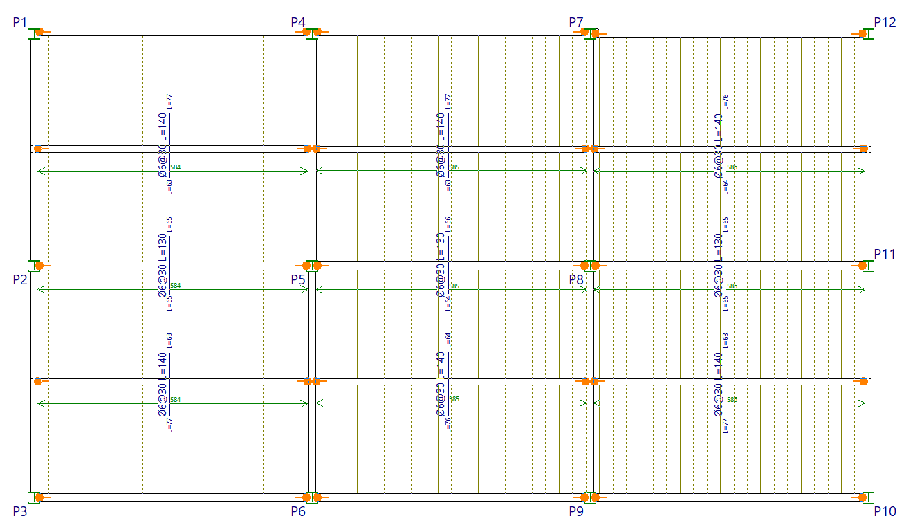
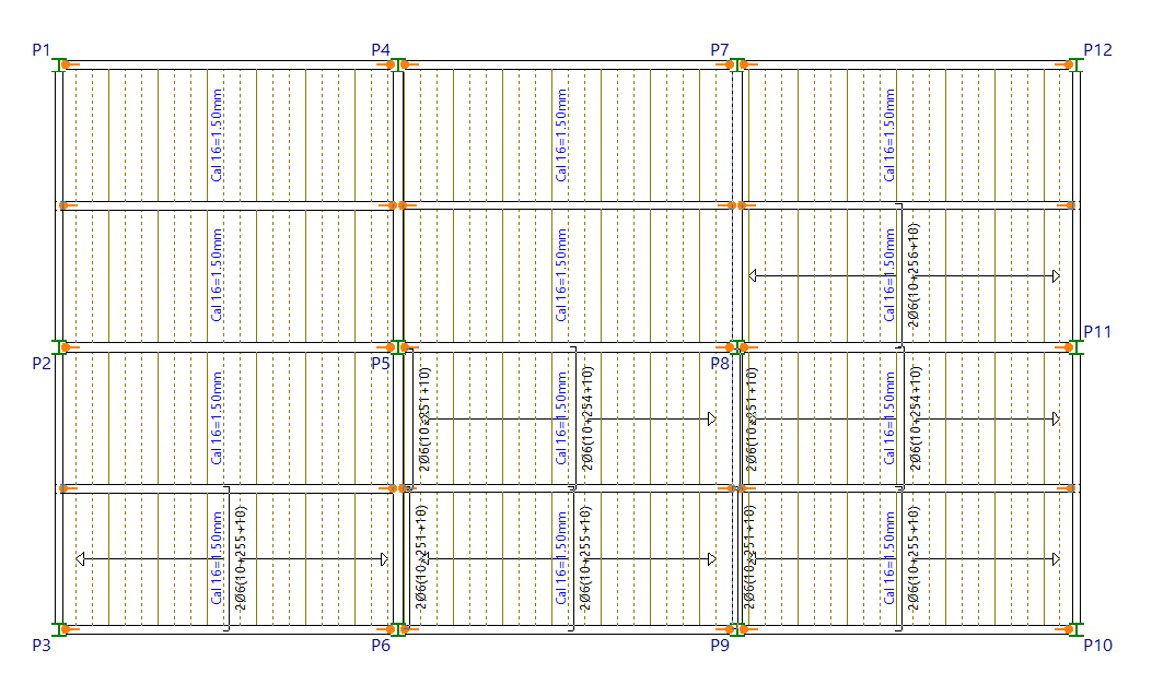
Selecting this option displays the reinforcement layout on the floor plan. You can include the drawing of the "Rebars", as well as the "Labelling" of their diameter and length. - Top reinforcement
Selecting this option displays the layout of the top reinforcement for composite slab floors. You can also configure the following:- Labelling
When this option is enabled, labels indicating the diameters and lengths of the top reinforcement are displayed. - Total number of bars in group
Include the total number of bars in each group of top reinforcement on the label. - Distribution
Add the length measurement to the green line representing the width over which the top reinforcement is distributed. - Show bar bending details
If this option is enabled, a bending diagram is drawn next to the bar in inclined sections. - Show bar bending mark
If this option is enabled, on inclined sections, the bending point is marked with a small line perpendicular to the axis of the bar. - Labelling in "Screen" and in "Plan"
In both cases, the program allows you to select the "Default labelling type" for top reinforcement from those available in the pop-up window. It also allows you to specify whether you wish to "Dimension tabs" and/or "Show lengths" of bars by ticking the relevant boxes. - Copy label selection
These options allow you to copy the label selection on the screen to the label selection in the drawings, or vice versa.
- Labelling
Errors in composite slabs
The "Errors" option, within the "Composite slabs" menu on the "Results" tab, allows you to view the errors obtained following the analysis for each of the composite slab sections.
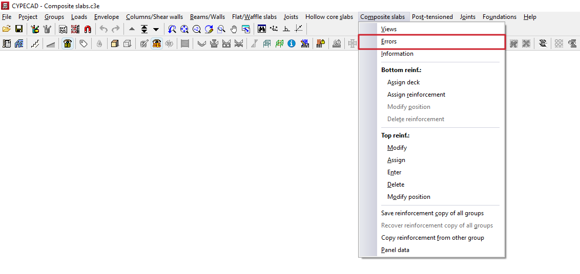
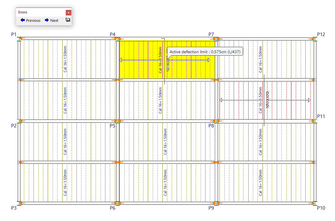
After clicking on this option, any composite slab floor panels with errors in strength or deflection, or any other issues, will be highlighted in red.
For more information about the specific error, left-click on the icon.
The "Previous" and "Next" buttons in the dialogue box allow you to navigate between the other sections of the floor plan that contain errors.
Description and solutions for errors in composite slabs
Below are some of the defects that may occur in the slab surfaces of composite slabs, along with recommended measures to rectify them:
| Error | Description | Solution |
| In the selected series no deck has been found with sufficient thickness: Fails shear check. | No deck thickness has been found in the series that meets this condition in the service phase. | Increase the total depth of the floor slab or change the type of deck. |
| In the selected series, no deck has been found with sufficient thickness: Fails shear check. | No deck thickness has been found in the series that meets this condition in the service phase. | Increase the total depth of the floor slab or change the type of deck. |
| In the selected series, no deck has been found with sufficient thickness: Flexure failure. | No deck thickness has been found in the series that meets this condition in the service phase. | Increase the total depth of the floor slab or change the type of deck. |
| The thickness of the selected deck is not sufficient: Fails shear check. | The deck provided by the user does not meet this condition in the service phase. | Increase the total depth of the floor slab, change the deck thickness or let the program design the necessary deck. |
| The thickness of the selected deck is not sufficient: Fails shear check. | The deck provided by the user does not meet this condition in the service phase. | Increase the total depth of the floor slab, change the deck thickness or let the program design the necessary deck. |
| The thickness of the selected deck is not sufficient: Flexure failure. | The deck provided by the user does not meet this condition in the service phase. | Increase the total depth of the floor slab, change the deck thickness or let the program design the necessary deck. |
| In the selected series, no deck has been found with sufficient thickness to avoid shoring. | This warning appears when the user has opted for the program to design the deck for the execution phase, but there is no deck thickness in the series that meets this condition. In this case, the program places the deck chosen by the user and calculates the spacing between shores. | Reduce the span of the floor structure or install beams perpendicular to the sheets (cross-beams) between the main beams. The spans recommended by some manufacturers may vary between 2 and 3 metres, depending on the floor loads, to ensure a installation that is unshored. |
| Fails shear check. | Appears when additional shear reinforcement is required. However, the program does not allow shear reinforcement in this type of slab. | Increase the floor slab depth. |
| The shear cannot be resisted by this floor slab | The program calculates the shear reinforcement internally, although it is not provided in practice, and this error appears when it cannot find reinforcement to withstand such a force. | Increase the floor slab depth. |
| No reinforcement has been found to meet the existing ultimate moment | The positive bending moment is too large. | Increase the floor slab depth. |
| Compression reinforcement is needed to resist the positive flexure | The flexure makes the concrete unable to resist the existing compression. | Increase the floor slab depth. |
| The width of the rib does not allow for the reinforcement due to compatibility problems with the bar spacing and cover | The bottom reinforcement does not fit in the rib width. | Modify the reinforcement table and reduce the number of bars per rib or increase the floor slab depth. |
| No reinforcement has been found that meets the geometric and mechanical minimums | There is no bottom reinforcement in the table that allows meeting the minimum cited reinforcement ratios. | Edit the reinforcement table as required. |
| Top reinforcement outside table range | The top reinforcement defined in the tables is not sufficient, but the program calculates the necessary reinforcement anyway. | Increase the floor slab depth. |
| Insufficient section for negative moment | The compressed zone does not resist the compressions produced by the negative moment. | Increase the floor slab depth. |
| Required top reinforcement area | The forces exceed the maximum the slab is able to resist. The required area of steel is shown. | Increase the floor slab depth. |
| The width of the floor support beams is not sufficient to anchor the bottom reinforcement correctly. | The lateral cover is greater than the width of the support beam. | Increase the section of the support beam so that it has a greater width |
| Dead load instant. deflection limit | This deflection limit is exceeded. | Increase the floor slab depth. |
| Live load instant. deflection limit | This deflection limit is exceeded. | Increase the floor slab depth. |
| Total instant. deflection limit | This deflection limit is exceeded. | Increase the floor slab depth. |
| Total long-term deflection limit | This deflection limit is exceeded. | Increase the floor slab depth. |
| Active deflection limit | This deflection limit is exceeded. | Increase the floor slab depth. |
Composite slab information
The "Information" option, within the "Composite slabs" menu on the "Results" tab, allows you to view information on the composite slab panels on screen following the analysis, including data relating to their deflection.
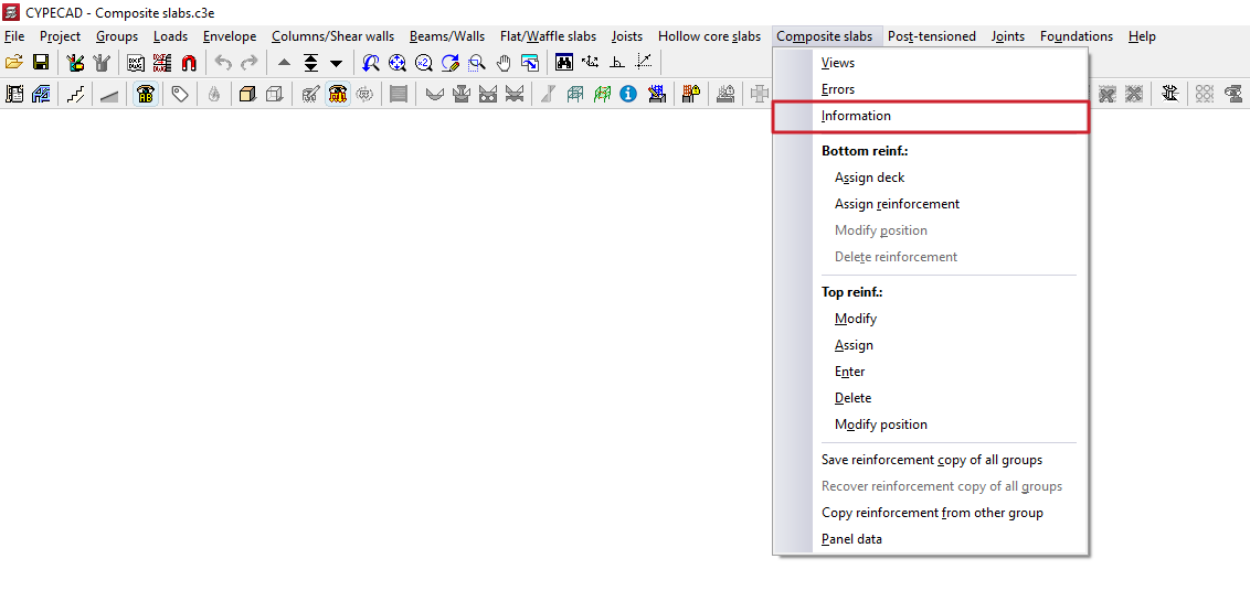
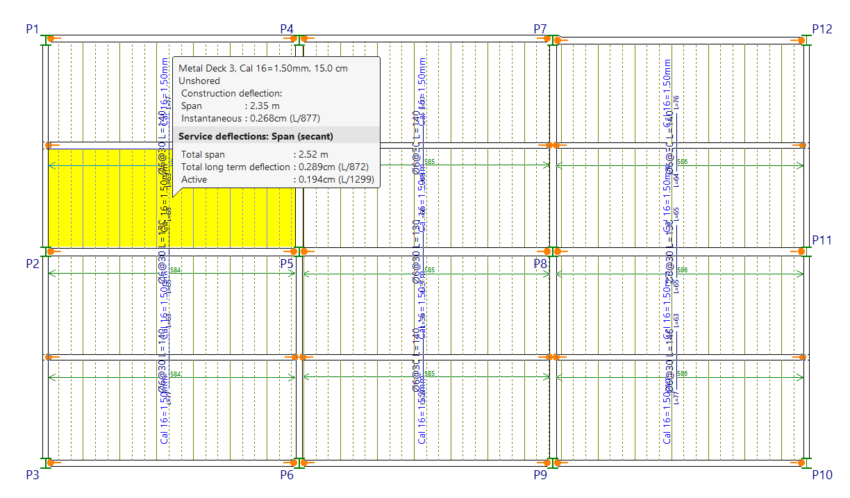
After selecting this option, clicking on each mixed slab panel displays the following information in a box:
- the reference number for the series of plates and the section for the series;
- the edge of the floor slab;
- the supplements required during the implementation phase;
- the current deflection, including data on the load and the instantaneous deflection;
- and the arrows in service, including information on the type of arrow (whether in a "Span (secant)" or "Cantilever (tangent)”), as well as the “Total span”, the “Total deflection at infinity” and the “Active deflection”. Both absolute and relative values are given.
If the deflection could not be calculated, the message "Deflection not available" will be displayed.
Assigning and editing steel plates and positive reinforcement in composite slab floors
The tools in the "Bottom reinforcement" section of the "Composite slabs" menu, within the "Results" tab, allow you to modify the bottom reinforcement generated and laid out by the program following the structural analysis.
Changes made to the bottom reinforcements using the tools in this section are not retained in subsequent analyses; therefore, their use should be reserved for the final adjustment stage prior to printing or exporting the data.
Each of the available tools is described below.
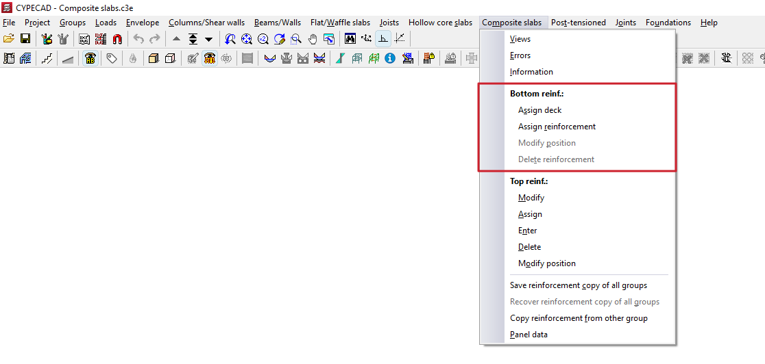
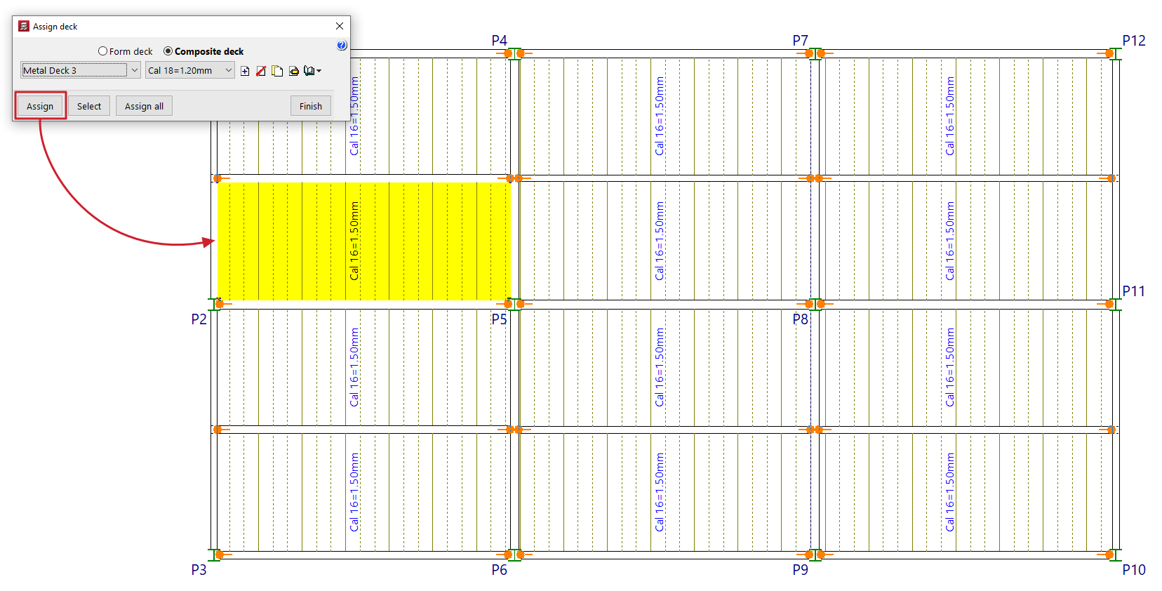
Assign deck
The "Assign" option allows you to change the type of composite slab ("Form deck" or "Composite deck"), the deck series and the type of deck available, by applying these settings to all selected composite slab panels.
To do this, define the data to be assigned in the pop-up window. Then click on "Assign" and select the composite slab floor panels in the floor plan to which you wish to assign this data. In the pop-up window, you can also use the "Select" option to copy the data from a selected slab panel on the floor plan, "Assign to all" to apply it to all the mixed-slab floor panels on the floor plan, or "Cancel" to close the window.
The deck can be modified either before or after the analysis.
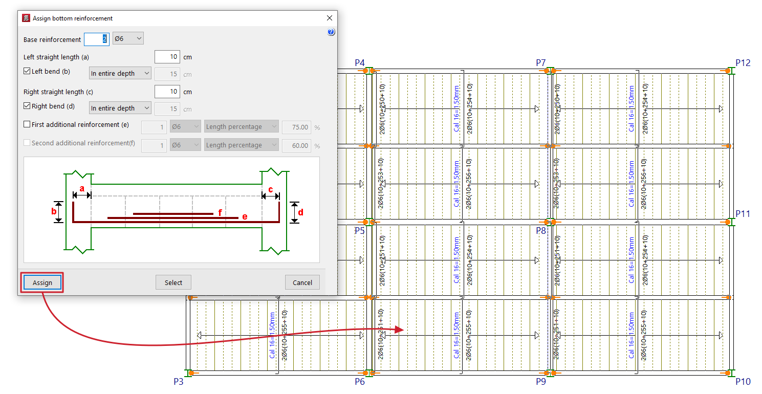
Assign reinforcement
The "Assign reinforcement" option allows you to modify the reinforcement layout in composite slab floors.
To do this, specify the data to be assigned in the pop-up window:
- the "Base reinforcement", specifying the number and diameter of the bars, and including the following details:
- its "Left extension length (a)", with an optional "Left tab (b)" (across the "entire width" or to a "specified length");
- and its "Right straight length (a)", with an optional "Right bend (b)" (across the "In entire depth" or to a "Given length");
- Optionally, a "First reinforcement (e)" and/or a "Second reinforcement (f)" for positive reinforcement may be provided (over the "Full length", a "Specified length" or a "Percentage of length").
The diagram provides a visual aid to help understand each of the defined parameters (a, b, c, d, e, f).
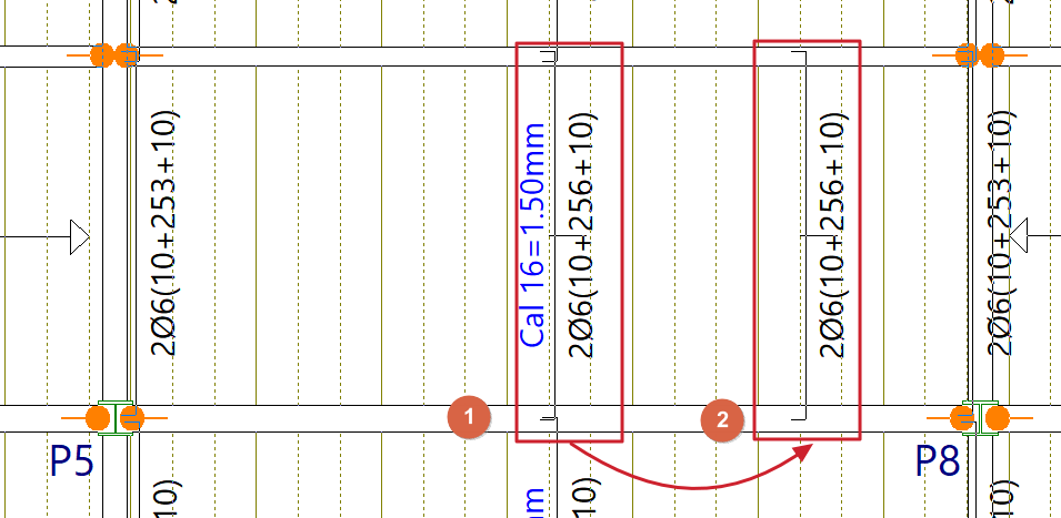
Next, click on "Assign" and select a bottom reinforcement distribution strip on the floor plan to which you wish to assign this data. In the pop-up window, you can also use the "Select" option to copy the data from a selected bottom reinforcement distribution strip on the floor plan, or "Cancel" to close the window.
Modify position
The "Modify position" option allows you to move the display of the top reinforcement from the slab width to another point within the same slab width. This can be useful when the reinforcement label interferes with other text.
To change the position of the reinforcement display, click on the label text in the reinforcement slab width, then click on a point in the same panel to define its new position.
Delete reinforcement
The "Delete reinforcement" option allows you to remove reinforcement bar distribution zones from positive sections.
To do this, select the slab width you wish to delete by tapping it on the screen.
Editing and assigning reinforcement for top reinforcement in composite slab floors
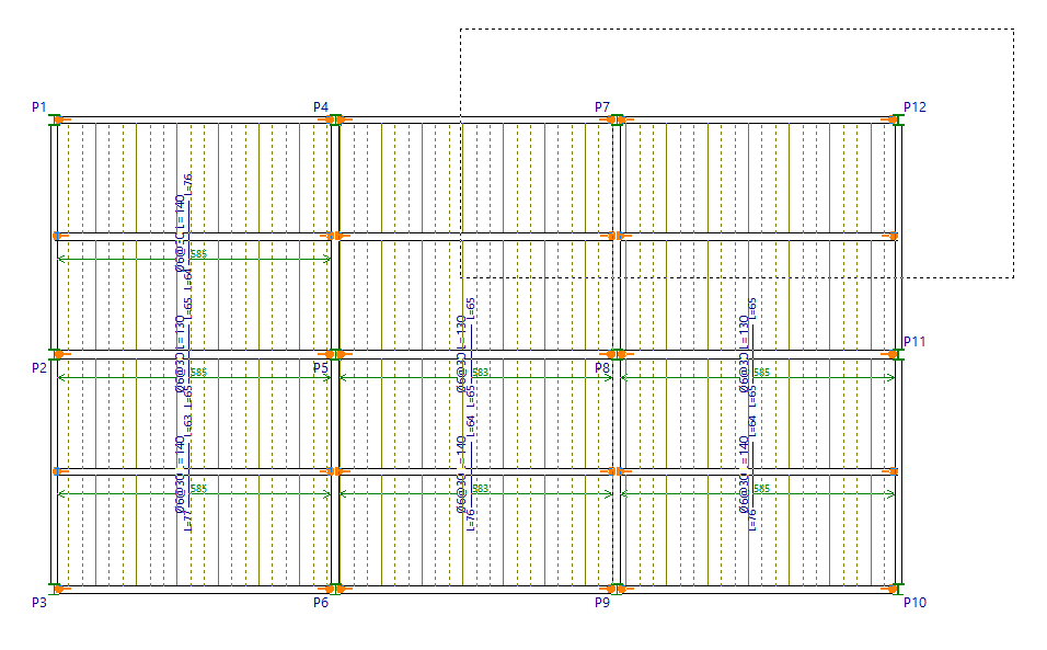
The tools in the "Top reinforcement" section of the "Composite slabs" menu, within the "Results" tab, allow you to modify the top reinforcement obtained in composite slab floors following the structural analysis.
Changes made using the tools in this section are not retained in subsequent redesigns; therefore, they should only be used during the final adjustment stage prior to printing or exporting the data.
Each of the available tools is described below.
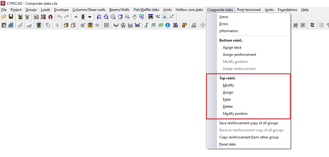
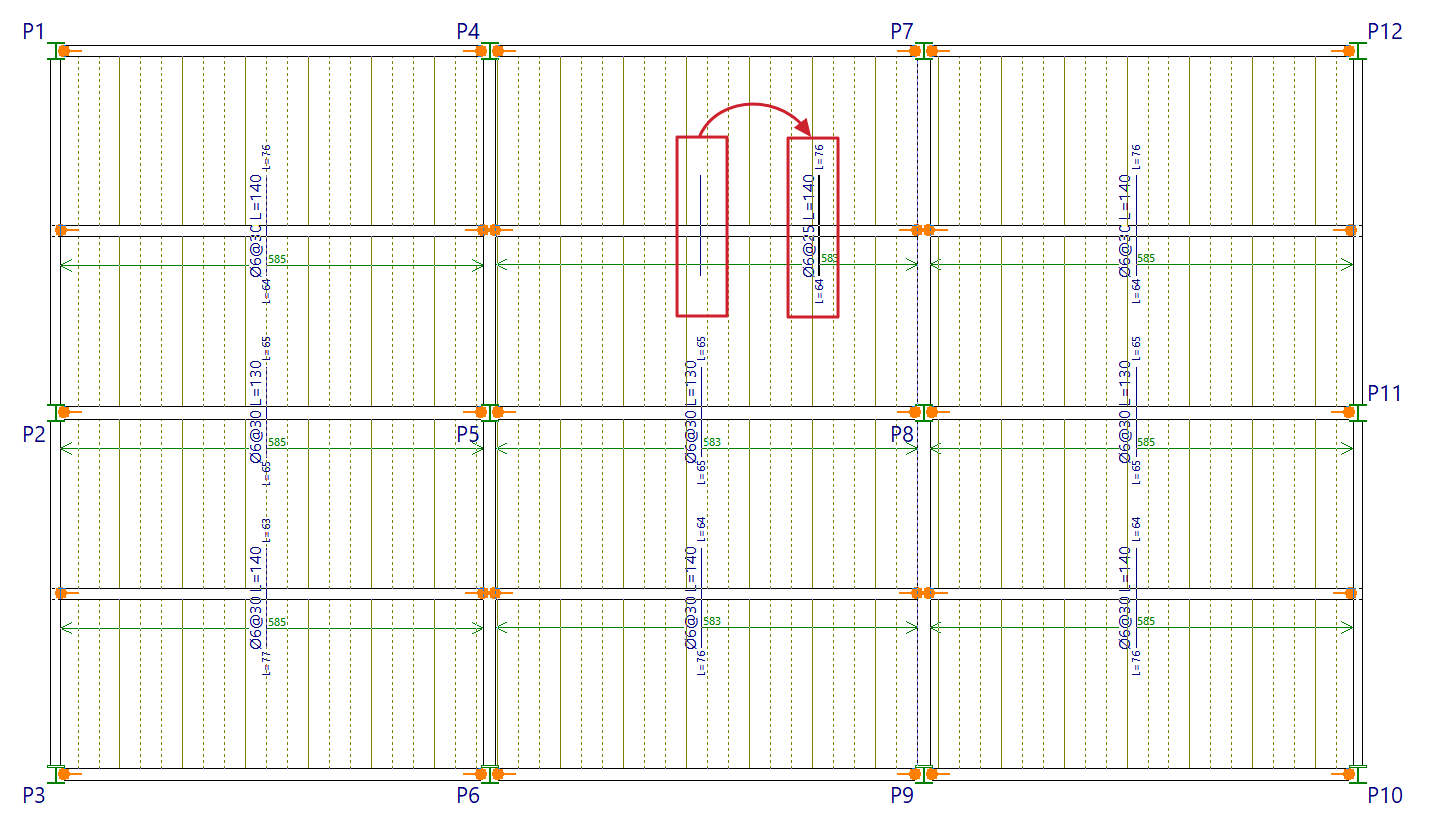
Modify
The "Modify" option allows you to change the number, diameter and length of the reinforcement bars in the top reinforcement. It also allows you to add or remove layers or reinforcement groups.
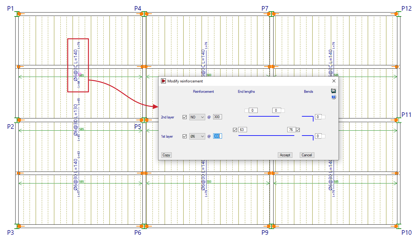
To do this, select the reinforcement to be modified by drawing a box on the plan view.
In the "Modify reinforcement" window that appears, you can modify the "Reinforcement" in the "1st layer" and "2nd layer" by specifying their number, diameter and spacing. You can also enter the "End lengths" (or the lengths of the reinforcement bars on either side of the beam axis), or the length of the "Extensions" (which the program adds in cases where the negative sections meet a slab edge).
The lengths of bars anchored in a straight extension are measured from the nearest beam centreline, whilst the lengths of bars anchored at the end indicate the length from the bend point.
The "Copy" option allows you to extract data from a selected negative assembly on the floor plan, whilst "Accept" applies the data entered in the window to the reinforcements selected when using the option.
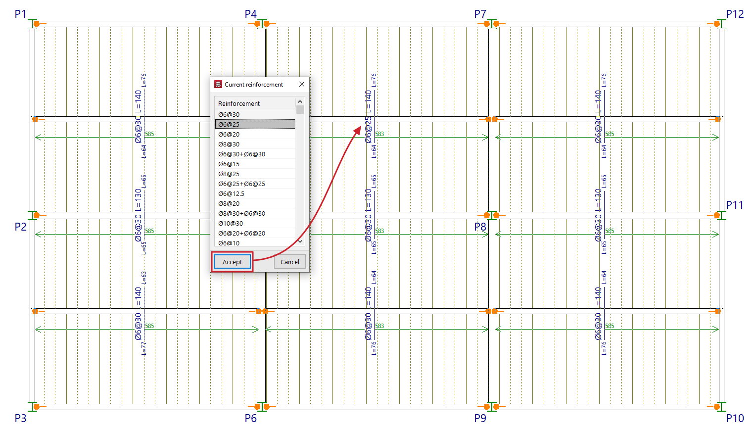
Assign
The "Assign" option allows you to change the diameters and spacing of the selected group of top reinforcement.
Right-clicking opens the "Current reinforcement" window, which allows you to select the reinforcement group to be assigned from those available in the top reinforcement table for composite slabs defined in the project.
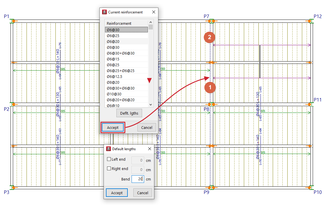
Enter
The "Enter" option allows you to insert top reinforcement bars on composite slabs.
When you click on the option, the pop-up window that appears when you right-click allows you to select the "Current reinforcement" from those available in the upper reinforcement table for composite slabs defined in the project. It is also possible to enter the "Default lengths" for the reinforcement to be placed, both at the left and right ends, as well as the length of the stirrup.
Next, left-click on two points on the plan view of a composite slab to position the reinforcement, either on both sides of an intermediate support (such as a beam), or near an edge support and at another point beyond the edge of the slab. In the box that appears, you will need to confirm the lengths of both ends, or of one of the ends and the length of the stirrup, as appropriate. The "Leng. betw." parameter indicates the distance between beam centres when inserting a continuous top reinforcement in a span. After accepting, the selected reinforcement will be drawn.
You cannot insert bars where reinforcement groups have already been defined: in this case, you must use the "Modify" option if you wish to add new bars or edit their data, or first delete the existing top reinforcement groups in order to use the "Enter" option.
Delete
The "Delete" option allows you to remove reinforcement bars from drawings.
To do this, the bars to be removed are selected using a selection box on the plan view.
Modify position
The "Modify position" option allows you to move the display of the flat sign from one bar to another point within the same bar. This can be useful when the flat sign label interferes with other text.
To change the position of the reinforcement display, click on the label text in the reinforcement slab width, then click on a point in the same slab width to define its new position.
Options for copying floor slabs
The following options are available in the "Slabs/Waffle slabs", "Joists", "Hollow core slabs" and "Composite slabs" on the "Results" tab, allowing you to save and retrieve copies of the slab reinforcement for all groups, or to copy slab reinforcement from one group to another.
Selecting these options only affects the type of floor slab in the relevant menu where they have been selected.
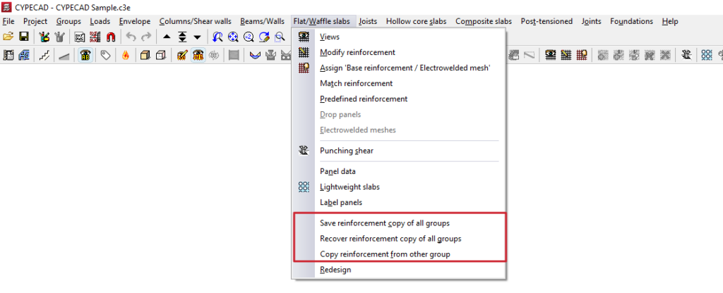
Save reinforcement copy of all groups / Recover reinforcement copy of all groups
These options allow you to save and restore backup copies of the reinforcement layout for the relevant type of floor slab in all groups, should it be necessary to redesign the structure, thereby preventing the loss of work carried out on the reinforcement.
The process is as follows:
- In a previously analysed project, the user makes manual modifications to the reinforcement in the parts of the model that require them.
- The "Save reinforcement copy of all groups" option is used to save the reinforcement with these modifications. Any modifications made to the reinforcement after this copy has been saved will not be saved.
- Subsequently, modifications are made to the projects that require a reanalysis (for example, by adding new elements to the structure).
- The project is reanalysed. During the reanalysis process, the program will have automatically made modifications to the floor structures of all groups, thereby losing the changes made manually.
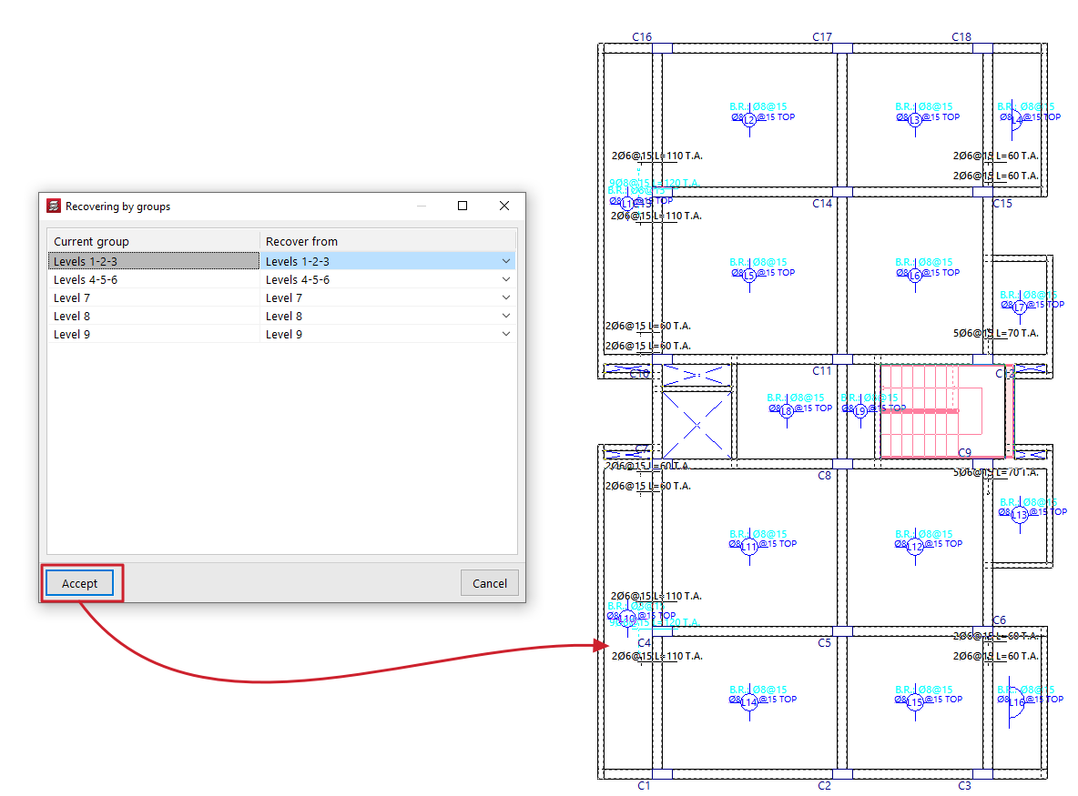
- At this point, use the "Recover reinforcement copy of all groups" option. In the window that appears, you must specify, for each ‘Current group’, the reinforcement you wish to restore (in the ‘Restore from’ column) from those available in the previous save.
Copy reinforcement from another group
This option allows you to copy the layouts from one group of floors to another.
This is particularly useful in cases where there are floors with identical layouts and loads: you would simply need to make the changes to the reinforcement for one of them, and then copy the reinforcement.
To make a copy, follow these steps:
- Firstly, you need to select the target reinforcement (the reinforcement into which you wish to copy the structure of another reinforcement).
- Next, click on the "Copy reinforcement from another group" option in the relevant menu.
- Next, in the window that opens, select the group of floors from which you wish to copy the layout.
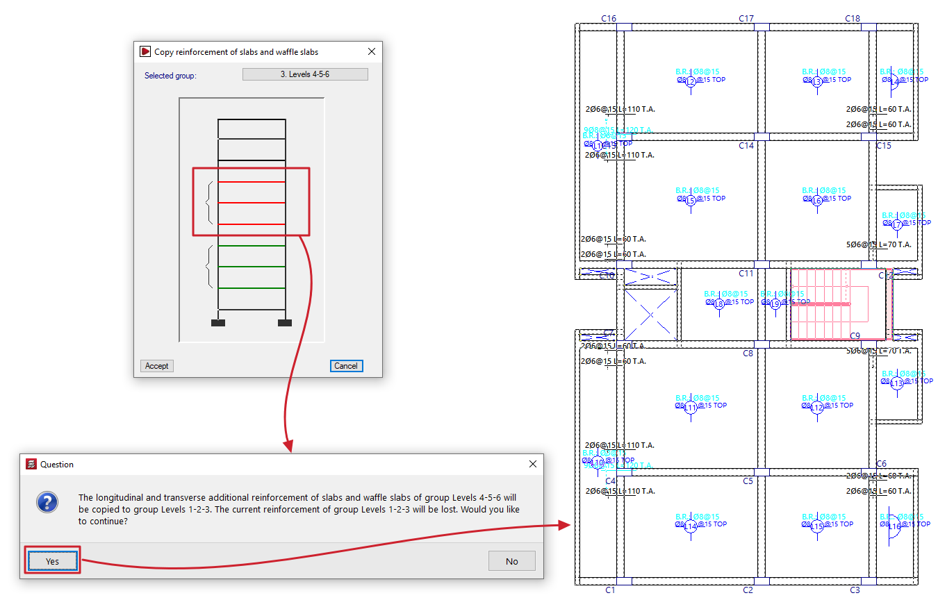
| Note: |
|---|
| If the target floor plan has a different layout from the standard floor plan, the reinforcement will only be copied in areas where there is a floor slab. In openings, the reinforcement is cut off, and no stirrups are placed. Furthermore, both the angle and the intersection point of the mesh must match. For this reason, when defining a group of floors, it is recommended to always copy the immediately preceding group. It is important to check any bars that have been cut, adding the corresponding stirrups or making any other necessary adjustments. |
Table of contents
Complete your tour of CYPECAD by exploring the other available sections:
- Introduction
- Introduction and creating new jobs
- General data configuration
- Defining floors and groups of floors and inserting columns, shear walls and starts ("Column input" tab)
- Inserting beams, walls, floor slabs, foundation elements and special elements, and structural analysis (the "Beam Input" tab):
- Checking analysis results and editing elements (the "Results" tab):
- Options on the "Contour plots" tab
- Printing documents and exporting data
- More information:
- General features of CYPECAD