Introduction
CYPEFIRE Pressure Systems is a program created for the design of pressure differential systems for the retention of fire smoke in non-airtight spaces in accordance with the European standard EN 12101-13.
The app can import the necessary information extracted from models developed in other Open BIM tools, such as the geometry of stairwell spaces, protected lobbies or lifts, which require an overpressure smoke control system.
Workflows supported by the program
As CYPEFIRE Pressure Systems is an Open BIM tool and is connected to the BIMserver.center platform, it offers the following workflow.
Data entry
Importing BIM models
If the CYPEFIRE Pressure Systems job is linked to a BIM project on the BIMserver.center platform, the following is possible:
- Importing the model with the geometry of a building. This makes it possible to generate the floor plan of the building, to import the layout of the spaces in the space and to assign space types (staircases, protected lobbies and lifts). Among the possible options are the following:
- Importing models designed in CYPE Architecture.
- Importing models designed in IFC Builder.
- Importing models in IFC format (generated by CAD/BIM programs such as Allplan, ArchiCAD and others) uploaded to the BIMserver.center project via the web platform.
- Importing models designed in Autodesk Revit with the Open BIM - Revit Plugin.
- Laying out model elements: model elements can be entered into CYPEFIRE Pressure Systems based on the imported geometry, by free input into CYPEFIRE Pressure Systems or based on DXF/DWG, DWF templates or images (.jpeg, .jpg, .bmp, .wmf).
Free data entry
If the CYPEFIRE Pressure Systems job is not linked to a BIM project on the BIMserver.center platform, the following is possible:
- Design and analysis of the differential pressure system by numerical entry of data in CYPEFIRE Pressure Systems ("Systems" option).
Data output
- Exporting reports to HTML, DOCX, PDF, RTF and TXT formats.
- Exporting drawings to DXF, DWG and PDF formats.
- Exporting the information contained in CYPEFIRE Pressure Systems to the BIMserver.center platform using IFC and glTF formats. This allows it to be viewed by authorised project participants.
Work environment
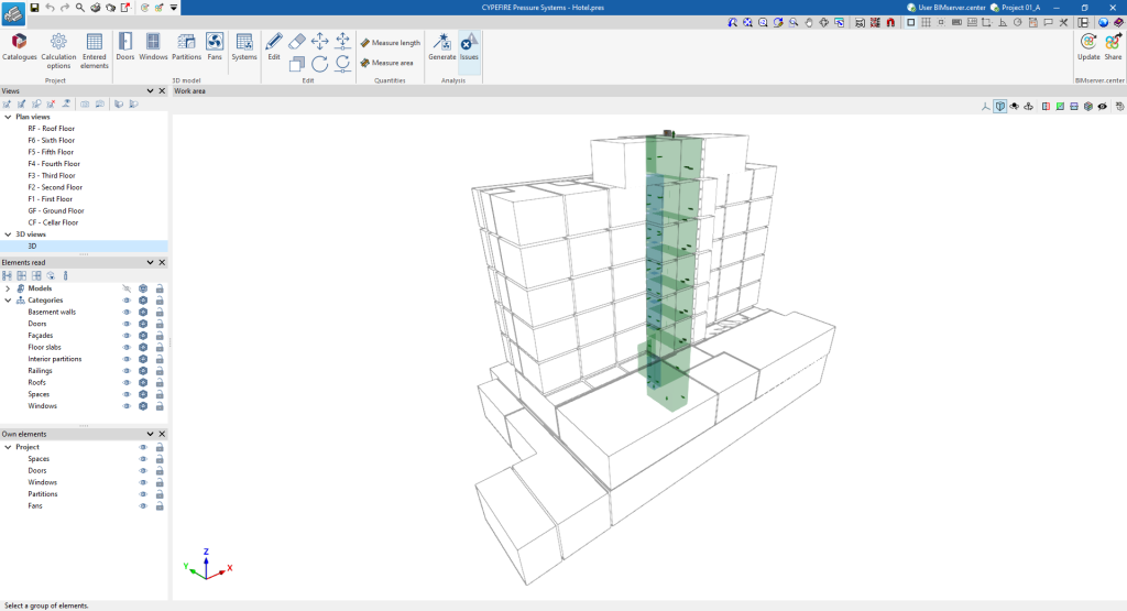
The CYPEFIRE Pressure Systems interface has a similar work environment to other CYPE tools and features a system of dockable windows that can be customised to adapt the workspace to the project's needs.
This environment allows the system's design to be carried out quickly and easily, both in a 3D view and in any type of 2D view (such as floor plans and elevations). This way, the elements in the system can be entered using the most appropriate view at any given time.
The tab shows the following:
- An upper toolbar containing the tools for: managing the general characteristics of the project; entering the air leaks and the elements of the installation; defining and generating the pressure differential systems; using the editing and measuring tools; and checking the installation.
- The modelling area, on the right-hand side of the screen, where all the elements of the project are entered, edited and displayed.
- On the left-hand side, there are several panels with tools to define the views of the project and to manage the visibility of the elements read and the own elements.
Input and output sequence for the design and analysis of pressure differential systems
The design and analysis of pressure differential systems in a building can be carried out in the program by means of the following input and output sequence:
- Creating of a new job (from "File", "New").
- Linking to BIMserver.centre, import of spaces by reference or type and assignment of space types.
- Loading manufacturer's catalogues (from "Project", "Catalogues").
- Reviewing general project options (from "Project", "Design options").
- (Optional) Reviewing the pressurisation conditions assigned to the imported spaces in the work area (from "Edit", "Edit").
- Arranging the air leaks corresponding to the construction elements and openings in the work area (from the options of the "3D Model" group: "Doors", "Windows" and "Partitions"). When entering the leaks, the reference of the pressure differential systems to which they belong is entered in the corresponding field.
- Generating pressure differential systems from the elements arranged in the work area (from "Calculation", "Generate"). By selecting the type of system, the program will collect all the leaks belonging to the same differential pressure system and create as many as it finds. As a consequence, the generated systems appear in the "3D Model", "Systems" table, collecting the updated information of the elements that are assigned to them.
- Selecting fans (from "3D Model", "Systems"). The selection of the fans is made by consulting the data calculated for the systems and will update the graphic information of the same.
- Arranging fans in the work area (from "3D Model", "Fans"). When entering the fans, the pressure differential systems to which they belong are selected in the corresponding field.
- Obtaining reports and drawings (from "File", "Reports/Drawings").
- Exporting to BIMserver.center (from "BIMserver.center", "Share").
Examples of differential pressure system models
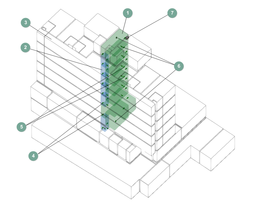
A model of a differential pressure system that can be developed in the program is shown below, indicating the layout of the elements, as well as the options that allow them to be entered into the model:
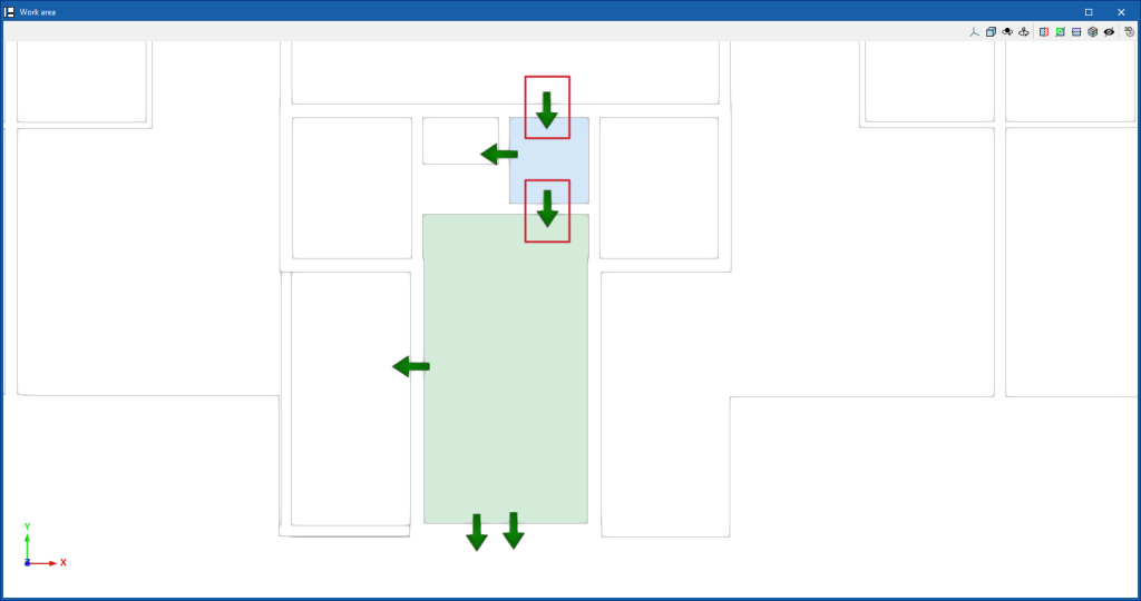
Differential pressure system for hotel stairs
- Pressurised spaces: stairs (import and assignment from the spaces in the BIM model when creating a new job or from "BIMserver.center", "Update").
- Pressurised spaces: protected lobbies (importing and assigning from the spaces in the BIM model when creating a new job or from "BIMserver.center", "Update").
- Unpressurised spaces (importing and assigning from the spaces in the BIM model when creating a new job or from "BIMserver.center", "Update").
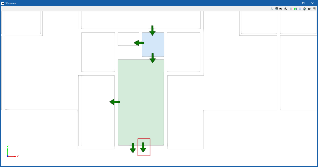
- Air leaks corresponding to doors (from "3D model", "Door").
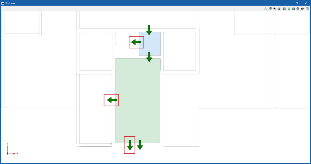
- Air leakage for windows (from "3D model", "Window").
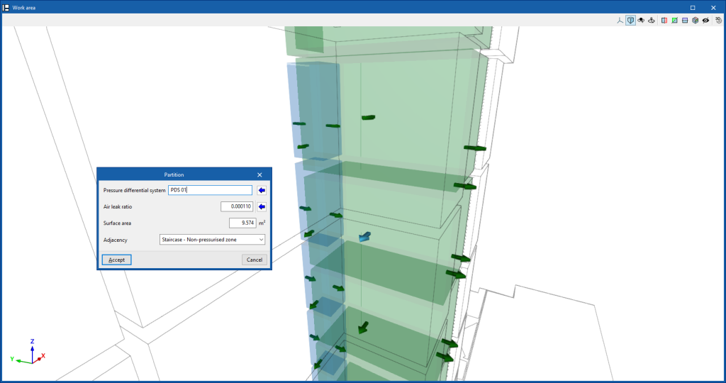
- Air leakage corresponding to horizontal and/or vertical partitions (from "3D Model", "Partition").
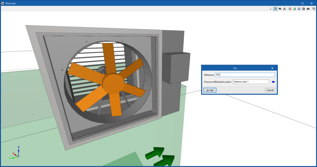
- Fan (from "3D Model", "Fan").
Creating a new job, linking to a project and importing data
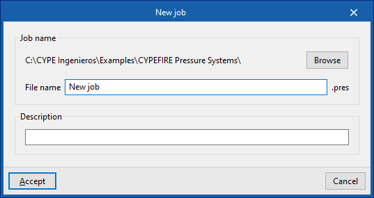
When starting the application and clicking on "New", a "New job" can be created. After entering the "File name" and "Description", the job can then be integrated into an existing project in BIMserver.center.
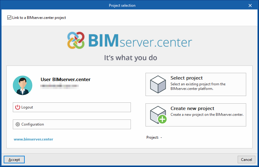
This is done in the "Project selection" window, which contains the following options:
- On the left-hand side, you can log in with a BIMserver.center account.
- On the right-hand side, the "Select project" option is used to choose an existing project. It is also possible to "Create a new project". In this case, the created project will be visible from BIMserver.center from that moment on.
- There is the option to start the project without being linked to the BIMserver.center platform. To do this, simply uncheck the "Link to a BIMserver.center project" box at the top left.
Once the new job has been created, the general interface of the program is accessed. At any time while working, project files can be shared or imported via the "BIMserver.center" group, located at the top right of the general interface.
Importing BIM models
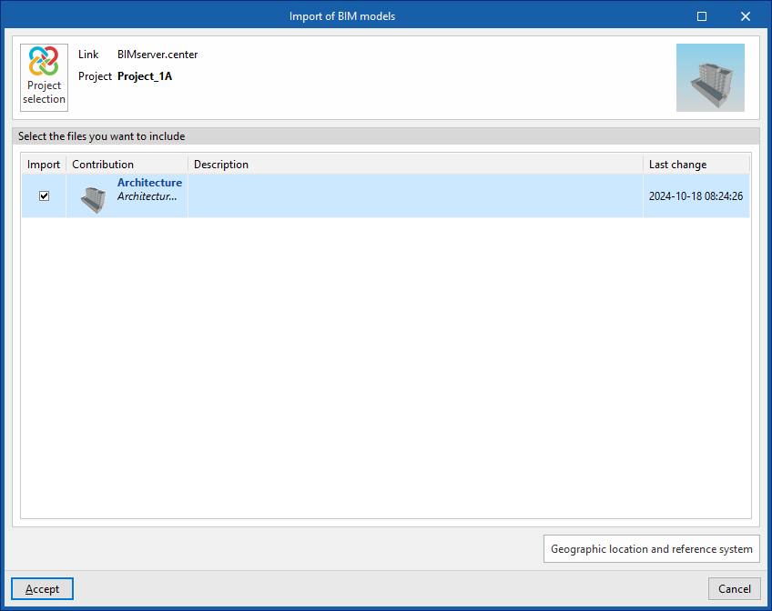
When creating a new job and selecting a project hosted on the BIMserver.centre platform from "Select project", the "Import BIM models" window appears, which shows the files contained in that project in IFC format.
The app offers the possibility of including one or more of the existing models in the project. To do this, check the "Import" box and accept it.
When accessing the interface, the graphic window will display the imported models. In addition, if they contain this information, the plan views necessary for the development of the installation model will be imported and created.
Classifying spaces
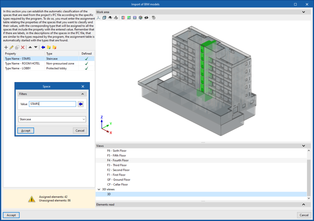
In the window that appears later in the BIM model import process, the automatic classification of the spaces read from the IFC file of the project can be established according to the specific types required by the program, such as the following:
- Non-pressurised zone
- Staircase
- Protected lobby
- Lift
To do this, entries must be added to the assignment table. In each entry, the spaces to be classified are filtered by indicating the values of their properties, and the type of space to be assigned to them from the program is selected.
The wizard in the top toolbar can also be used to perform a joint import of all the spaces read from the IFC file according to the desired property, which generates a table entry for each group of spaces of the same property.
The program displays the layout of the selected spaces in the model on the right-hand side.
Spaces that you do not want to include in the model should be deleted in this classification table.
The program shall assign the selected space type to all the spaces read from the IFC file that have the value indicated in the displayed property and generate their geometry, and then incorporate them into the model view.
Tools for managing manufacturer catalogues
In the "Project" group of the main toolbar there is an option to manage the manufacturer product catalogues in order to incorporate them into the project:

Catalogues
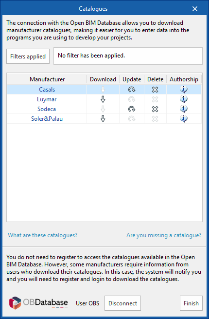
Downloads manufacturer catalogues using the connection to the Open BIM Database, which makes it easier to enter data into the program for project development.
Clicking on this option opens a window with the available manufacturer catalogues.
The "Filters applied" option allows users to apply filters so that only the desired manufacturers are displayed.
Downloading catalogues
The following options are shown for each manufacturer:
- Download
Download the manufacturer's catalogue. The products in the catalogue will be available in the project. - Update
Updates the selected manufacturer's catalogue to the latest version and deletes the downloaded version in the project. - Delete
Deletes the selected manufacturer's catalogue. The products in the catalogue are no longer available in the project.
Connection to Open BIM Database
At the bottom of this dialogue box, users can log in with their Open BIM Database account and password.
This also makes it possible to request new catalogues in case the program does not offer the desired catalogue. The request can be made using the form that opens when you click on the corresponding option ("Are you missing a catalogue?").
Configuring the calculation options
In the "Project" group in the main toolbar, there is an option to configure the project design options:

Calculation options
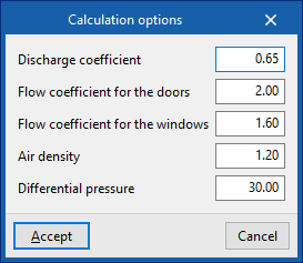
The main parameters for the design of the differential pressure system can be edited, such as air density and target pressure, as well as the different coefficients for calculating air leakage through doors, windows and building elements:
- Discharge coefficient
- Flow coefficient for the doors
- Flow coefficient for the windows
- Air density
- Differential pressure
Managing entered elements
The "Project" group in the main toolbar contains the option to manage the elements entered in the project:

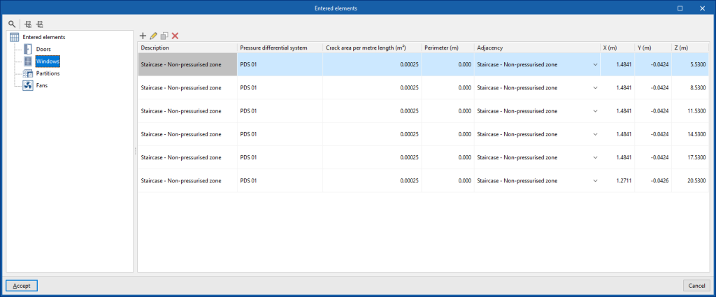
Entered elements
Users can consult and edit the data of each of the elements entered in the model, such as their characteristics, their 3D layout and the associated differential pressure system, in the following tables:
- Doors (Differential pressure system, Leakage area, Surface, Adjacency, 3D layout (X, Y, Z))
- Windows (Description, Differential pressure system, Crack area per metre length, Perimeter, Adjacency, 3D layout (X, Y, Z))
- Partitions (Description, Differential pressure system, Air leakage rate, Area, Adjacency, 3D Layout (X, Y, Z))
- Fans (Reference, Differential pressure system, 3D layout (X, Y, Z))
By selecting several cells in the same column it is possible to edit them simultaneously, after entering the parameter value.
Entering elements in the 3D model: doors, windows, partitions and ventilators
The "3D model" group in the main toolbar contains the options for inserting elements into the 3D model, such as air leaks for doors, windows and partitions, as well as fans:

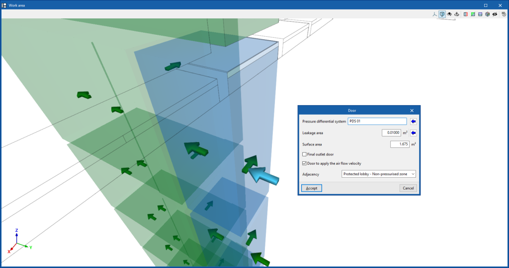
Door
Inserts the air leakage of a door.
These elements may be arranged in the position of doors separating stairways, protected lobbies or lifts from non-pressurised areas (including the external space), or in the position of doors allowing passage between protected lobbies, lifts or stairways.
When entering or editing one of these elements, the program allows the following parameters to be defined:
- Pressure differential system
Selects the pressure differential system associated with the element. The button on the right allows the selection of a system from those defined in "3D Model", "Systems". - Leakage area
Enters the leakage area of the element. The button on the right imports the value for different usual door cases (such as single leaf, double leaf or lift floor doors). - Surface area
Door surface area. - Final outlet door (optional)
Activating this option indicates that the element is a final outlet door, e.g. the outlet door of a stairwell on the ground floor. - Door to apply the air flow velocity (optional)
- Adjacency
- Selects the pair of space types that separate and adjoin the door, e.g. a staircase and a non-pressurised zone.
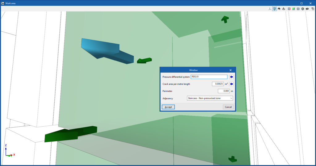
Window
Enters the air leakage from a window.
These elements may be arranged in the position of windows separating stairways, protected lobbies or lifts from non-pressurised areas (including outdoor space).
When entering or editing one of these elements, the program allows the following parameters to be defined:
- Pressure differential system
Selects the pressure differential system associated with the element. The button on the right is used to select a system from those defined in "3D Model", "Systems". - Crack area per metre length
Enters the area or surface of cracks per metre length. The button on the right is used to import the value for different usual cases of windows (such as pivot or sliding windows). - Perimeter
Enters the value of the window perimeter. - Adjacency
- Selects the pair of space types separating the window and adjoining the window, e.g. a staircase and a non-pressurised area (such as an outdoor space).
Partitions
Enters the air leakage of a partition (vertical or horizontal).
These elements may be arranged in the position of horizontal or vertical partitions separating stairways, protected lobbies or lifts from non-pressurised areas (including outdoor space), whether facades, interior partitions, floor slabs or roofs.
When entering or editing one of these elements, the program defines the following parameters:
- Differential pressure system
Selects the differential pressure system associated with the element. The button on the right allows the selection of a system from those defined in "3D Model", "Systems". - Air leak ratio
Enters the air leakage rate of the element. The button on the right allows importing the value for different usual cases of partitions (such as external walls, internal and staircase walls, lift shaft walls or floors). - Surface area
Enters the area or surface area of the partition. - Adjacency
- Selects the pair of space types separating the partition and adjoining the partition, e.g. a staircase and a non-pressurised zone.
Fans
Inserts the fans of the overpressure system.
When entering or editing one of these elements, the program defines the following parameters:
- Reference
Fan reference. - Pressure differential system
Selects the pressure differential system associated with the element. The button on the right is used to select a system from those defined in "3D Model", "Systems".
Defining pressure differential systems
Within the "3D Model" group in the main toolbar, there is an option to define pressure differential systems:

Systems
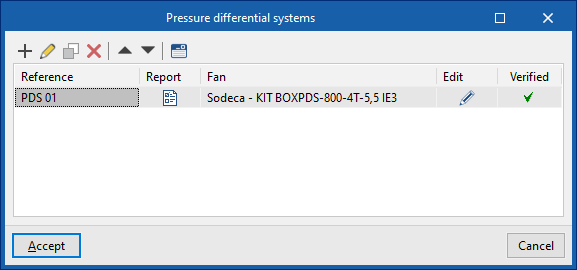
This opens the "Pressure differential systems" window. In the table that appears, pressure differential systems can be created, edited, copied, deleted and reordered.
The systems generated using the "Generate" option in the "Analysis" group are also displayed here.
-Automatically generating the pressure differential systems from the elements arranged in the work area. In this case, the reference of the systems (not yet defined in the "3D Model", "Systems" table) can be written directly in the elements of the model. Then, from "Analysis", "Generate", the systems can be generated from the information entered in the elements. The generated systems appear in the "3D model", "Systems" table as a consequence, with the updated information of the elements that are assigned to them.
-Manually defining pressure differential systems and updating them based on the elements arranged in the work area. The systems can first be created in the "3D model" table, "Systems". This can be done in a simplified form using the corresponding option ("Simplified entry of a pressure differential system"). Subsequently, the systems are assigned to the elements arranged in the model by editing them ("Edit", "Edit"). Later, the "Generate" option in the "Calculation" group can be used to update the required information in the "Systems" table.
-Defining pressure differential systems numerically. Systems can also be created and defined directly using the "3D model", "Systems" table, by entering all data numerically, without elements arranged in the work area and therefore without the geometry of spaces and the linking to a BIM model. As in the previous point, this can be done simply by using the corresponding option ("Simplified entry of a pressure differential system").
Pressure differential systems
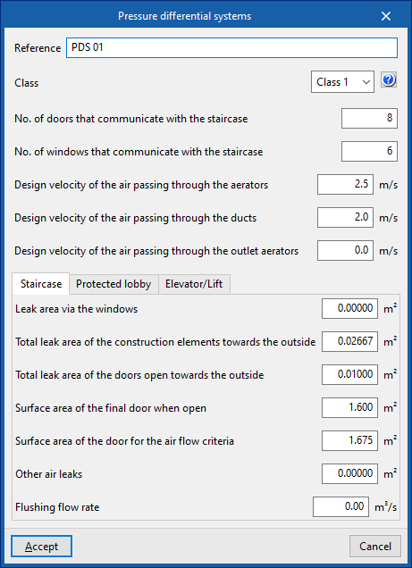
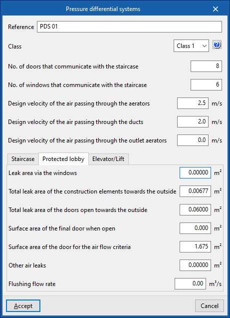
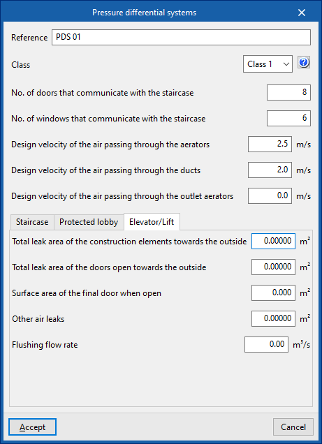
When creating or editing a pressure differential system, the following parameters need to be configured.
These parameters are generated automatically by using the "Generate" option in the "Calculation" group, and are filled in from scratch when creating the system in case of using the "Generate all systems" option, or by updating their values in case of using the "Generate incorrect systems only" option.
- Reference
- Class (Class 1 / Class 2)
- No. of doors that communicate with the staircase
- No. of windows that communicate with the staircase
- Design velocity of the air passing through the aerators
- Design velocity of the air passing through the ducts
- Design velocity of the air passing through the outlet aerators
"Staircase" tab
Defines the parameters associated with the staircase:
- Leak area via windows
- Total leak area of building elements towards the outside
- Total leak area of doors open towards the outside
- Surface area of the final door when open
- Surface area of the door for the air flow criteria
- Other air leaks
- Flushing flow rate
"Protected lobby" tab
Defines the parameters associated with the protected lobby:
- Leak area via windows
- Total leak area of building elements towards the outside
- Total leak area of doors open towards the outside
- Surface area of the final door when open
- Surface area of the door for the air flow criteria
- Other air leaks
- Flushing flow rate
"Lift" tab
Defines the parameters associated with the lift:
- Total leak area of building elements towards the outside
- Total leak area of doors open towards the outside
- Surface area of the final door when open
- Other air leaks
- Flushing flow rate
Simplified entry of a pressure differential system
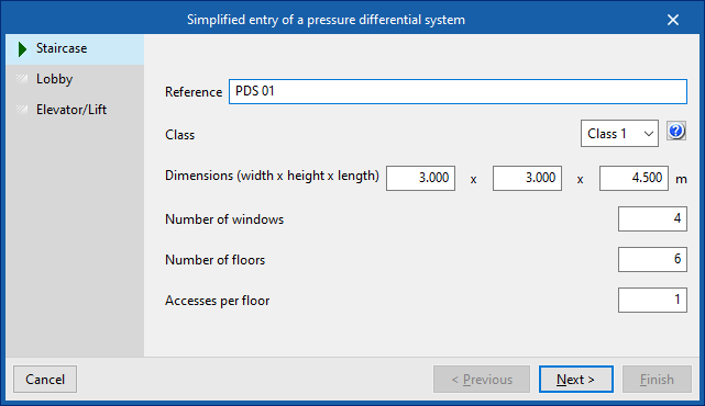
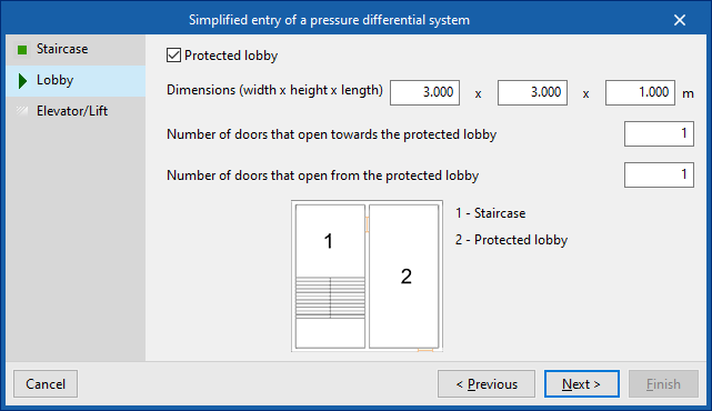
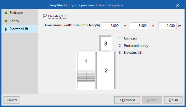
This option, located above the table in the "Pressure differential systems" window, opens a wizard that allows you to generate a pressure differential system by entering your data in a simplified form, indicating the parameters of the staircase, the protected lobby and the lift, where present.
Staircase
- Reference
- Class (Class 1 / Class 2)
- Dimensions (width x height x length)
- Number of windows
- Number of doors
- Accesses per floor
Lobby
- Protected lobby (optional)
- Dimensions (width x height x length)
- Number of doors that open towards the protected lobby
- Number of doors that open from the protected lobby
Lift
- Lift (optional)
- Dimensions (width x height x length)
When the wizard has finished, the pressure differential system will be created and displayed in the table. Users can edit the parameters of this system freely if necessary.
Fan selection
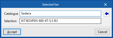
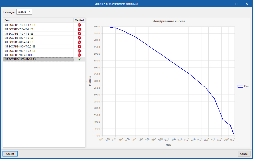
For each system, the program selects a fan that meets the minimum requirements of the assigned pressurisation system using the option available in the "Edit" column.
- Catalogue
- Selection
The button on the right selects a fan from the available manufacturer catalogues. These catalogues can be loaded from the "Catalogues" option in the "Project" group in the program's general interface.
The "Fan" column shall show the fan reference of the selected fan.
The "Complies" column shall indicate whether the selected fan complies with the specifications required by the system.
On the right, the curve relating the flow rate and the fan operating point pressure is shown.
If a fan is available in the model and assigned to the system, its representation will be updated after the fan has been selected. If not, the fan can now be arranged via the "Fan" option in the "3D model" group by selecting the corresponding system.
Editing tools
In the "Edit" group of the main toolbar, there are editing tools:

These options are used to perform the following editing operations on the elements entered in the model:
| Edit | Edits the parametric properties of the selected element in the model. | |
| Delete | Deletes a previously entered element. | |
| Copy | Creates a copy of one or more elements. | |
| Move a group of elements | Moves a group of elements. | |
| Rotate a group of elements | Rotates a group of elements around the axis defined by two points. | |
| Move | Moves an element or a node of an element. | |
| Rotate | Rotates an element around the axis shown when using the option. |
Quantities tools
In the "Quantities" group of the main toolbar, there are measurement tools:

These options allow the following measurement operations to be performed on the elements entered in the model:
| Measure length | Measures lengths between defined points on the model. | |
| Measure area | Measures areas defined by points entered in the model. |
Tools in the "Analysis" group
The following options are available in the "Analysis" group of the main toolbar:

Generate
Generates or updates pressure differential systems of the model from the data defined in the elements entered in the 3D model (doors, windows and partitions).
The program examines the "Pressure differential system" fields, available in the editing panel of these elements, and creates or updates the system information based on them.
One of the following generation options can be selected:
- Generate only the incorrect systems
If this option is selected, only the information of systems with errors is updated. Generation of non-existing systems is also performed. - Generate all systems
If this option is selected, the generation of all systems in the model is performed and any previously entered systems are deleted.
In addition, the class of the systems to be generated must be selected:
- Class (Class 1 / Class 2)
The result is the updating or generation of pressure differential systems, assigning them the selected class. The information on the generated or updated systems can be consulted using the "Systems" option in the "3D Model" group.
Issues
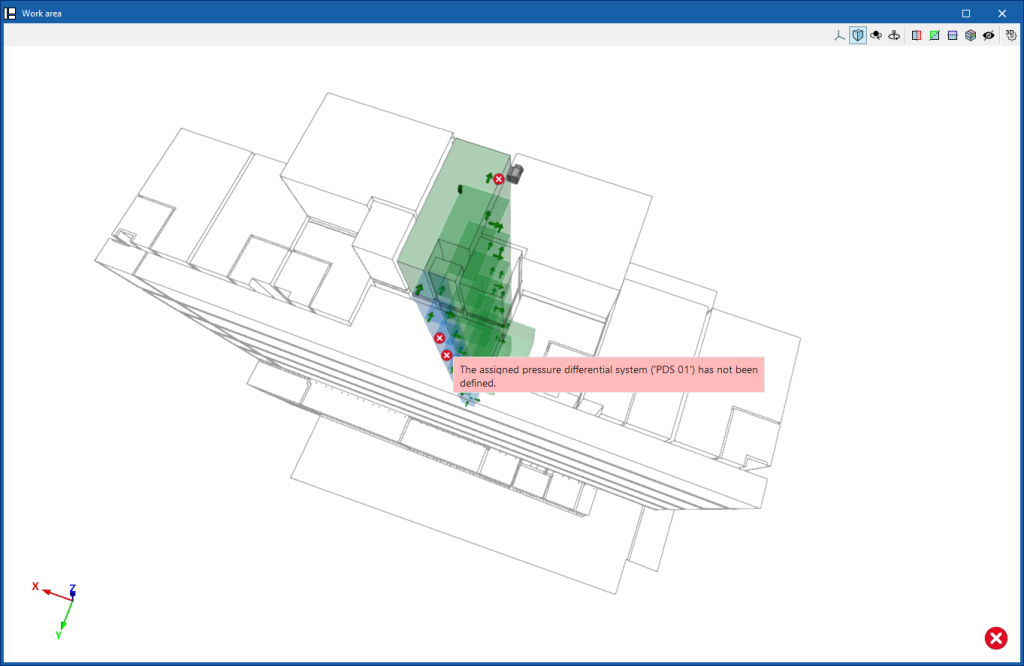
If this option is activated, the elements where an error has occurred are highlighted. By positioning the cursor on these elements, the message describing the error can be displayed.
Some of these issues can be corrected by using the "Generate" option to perform an update of the systems that have elements with errors assigned to them, by selecting "Generate only incorrect systems".
Results output
Reports
The program can print the reports directly or generate HTML, PDF, TXT, RTF or DOCX files.
The job's reports, with information on all the systems entered, are obtained via the "Reports" option in the "File" menu or from the top left-hand side of the interface.
The individual justification report for each system can also be printed via the "Systems" option in the "3D Model" group, using the option in the "Reports" column.
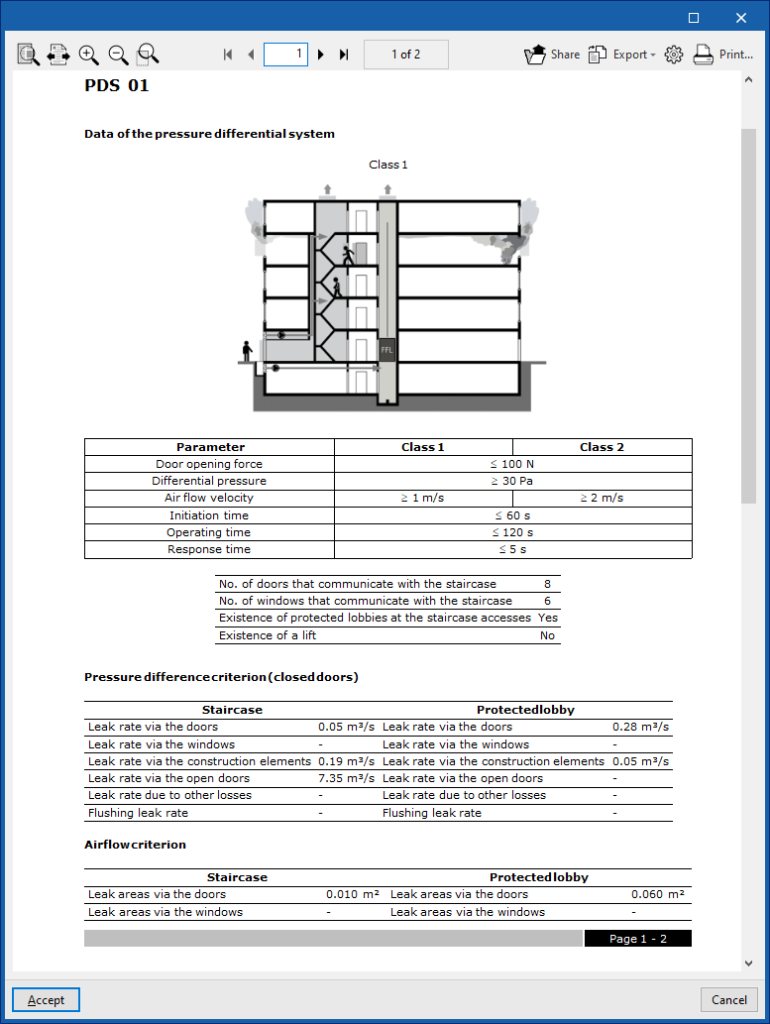
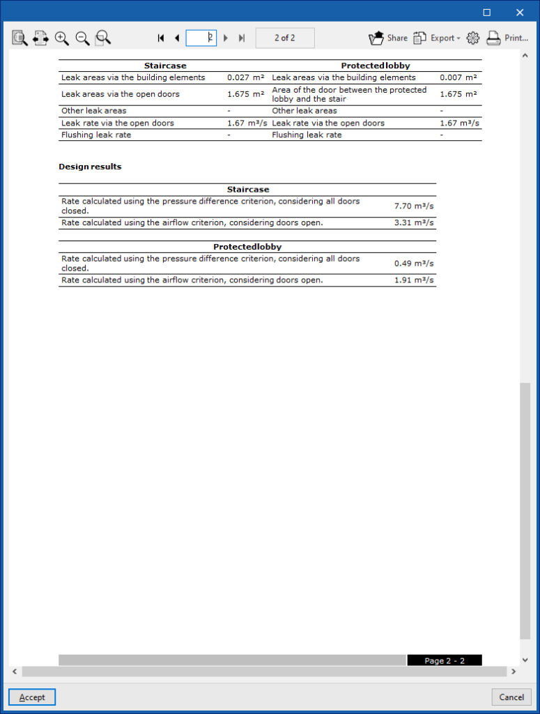
These reports show the following information for each pressure differential system. The types of systems, the estimated leakage through doors, windows and partitions and the flow rate obtained for each of the calculated criteria are detailed:
- Pressure differential system data
- Pressure differential criteria (doors closed)
- Air flow criteria
- Analysis results
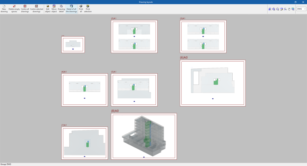
Drawings in DWG, DXF or PDF format
The program can print the job drawings on any graphic peripheral configured on the computer, or create DWG, DXF or PDF files.
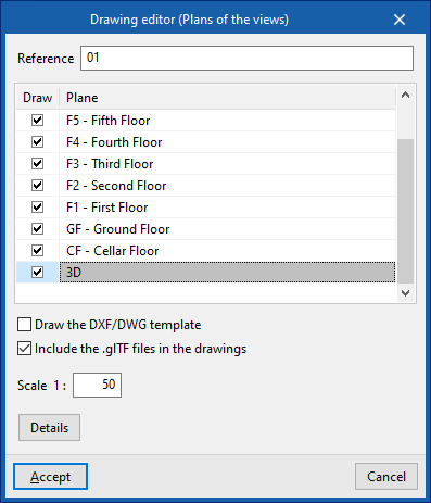
The following options can be configured when editing the drawing:
- Reference
- Views to be drawn
- Drawing DXF/DWG template (optional)
- Include .glTF files in the drawings (optional)
- Scale
- Details
The drawings can be obtained using the "Drawings" option in the "File" menu or from the top left-hand side of the interface.
GLTF file compatible with BIMserver.center
When a project is exported to the BIMserver.center platform, a 3D model is automatically exported in GLTF format for the integration of the installation model in the Open BIM project, allowing it to be viewed:
- on the online platform;
- in the BIMserver.center app for iOS and Android;
- in virtual reality and augmented reality;
- in other CYPE programs.
Integration into the BIMserver.center platform
Many of CYPE's programs are connected to the BIMserver.center platform and allow collaborative work to be carried out via the exchange of files in formats based on open standards.
Please note that, to work on BIMserver.center, users can register on the platform free of charge and create a profile.
When accessing a program connected to the platform, the program connects to a project in BIMserver.center. This way, the files of the projects that have been developed collaboratively in BIMserver.center are kept up to date.

Options available in CYPEFIRE Pressure Systems
The "BIMserver.center" group in the main toolbar contains the features required to use CYPEFIRE Pressure Systems together with other BIMserver.center tools:

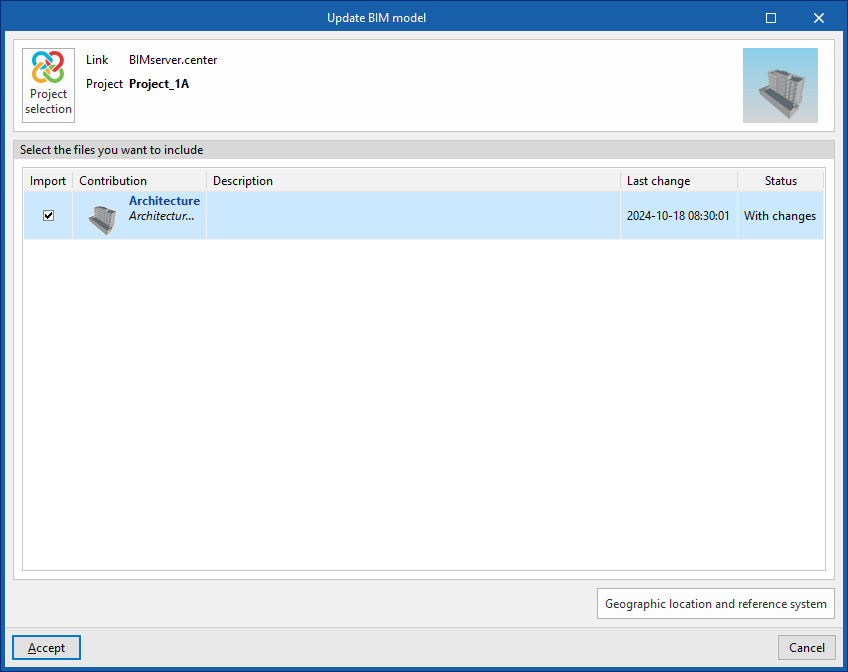
Update
Updates information contained in models previously imported into the project or imports new models, if desired.
In the updating process, just like in the process of creating a new job, the spaces in the BIM model can be read and assigned to one of the available types of spaces. This way, the program generates the spaces automatically or updates them according to the latest changes.
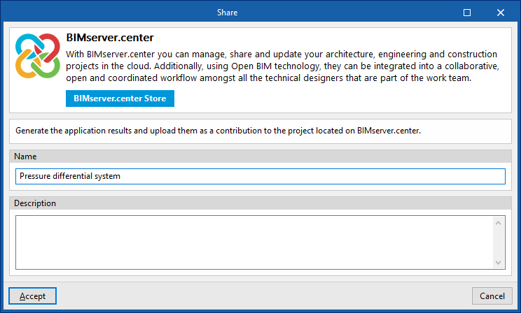
Share
Exports the installation information developed with CYPEFIRE Pressure Systems to BIMserver.center to share it with other users, including the quantities reports and the system design.
During the export process, information related to the identification of the files to be exported can be defined:
- Name
- Description
Licenses and related modules
CYPE programs are activated via electronic licenses which may contain one or more modules. The list of modules compatible with each program may vary depending on the product purchased and the type of license.
To consult the list of modules compatible with this program, go to "CYPE program modules".
Please note that the list of modules available in the license will depend on the product purchased.


