
Workspace
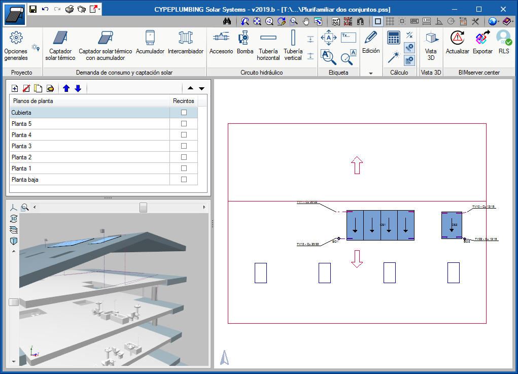
The program has been designed for users to work in a 2D workspace with the possibility to view the 3D view of the installation that has been entered, in real time.
The design of the system can be carried out on 2D templates from the BIM model using IFC files or DXF-DWG, DWF files or images (.jpeg, .jpg, .bmp, .wmf), which can be included in the program.
Users can work, by layers, on the different networks that the program allows them to design:
- Supply water network
- Return water network
- Auxiliary supply water network
- Auxiliary return water network
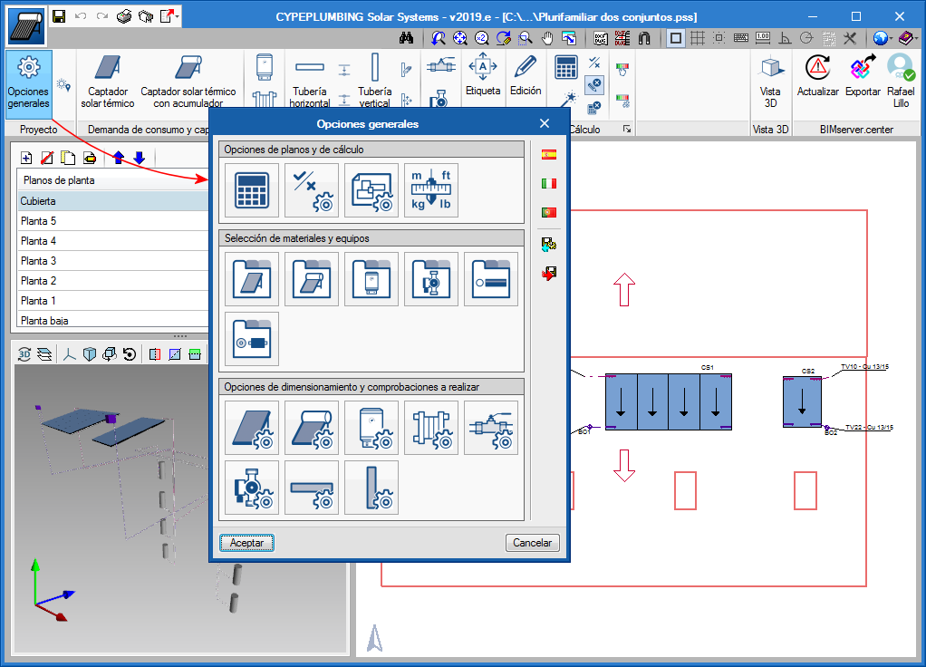
Program settings
In the "General settings" dialogue box, users can establish the basic data to enter and design the installation: Code selection, Analysis and drawing options, Material and equipment selection, and Design and check options to be carried out.
Code selection
CYPEPLUMBING Solar Systems designs the installation in accordance with the selected code and with customised design configurations of other codes or custom technical configurations. The design codes that are currently implemented in the program are:
| Country | Code |
 | CTE DB HE 4 |
 | REH |
 | UNI/TS 11300-4 |
 | Configurable codes |
Depending on the country from which the licensee acquires the license, only the codes for that country will be activated. More information on this aspect and on acquiring codes that are not initially included can be found in the "Programs and design codes included in the user license" section of the Design codes implemented in CYPE programs webpage.
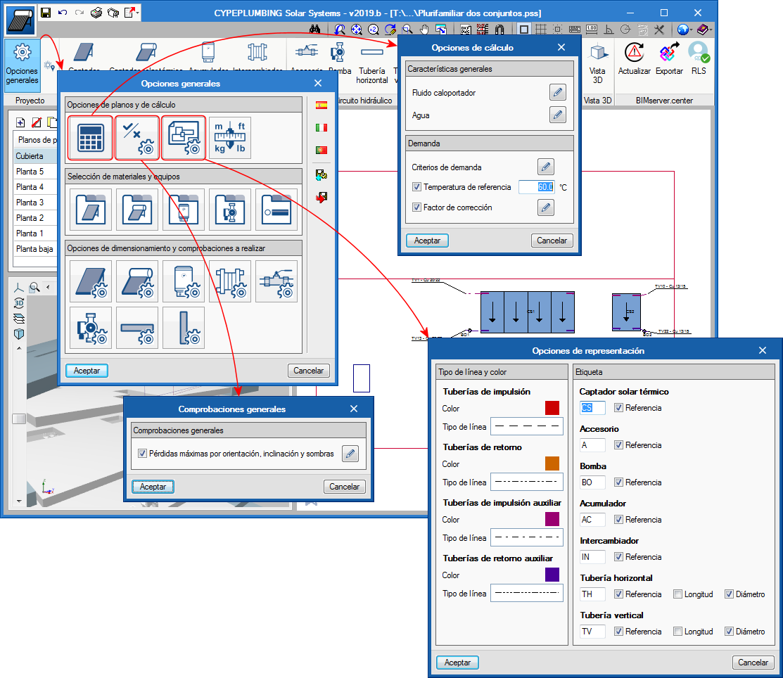
Analysis and drawing options
CYPEPLUMBING Solar Systems designs the thermal installation using the F-Chart method and performs the hydraulic analysis, using the "Darcy and Weisbach" formulas, and calculates the friction factor using the "Colebrook and White" equation.
Users can define a general configuration for drawings. It is possible to choose the type of line to be used for the pipes of the installations, the colour of the layers that contain them, the symbols to be applied and the references that are to be printed in the floor plans.
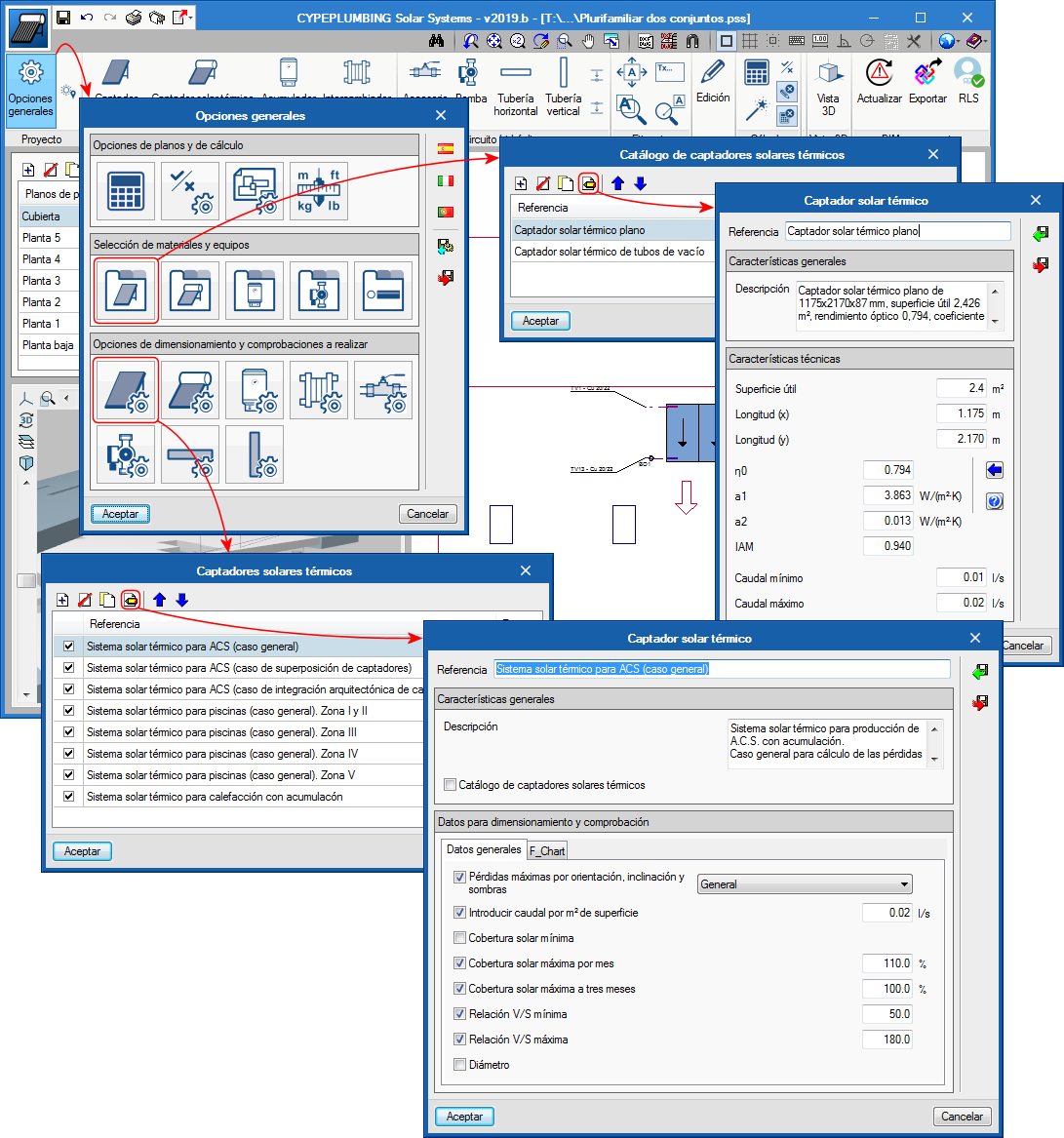
Material and equipment selection
The program contains predefined equipment catalogues to develop the installations and also allows users to define their own customised catalogues.
Design options and checks to be carried out
CYPEPLUMBING Solar Systems allows users to configure the analysis and the checks that have to be carried out on any element of the installation: solar thermal collectors with or without storage tanks, storage tanks, heat exchangers, accessories, pumps, horizontal and vertical pipes...
Analysis and checks
The program designs the networks in accordance with the selected code or customised configuration, and carries out the corresponding checks.
The installation network is analysed using gross flows.
CYPEPLUMBING Solar SYSTEMS automatically designs the hydraulic installation in the building. The program takes into account the checks that are defined in the "Design options and checks to be carried out" section. It can also perform a partial analysis, of each element of the installation. Using message alerts, the program will warn users whether codes are not complied with or if there are any installations that have been developed incorrectly, as an aid for their correct configuration.
The results can be viewed on the elements themselves and in the check reports that are generated by the program.
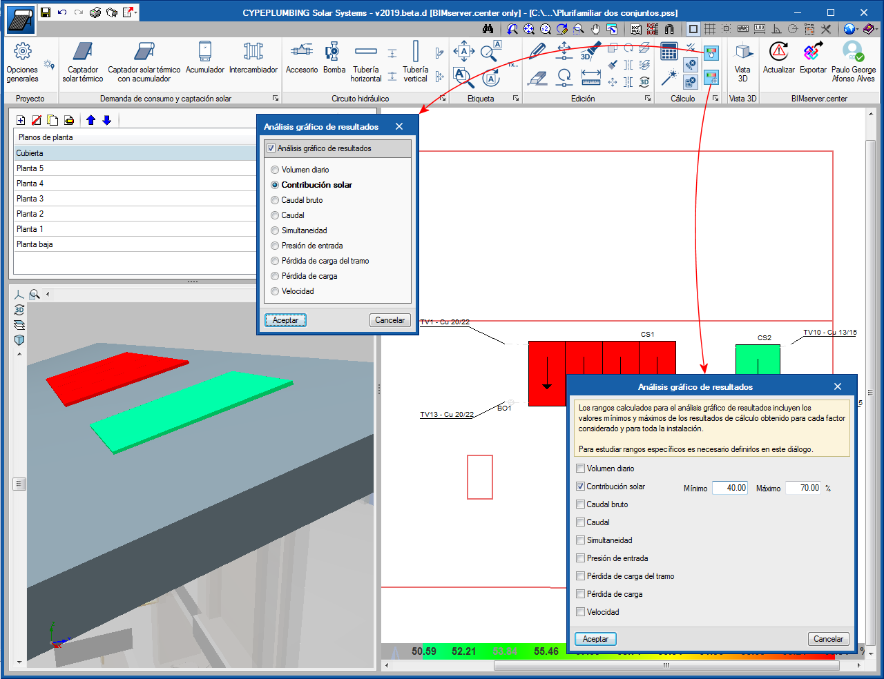
Graphical analysis of the results
One of the features that greatly helps users to analyse the results is the "Graphical analysis of the results".
CYPEPLUMBING Solar Systems allows users to select the parameters that intervene when calculating the demand, solar contribution and hydraulic design of the installation that is to be analysed and displays the installation with an applied colour scale so users can carry out a graphical analysis in the 2D and 3D screen views.
Users can also study specific result ranges for the complete installation.
Documents
As well as the on-screen results and their analysis possibilities, the program generates:
- Drawings
CYPEPLUMBING Solar Systems generates floor plan drawings, which can be printed or exported from the program to different formats (DXF, DWG, JPG, EMF, BMP). - Reports
The program generates reports of the checks, results and quantities that can be printed directly from the program or exported to different formats (TXT, HTML, RTF, DOCX, PDF).
The obtained quantities can be exported to the standard interchange format, FIEBDC 3, so it can be used in cost management programs. - Export to the BIM project
CYPEPLUMBING Solar Systems exports the documents that are generated and the 3D view of the installation to the BIM project that is located on the BIMserver.center platform, so they can be consulted by all the technical users that intervene in the project.