
Introduction
Portal frame generator is a program that automatically generates the geometry and loads of a parallel portal frame structure and exports the data to CYPE 3D, where the complete model is analysed.
Users can enter single or multiple portal frames, either mono pitch or dual pitch, rigid portal frames, or trusses. Wind and snow loads are calculated according to the selected standard and data.
In addition, the analysis and design of the steel purlins of the roof and the sides of the façade can be carried out, optimising the section and its spacing, as well as obtaining a design report with the data entered and the results obtained.
Finally, the frame geometry and the loads generated are exported to the CYPE 3D program, which greatly facilitates the data entry process for this type of structure. Surface loads are generated with the self-weight of the purlins and the defined envelopes, the service and snow loads of the roof and the wind loads for the roof, sides and lateral walls, as well as the loads associated with all of them.
Workflows supported by the program
Portal frame generator offers the following workflow:
Data entry
- Defining the geometry of the structure's frames in Portal frame generator.
- Defining, analysing and designing the purlins on the roof and sides of the structure in Portal frame generator.
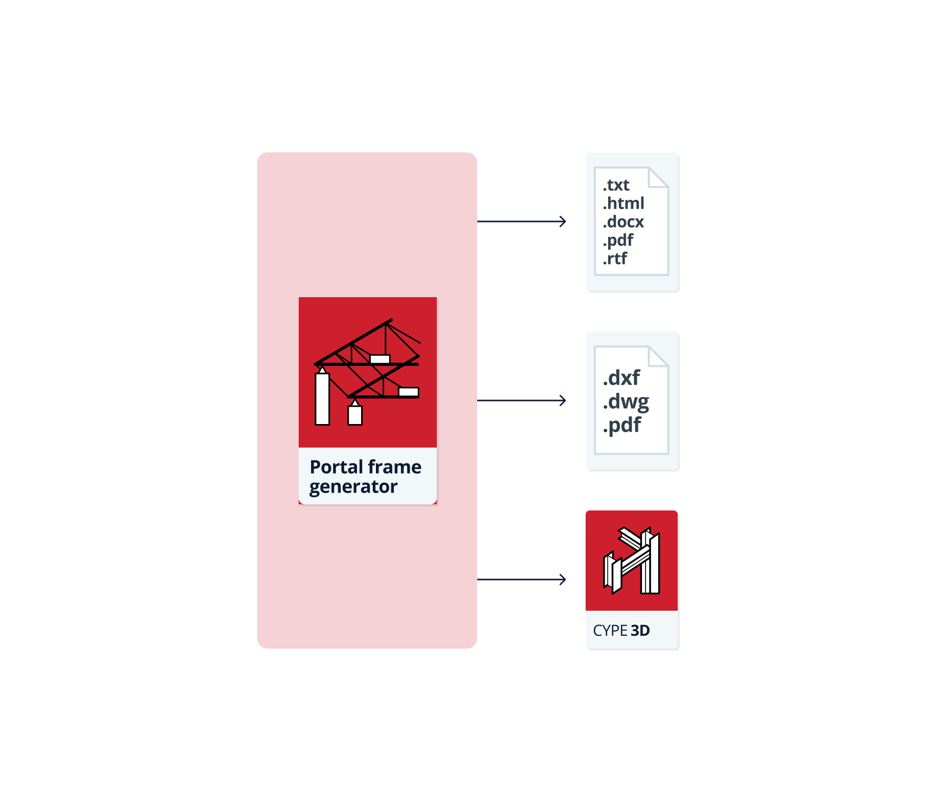
Data output
- Exporting reports with the data entered, the loads generated and the calculations of the purlins to HTML, DOCX, PDF, RTF and TXT formats.
- Exporting the drawing of the portal frame group entered to DXF, DWG and PDF formats.
- Exporting to CYPE 3D. This allows the geometry of the portal frame structure and the loads and loadcases to be automatically generated in CYPE 3D from the information defined in Portal frame generator, as well as the external links of the columns and the buckling lengths of the bars. Later, in CYPE 3D, the corresponding adjustments can be made to complete the design of the structure and carry out its analysis, checks and design.
Work environment
The program has a simple work environment that can be used to quickly enter and edit portal frame geometry in the available work area:
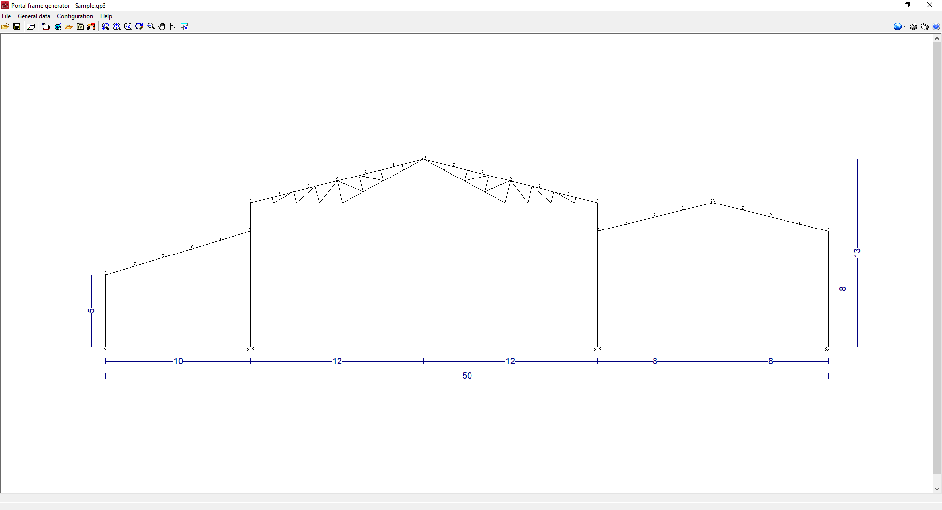
The interface displays the following:
- The menus at the top, where there are tools for:
- accessing the "File" menu;
- accessing the "General data" menu, which allows:
- seting up the general data of the job;
- editing the purlins on the sides and roof of the structure;
- seting up the display options for the purlins, loads and/or dimensions;
- managing the profile library;
- managing the user steel library;
- and exporting to CYPE 3D;
- accessing the "Configuration" menu, which contains the general configuration options, including the selection of the material standard and the units to be used;
- and accessing the "Help" menu.
- An auxiliary horizontal bar, under the menus at the top, where there are shortcuts to the tools for:
- opening the file manager and save the job;
- accessing the different options in the "General data" menu;
- setting the work area view or print the current view;
- accessing the general configuration options, equivalent to those in the "Configuration" menu;
- printing the reports and drawings of the job;
- and accessing the available help.
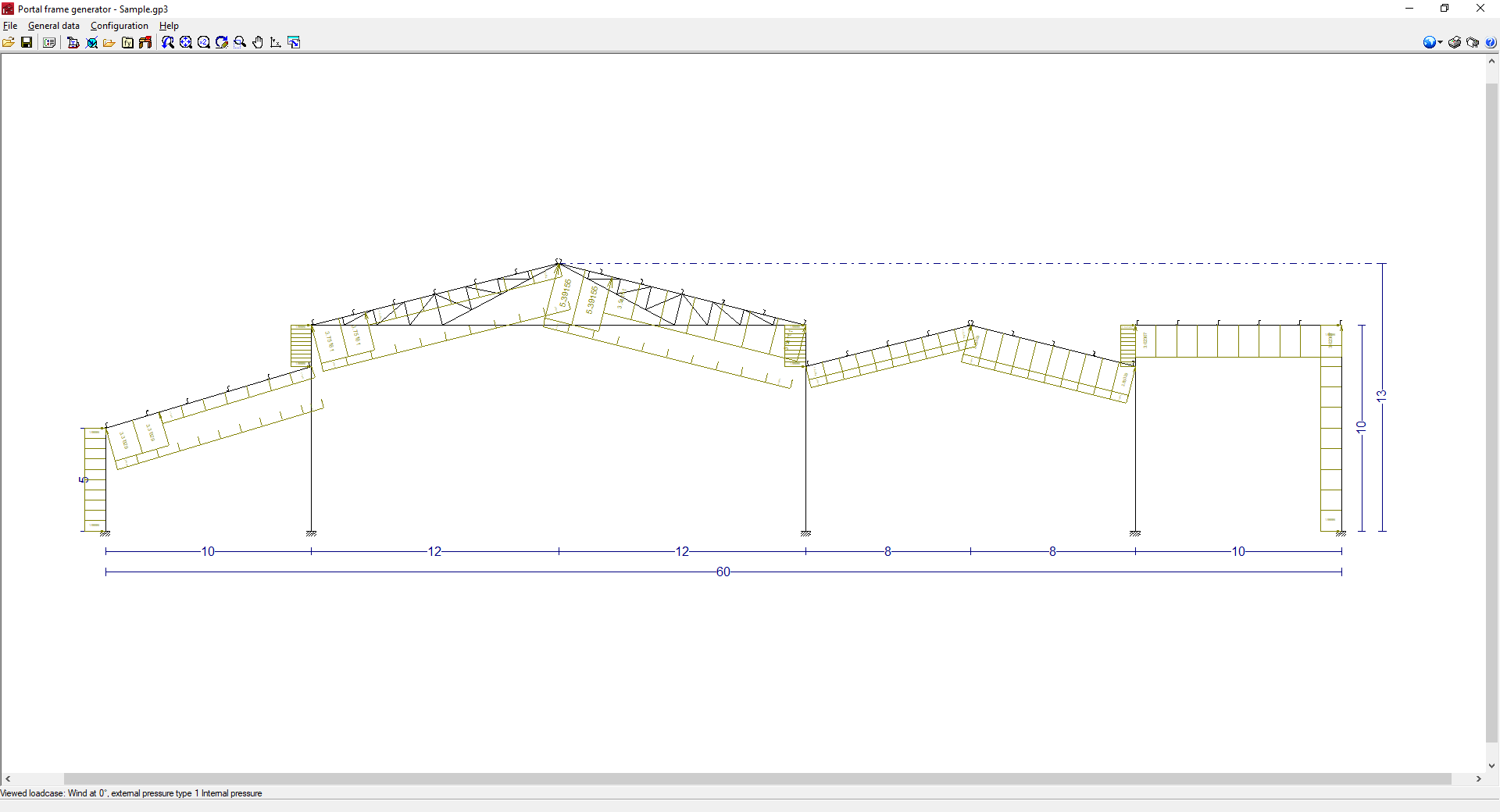
- Finally, in the central work area, which occupies most of the interface, the frames of the structure, as well as the lateral walls, can be entered, edited and displayed, and the dimensions, purlins and loads generated can be displayed.
Input and output sequence for generating portal frame structures
The generation of a portal frame structure can be carried out in the program by means of the following input and output sequence:
- Creating a new job (from "File", "New").
- Entering frames in the work area and configuration of their type and geometry (by clicking anywhere in the work area and selecting "New frame").
- (Optional) Entering lateral walls in the work area (by clicking on the lateral part of the work area and selecting "Lateral wall").
- Setting the material standards to be used in the analysis (from "Configuration", "Standards").
- Setting the general data of the job (from "General data", "General data of the job"), including the definition of the number of frames and their spacing, the existence of side and/or roof enclosures, and the configuration of their own weight, the overload of use on the roof and the wind and snow overloads.
- (Optional) Importing predefined section series or manufacturer's catalogues (from "General data", "Profile library management").
- (Optional) If necessary, creating user steels (from "General data", "User steel library").
- (Optional) Editing and analysing purlins on roofs and sides (from "General data", "Edit lateral and roof purlins", "Purlins on roofs/Purlins on sides").
- Printing reports and drawings of the job (from "File", "Job reports/Job drawings").
- Exporting to CYPE 3D (from "General data", "Export to CYPE 3D").
Frame examples
An example of a frame structure that can be developed in the program is shown below, indicating the layout of the elements and the options that can be used to enter them:
Multiple frame structure

- Dual pitch frame with straight Fink truss (by clicking anywhere in the work area and selecting "New frame", "Dual pitch", with roof type "Straight Fink truss").
- Dual pitch rigid frame (from "New frame", "Dual pitch", with roof type "Rigid frame").
- Mono pitch rigid frame (from "New frame", "Mono pitch", with roof type "Rigid frame"; frames can be reordered from "Move frame").
- Roof purlins (from "General data", select "Edit lateral and roof purlins" and then "Roof purlins").
- Sidewall (by clicking on the side of the work area and selecting "Lateral wall").
- Purlins on side walls (from "General data" select "Edit lateral and roof purlins" and then "Purlins on sides").
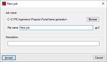
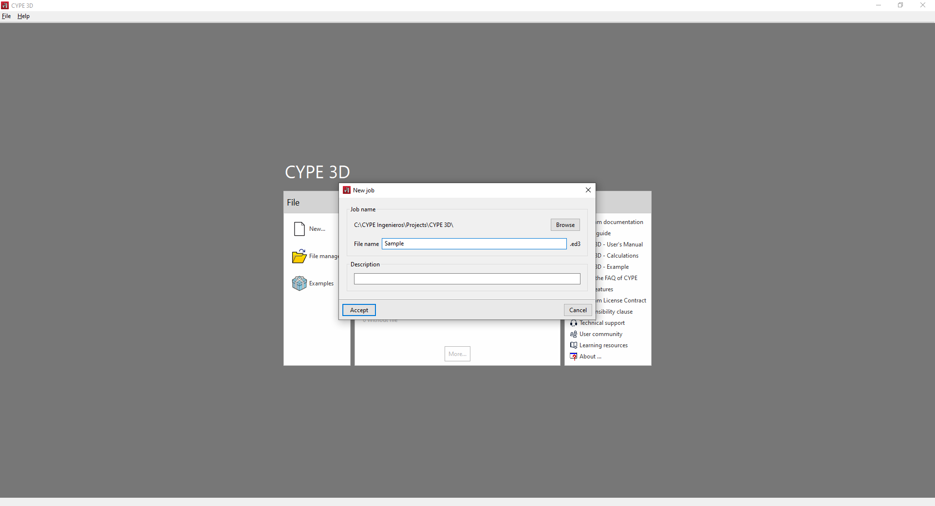
Creating a new job
When starting the app and clicking on "New", the possibility of creating a "New job" is offered. In the window for creating a new job, the path where the file will be stored can be consulted or modified, and, in addition, the "File name" and its "Description" must be entered.
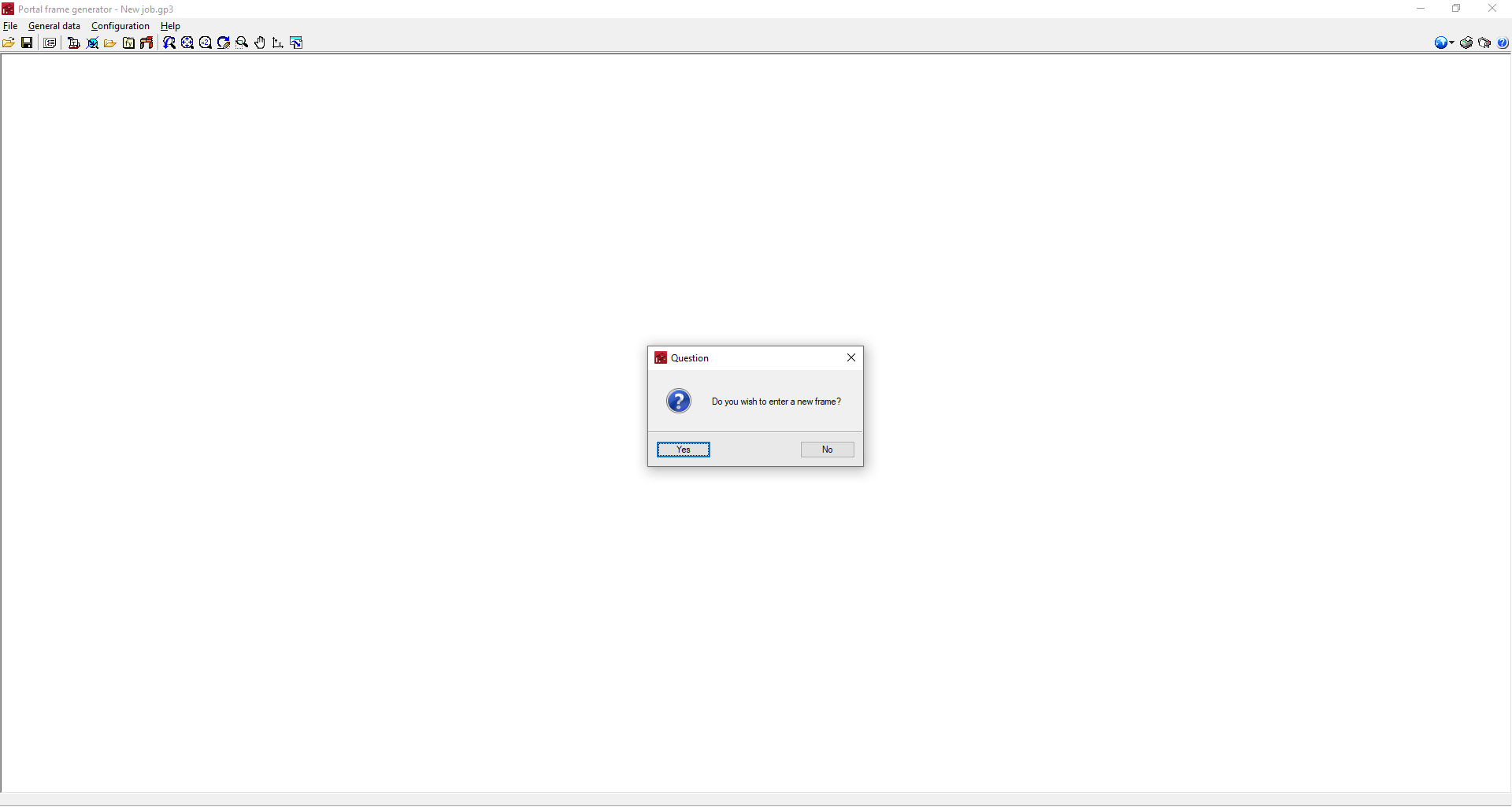
The program then asks in a dialogue box whether the first portal of the job is to be entered directly:
- If the answer is yes, the window for creating new frames will be opened. After entering them, the general interface will be displayed to continue the work.
- If the answer is no, the empty general interface will open. In this case, the first portal can be entered by clicking anywhere in the work area and selecting "New frame".
Entering and editing frames
Accessing the frame editing menu
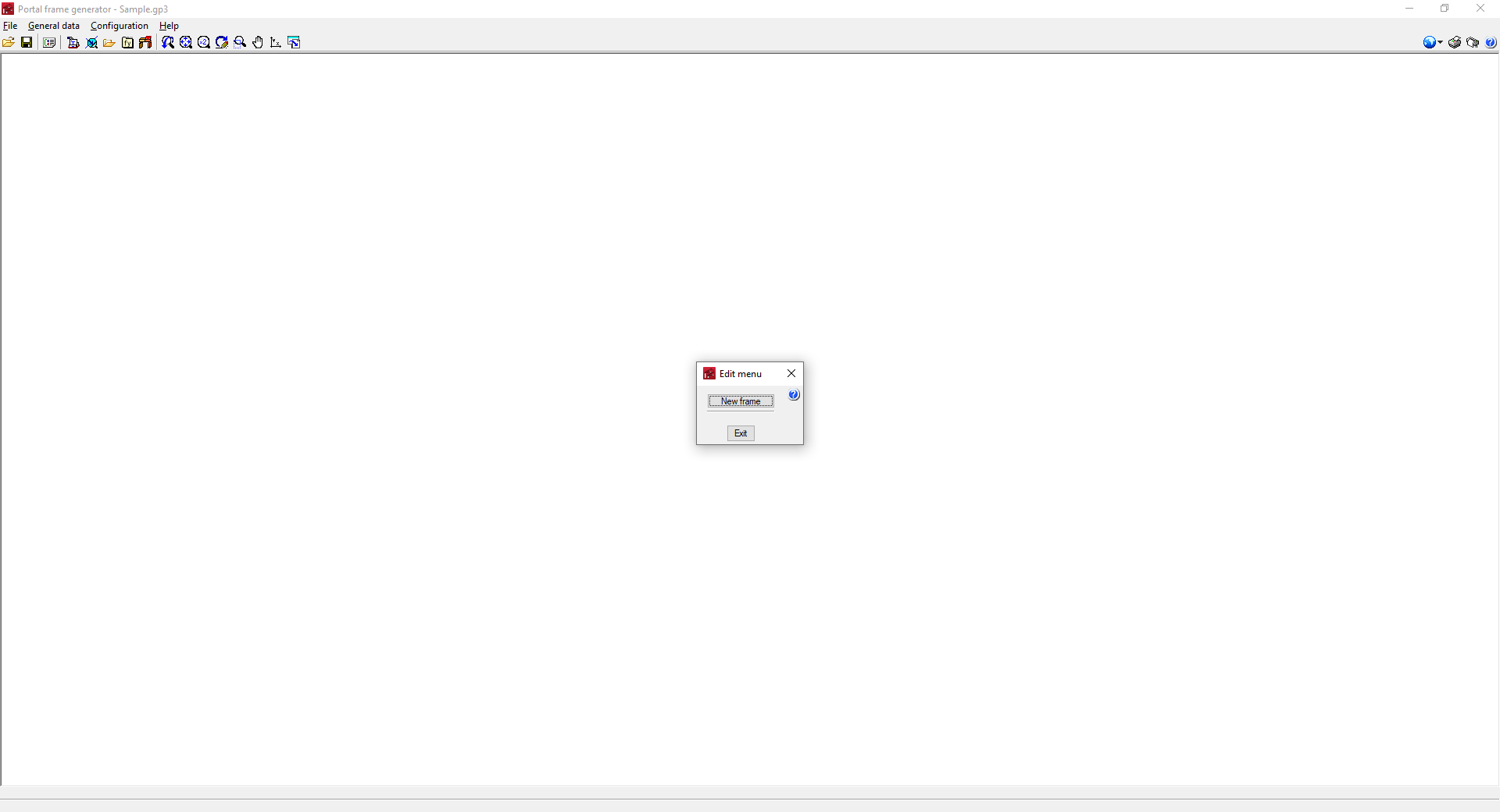
The "Editing menu" appears when clicking on the work area and includes the options that can be used to enter and define the geometry of the structure's frames. This menu varies depending on the area of the work area that is selected.
- When clicking on the empty work area before entering a frame, the "New frame" option will appear.
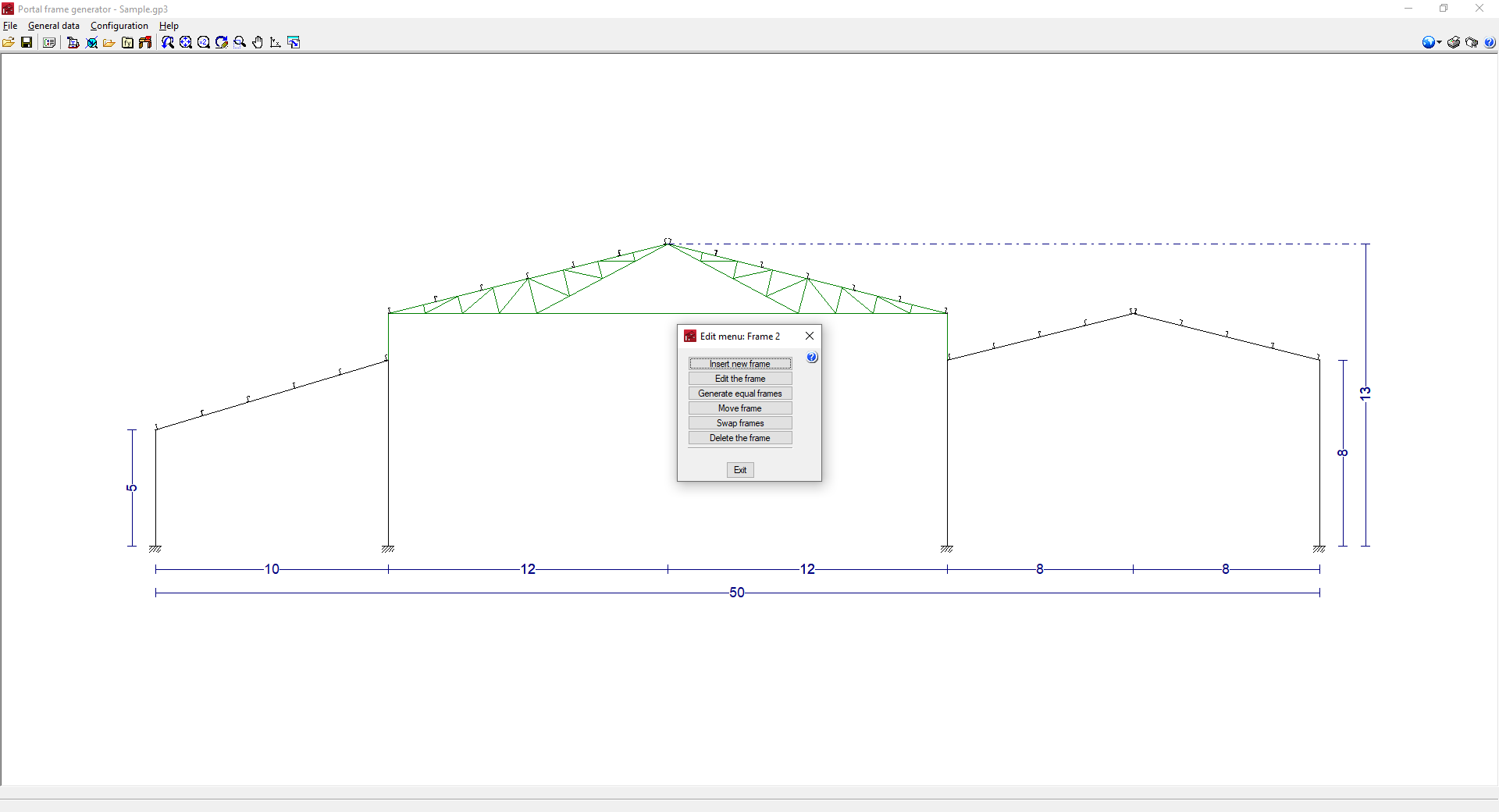
- When clicking on a previously entered frame, the following options will appear:
- Insert new frame
- Edit the frame
- Generate identical frames
- Move frame
- Swap frame
- Delete frame
- By clicking on the left or right side of the group of frames, the following options will appear:
- New frame
- Delete all frames
- Lateral wall
- By clicking on the top or bottom of the work area, the following options will appear:
- New frame
- Delete all frames
The use of the different options is detailed below.
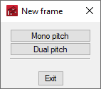
New frame/Insert new frame
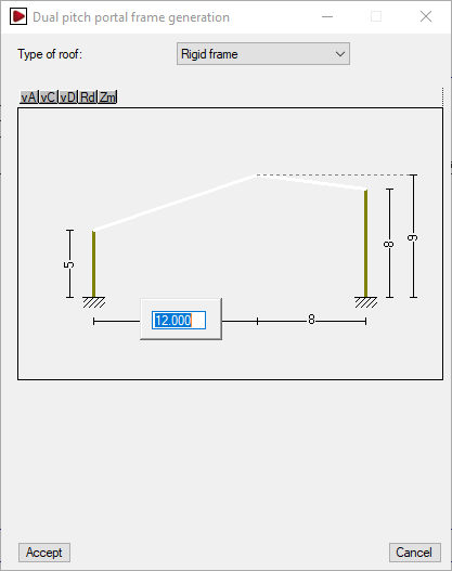
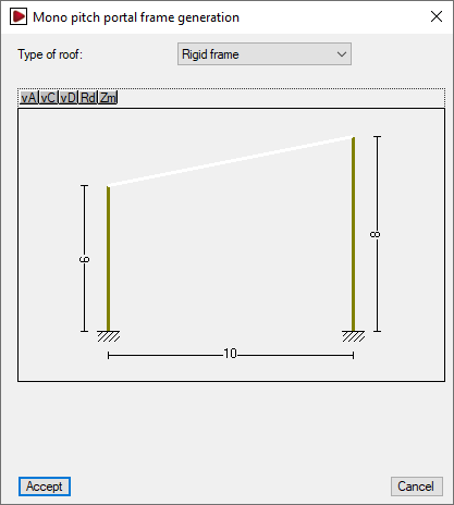
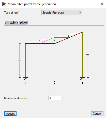
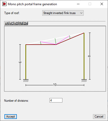
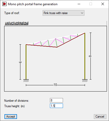
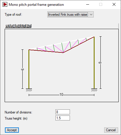
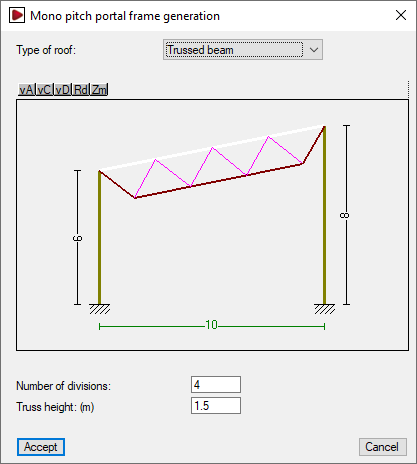
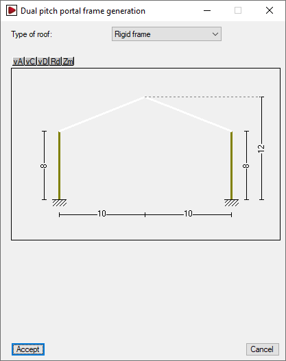
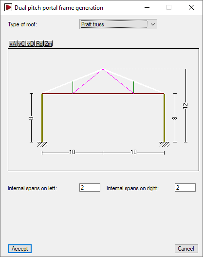
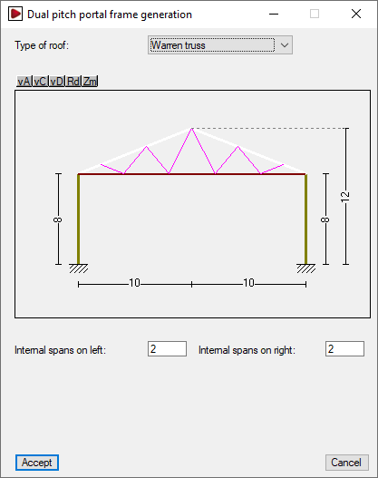
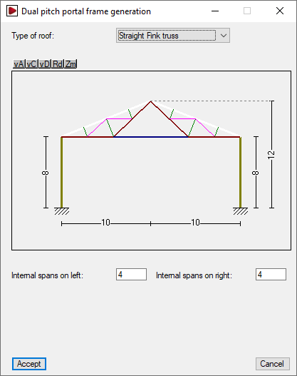
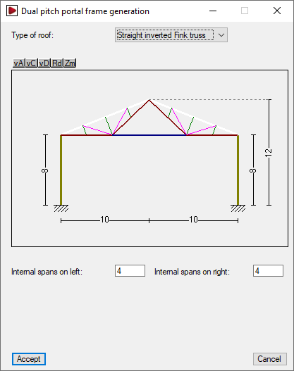
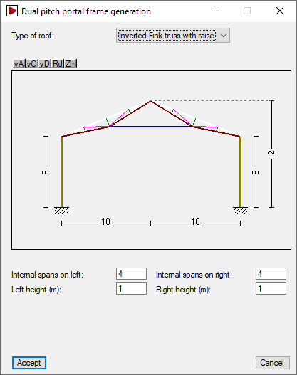
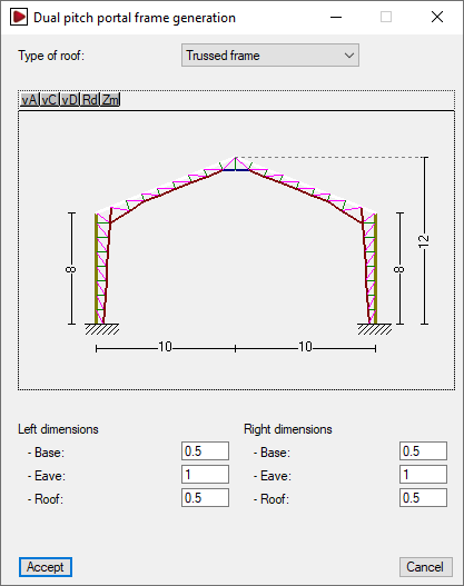
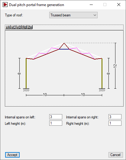
Creates a new frame by selecting "Mono pitch" or "Dual pitch" depending on the type of frame. Then, users can select the type of roof from the drop-down menu and edit the geometry of the frame by left-clicking directly on the dimensions shown in the editing window.
If one or more frame(s) have been previously inserted, the "Insert new frame" button creates the new frame to the right of the frame group.
Available roof types for mono pitch frames
The types available for mono pitch frames and the parameters required for their definition are as follows:
Roof types available for dual pitch frames
The types of dual pitch frame available and the parameters required for their definition are as follows:


Lateral wall
By clicking on the left or right side of the portal group, the "Lateral wall" option appears. This option is used to enter and define a perimeter wall to the structure on the selected side by activating the corresponding option.
Entering lateral walls can be used to adjust the generation of loads and buckling coefficients when exporting to CYPE 3D.
| Note: |
|---|
| To consider that the building has side cladding for generating wind loads and, therefore, is not an open canopy, the "With lateral wall cladding" option must be activated from "General data", "General data of the job". |
- With perimeter wall (optional)
Enters a perimeter wall on the selected side. The consideration of a perimeter wall allows the following parameters to be defined:- Wall height
Height of the perimeter wall. - Braces the column against buckling (optional)
Selecting this option means that the perimeter wall braces the columns against global buckling outside the portal frame drawing at the specified "Wall height", and against lateral buckling on both flanges. - Self-balanced (optional)
By selecting this option, the perimeter wall is assumed to be self-balancing, i.e. it supports by itself the wind load that is directly acting on it. Therefore, when exporting to CYPE 3D, the wind load below the specified "Wall height" is eliminated. If this option is kept deactivated, it is assumed that the wall transmits all the wind load received to the columns.
- Wall height

Frame editing options
The remaining frame editing options are as follows:
- Edit frame
Edits the selected frame by opening the editing window of the selected frame. - Generate equal frames
Copies the selected frame, which will be displayed in green, to the right of the last frame. The "Number of equal frames to generate" must be indicated in the dialogue box that appears below. - Move frame
This option only appears if more than one frame is generated. The selected frame, which will be displayed in green, can be moved to a new position. To do this, the program asks for the new position of the frame in the dialogue box that appears below. The numbering of the frame positions is from left to right. - Swap frames
This option only appears if more than one frame is generated. The selected frame, which will be displayed in green, can be swapped with another frame. To do this, the program asks for the new position of the frame in the dialogue box that appears below. The numbering of the frame positions is from left to right. - Delete frame
Deletes the selected frame. - Delete all frames
Deletes all frames.
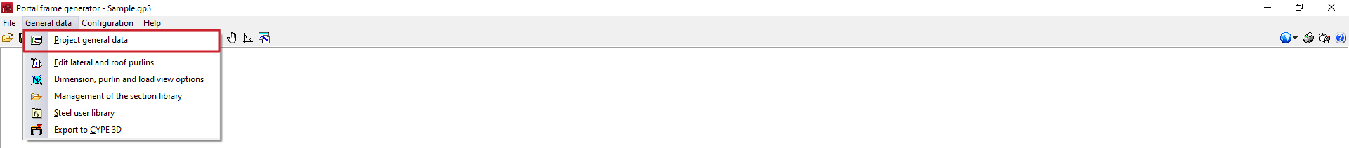
Configuration of the project general data
In the "General data" menu at the top, is the "Project general data". Clicking on this option opens a window where the geometry of the structure outside the drawing of the portal frame, the side and roof envelopes and their own weight, the overload of use on the roof and the wind and snow overloads are defined.
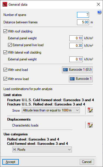
The options offered are as follows:
- Number of spans
Defines the number of spans between portal frames of the structure. - Distance between frames
Defines the distance between two consecutive frames of the structure. - With roof cladding (optional)
By activating this option, the structure is considered to have roof cladding, so that the wind and snow loads on the roof can be analysed. In addition, the self-weight and the live load on the roof envelope can be entered, if desired:- External panel weight
Value of the own weight of the roof cladding, minus the weight of the roof purlins, which can be entered with the later option "Edit lateral and roof purlins". - External panel live load (optional)
Value of the live load on the roof cladding.
- External panel weight
- With lateral wall cladding (optional)
When this option is activated, the structure is considered to have cladding on all sides, so the wind loads corresponding to a closed structure will be calculated. If kept deactivated, the structure will be considered as an open canopy.- External panel weight
Value of the own weight of the roof cladding, minus the weight of the lateral purlins, which can be entered with the later option "Edit lateral and roof purlins".
- External panel weight
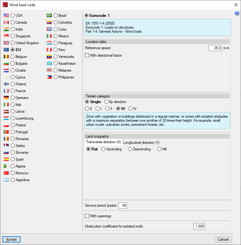
- With wind load (optional)
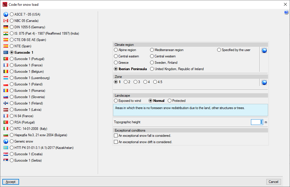
This section appears when activating the "With roof cladding" or "With lateral wall cladding" options. When this option is activated, clicking on the button available on the right opens a window where the wind load analysis standard must be selected from those available, as well as adjusting the related parameters. - With snow load (optional)
This section appears when the "With roof cladding" option is activated. When this option is activated, clicking on the button available on the right opens a window where the snow overload analysis standard must be selected from those available, as well as adjusting the related parameters. - Load combinations for purlin analysis
This section appears when activating the "With roof cladding" or "With lateral wall cladding" options. This checks the criteria for generating load combinations for analysing purlins and, if necessary, selects one of the cases available in the drop-down menu, depending on the material standard defined in the "Configuration" menu. - Use categories
This section only appears if the "External panel live load" option has been activated. This is used to select the category of use to be applied to this live load from those available, depending on the material standard defined in the "Configuration" menu.
Editing lateral and roof purlins
In the "General data" menu at the top, there is an "Edit lateral and roof purlins" option, which can be used to define, check and design steel purlins on the roof and/or on the sides of the structure.
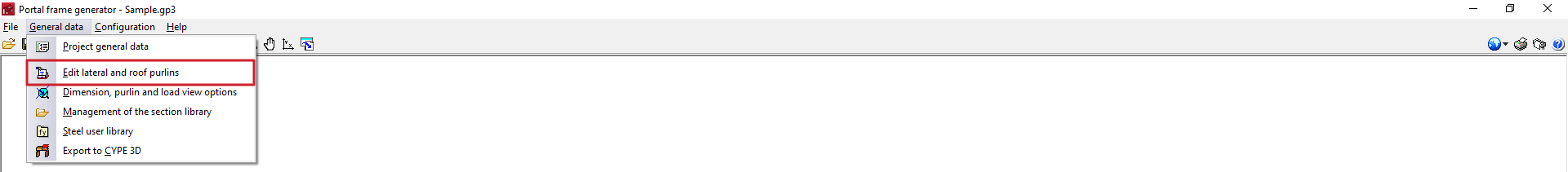
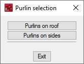
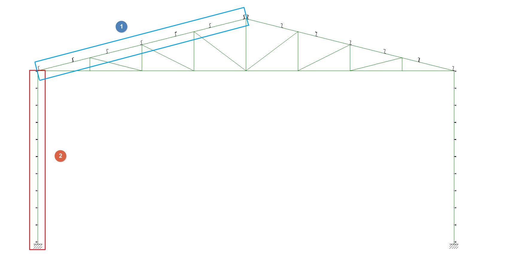
Purlins can be inserted in the roof sides of all inserted portal frames (1) with the "Purlins on roof" option, and purlins on both façade sides (2) with the "Purlins on sides" option.
Selecting one of these options opens the "Edit roof purlins" or "Edit lateral purlins" panel.
Editing purlins
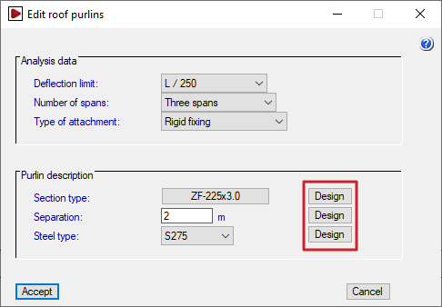
The options offered in each purlin editing panel are as follows:
- Analysis data
- Deflection limit
Sets the maximum deflection allowed for the purlins according to the light they cover. By default, a deflection limit of L/250 is taken. It is also possible to indicate "Unlimited" to set no deflection limit. - Number of spans (One span / Two spans / Three spans)
Number of spans spanned by the purlins in continuity and considered in the design model. The program checks the purlin in all possible positions and retains the most unfavourable results.
This parameter does not refer to the number of spans in the structure, which is defined in "General project data". However, users must take into account that if the different purlin sections are linked by overlapping between the portal frames, there is a continuity in the transmission of forces, so that the purlin should be analysed with the same number of spans as the complete structure. - Type of attachment (Non-collaborating roof / Hook fixing / Rigid fixing)
This is used to indicate the type of fastening of the roof cladding or side facades to the purlins. This defines the loads with which the purlins must be checked. The choice of fastening case must ensure that the construction reality corresponds to the selected design model.- Non-collaborating roof
The roof or façade does not collaborate with the purlins in their support, so they must be analysed with the full load, inside and outside the roof or façade drawing and including torsion. - Hook fixing
The roof or façade is assumed to be infinitely rigid in its drawing. The purlins support bending and shear only in the drawing perpendicular to the roof or façade, plus torsion (warping is neglected). - Rigid fixing
The roof or façade is assumed to be infinitely rigid in its drawing and also prevents the purlins from twisting. The purlins only support the bending and shear in the drawing perpendicular to the roof or façade, and there is no torsional moment. The deflected bending is also not considered for sections that are not on major axes.
- Non-collaborating roof
- Deflection limit
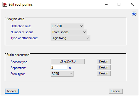
- Purlin description
- Section type
Selects the purlin section by accessing the "Section selection" window. - Separation
Enters the value of separation between the purlins. - Steel type
Used to select the type of steel from those available according to the standard chosen in "Configuration". The steels created from the "User steel library", under "General data", are also available for selection here.
- Section type
| Checks carried out on the purlins depending on the type of fixing | Non-collaborating roof | Hook fixing | Rigid fixing |
| Bending and shear in the drawing of the roof or façade | Yes | No | No |
| Bending and shear in the drawing perpendicular to the roof or façade | Yes | Yes | Yes |
| Torsional moment | Yes | Yes | No |
| Lateral buckling of the outer wing | Yes | No | No |
| Lateral buckling of the inner wing | Yes | Yes | No |
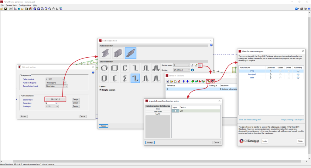
Section selection options
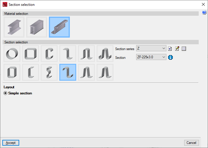
Click on the button available in the "Section type" to access the "Section selection" window.
In the upper part of this window, the material of the purlins is selected, whether they are rolled steel profiles, reinforced rolled steel profiles or formed steel sections. Below, the type of section is selected from among those available, and its layout is defined in the lower part.
The drop-down "Section series" and "Section" menus can be used to select the desired series and, within this series, the section of the series to be used in the definition of the purlins.
The management of the available section series is carried out by means of the options located next to the drop-down menus. From here, predefined section series can be imported, manufacturer catalogues can be imported, or section series can be created and defined manually, as well as importing and exporting the information to files on disk. The program will also display the predefined section series or manufacturer catalogues imported via the "Section library management" option in the "General data" menu.
Finally, next to the "Section" drop-down menu, the "Properties of the selected section" can be consulted.
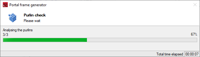
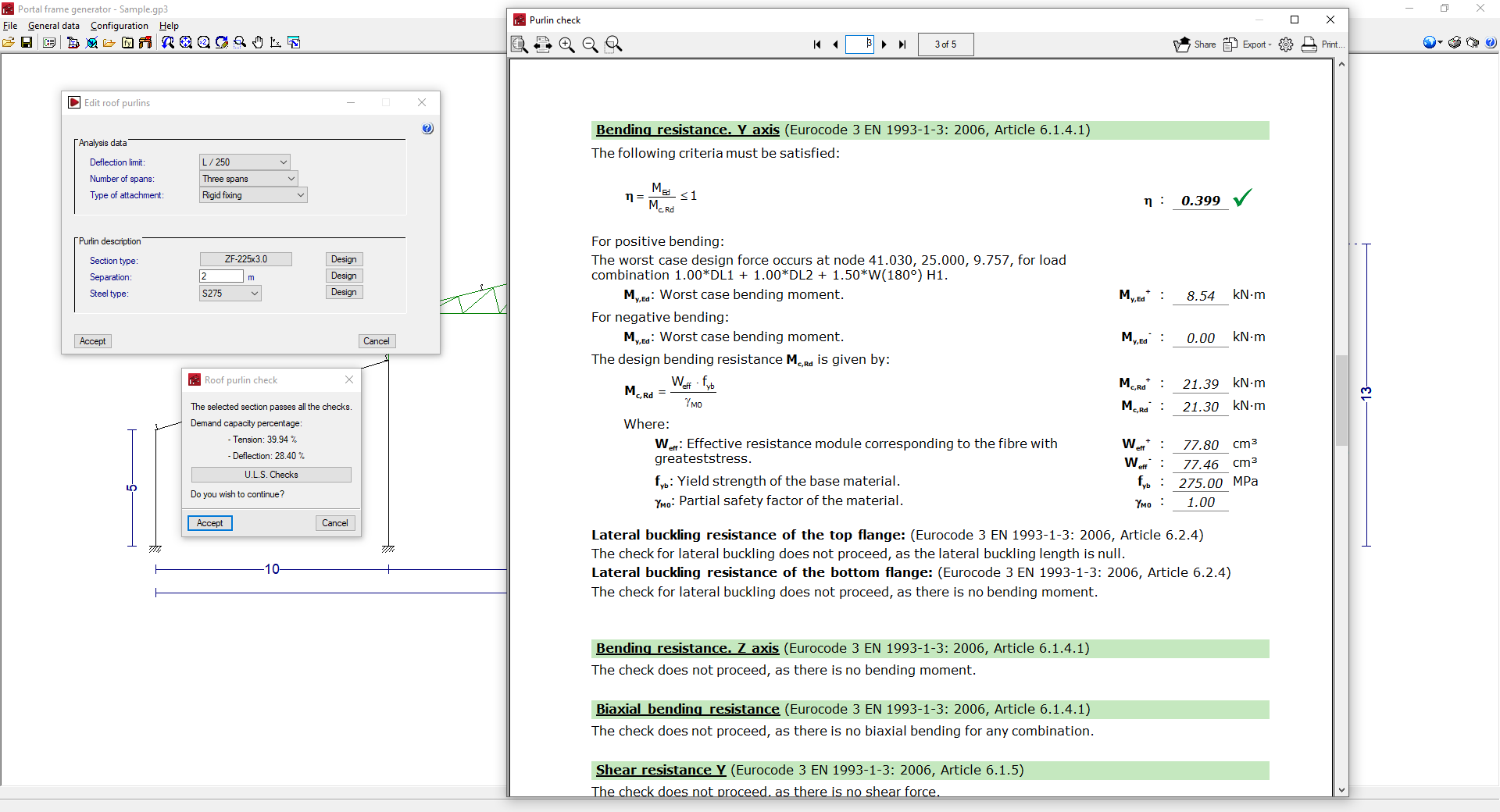
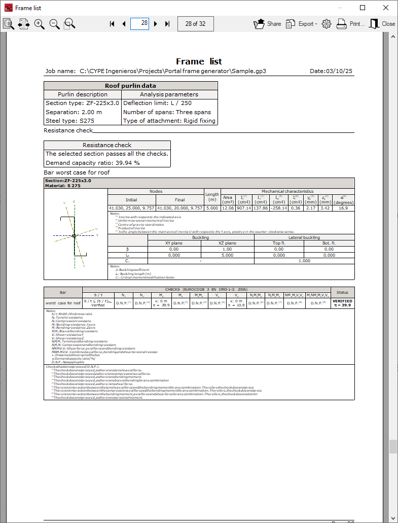
Purlin check
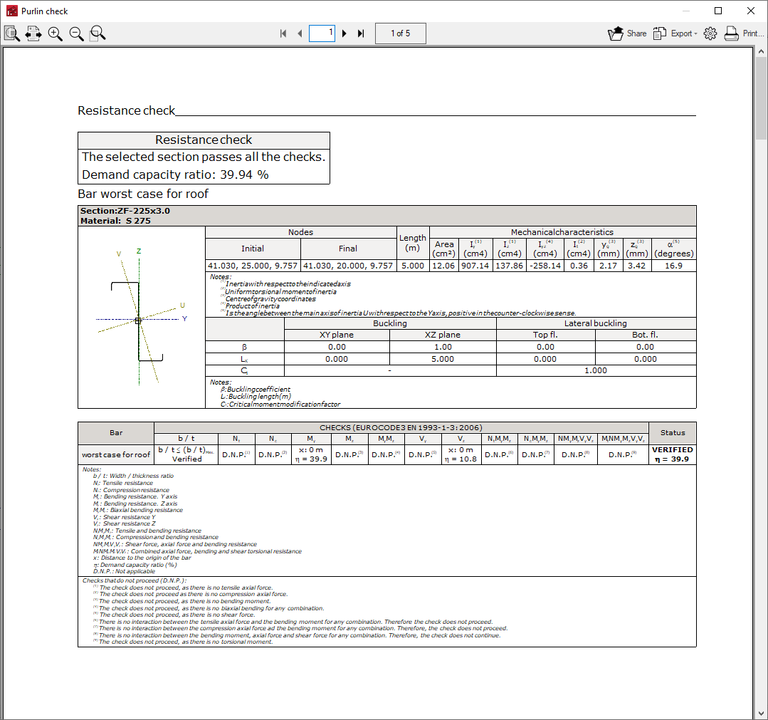
When accepting the purlin editing panel, the program will check the sections according to the data and analysis conditions that have been defined.
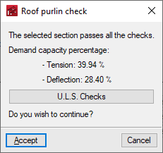
At the end of this analysis process, a dialogue box is displayed with the percentages of utilisation at tension and at deflection.
It is also possible to obtain a report with the checks carried out by clicking on the "U.L.S checks" option. The program can print this report directly or generate HTML, PDF, TXT, RTF or DOCX files.
Purlin design
The three "Design" buttons on the right side of the purlin editing panel can be used to optimise the selected section and the separation between purlins:
- The design carried out with the first button (next to "Section type") keeps the selected purlin separation and steel type, and tries to find the section of the series that complies with all the checks.
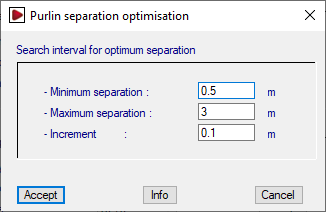
- The design carried out with the second button (next to "Separation") keeps the selected section and steel type, and tries to find the optimal purlin separation that complies with all checks. The optimum separation is found by starting with the "Maximum separation" and reducing it by the value of "Increment" until the "Minimum separation" is reached.
- Finally, the design performed with the third button (next to "Steel type") keeps only the selected steel type, and tries to find together the section and the optimal purlin separation that fulfils all the checks. For each section, the optimum separation is searched for by starting with the "Maximum separation" and reducing it by the value of "Increment" until the "Minimum separation" is reached.
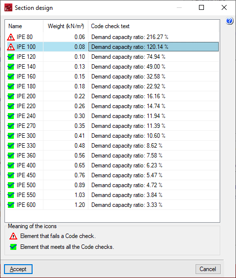
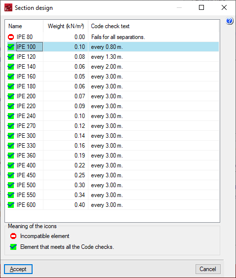
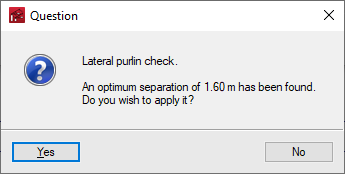
At the end of the design process, the program displays the following:
- In the case of section design, a report is displayed with the compliance status for each of the sections of the series for the selected separation, indicating its name, weight and the demand capacity ratio percentage.
- In the case of a separation design, a dialogue box opens with the optimum separation found for the selected section, which can be applied or not by accepting the panel.
- In the case of a joint section and separation design, a report is displayed with the required gap for each section of the series, as well as its compliance status, name and weight.
In the displayed section lists, the desired section can be selected by double-clicking on it with the left mouse button. Subsequently, the window must be accepted to apply the changes.
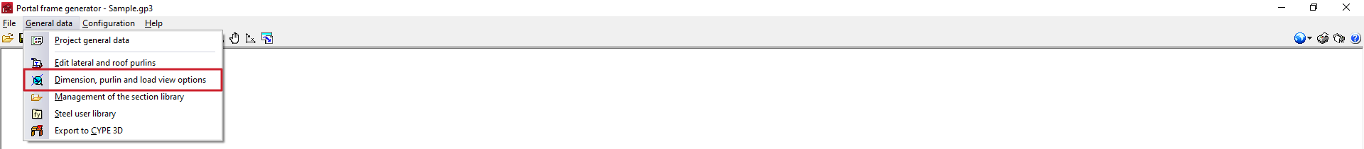
Viewing options for dimensions, purlins and loads
The "General data" menu at the top of the screen contains the "View options for dimensions, purlins and loads", which allow users to adjust the information displayed on the screen:
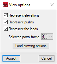
The "View options" window offers the following options:
- Represent elevations (optional)
Displays the dimensions of the portal frames entered on the screen. - Represent purlins (optional)
Displays the section and layout of the roof purlins and side façades on the screen. - Represent the loads (optional)
Displays the loads generated by the program according to the data entered. When this option is activated, the following options are enabled:- Selected frame
This drop-down menu is used to select the specific portal frame for which the loads are to be represented. - Load drawing options
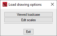
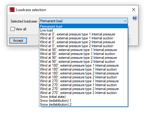
These options adjust the display of the loads on the screen.- Viewed loadcase
Selects the loadcase to be displayed on the screen. If the "View all" option is checked, the loads for all loadcases shall be displayed.- Selected load
- See all (optional)
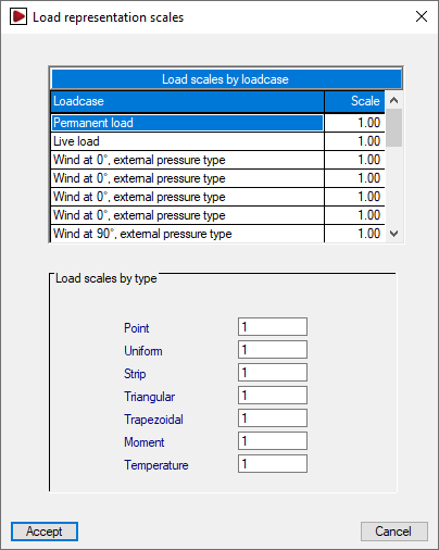
- Edit scales
Modifies the display scale of the loads by loadcase or by type.- Load scales by loadcase
- Load scales by type
- Viewed loadcase
- Selected frame
By accepting the "View options" window, the selected dimensions, purlins and/or loads will be displayed on the screen according to the specified settings.
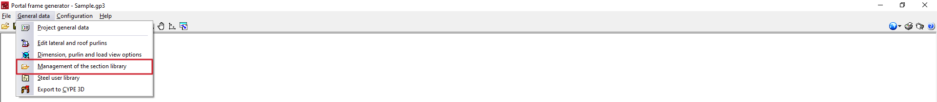
Managing the section library
In the "General data" menu at the top, there is the "Management of the section library" option, which can import of predefined section series and manufacturer catalogues, as well as the export of the series to files on disk:
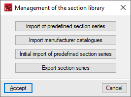
The "Management of the section library" window offers the following options:
- Import of predefined section series
- Import manufacturer catalogues
- Initial import of predefined section series
- Export section series
These options are described in detail below:
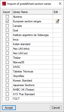
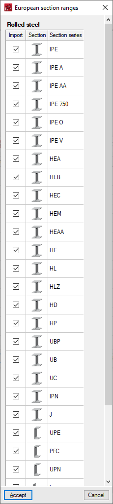
Importing pre-defined section series
This option is used to select the predefined section series to be imported from the available ones based on different reports and regulations. To do so, activate the "Import" checkbox and accept.
The "Edit" button, on the right-hand side of each of the selected libraries, allows users to detail the specific series of each library that they wish to import.
Initial import of predefined section series
The "Initial import of predefined section series" option indicates the section series that will be automatically imported when a new job is created in the program.
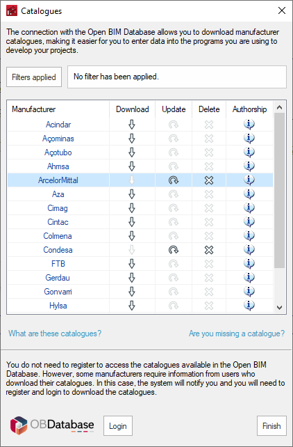
Importing manufacturer catalogues
Downloads profile series from manufacturers' catalogues using the connection to the Open BIM Database.
Clicking on this option opens a window with the available manufacturer catalogues.
Using the "Applied filters" option, filters can be applied by "Category" to show only manufacturers that offer product catalogues with these characteristics.
Download catalogues
The following options are shown for each manufacturer:
- Download
Selects and downloads manufacturer's catalogues. - Upload
Updates the selected manufacturer's catalogues to the latest version, overwriting the downloaded version. - Delete
Deletes the selected manufacturer's catalogue.
Connection to Open BIM Database
At the bottom of this dialogue box, the program allows users to log in with an Open BIM Database account and password.
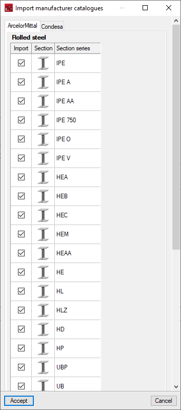
When accepting, the program displays a window where the section series import from each manufacturer's selected catalogues is confirmed by activating or deactivating the corresponding checkboxes.
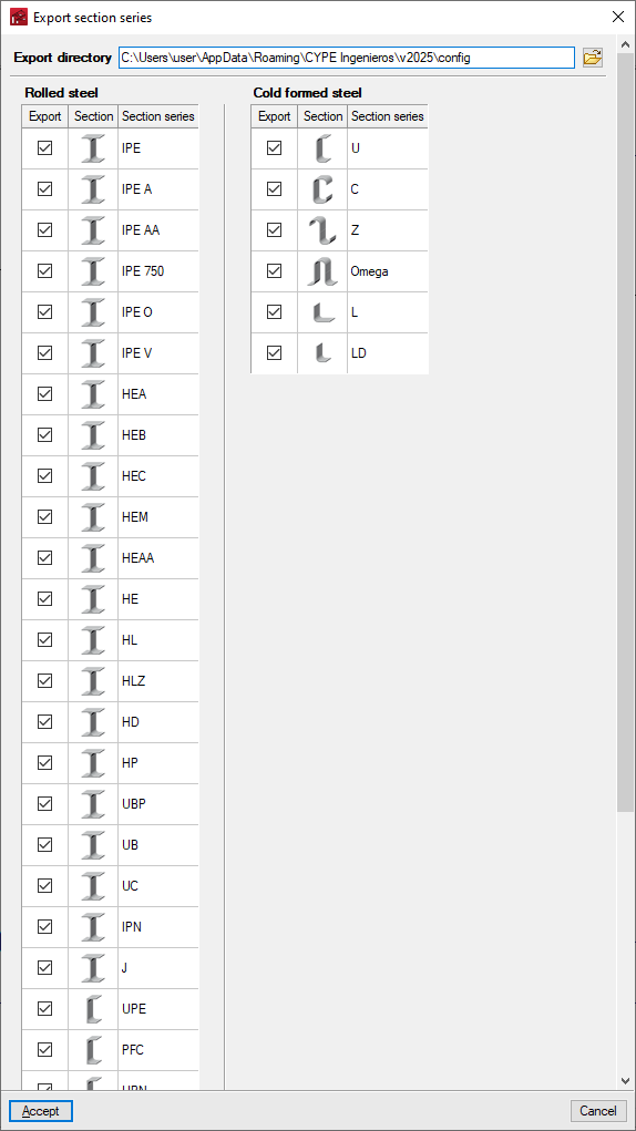
Export section series
The section series imported or created on the job can be exported to files on disk using this option. The program displays the location of the exported files and also allows users to select the series to be exported.
Use of imported section series
The predefined section series and imported section series from manufacturer's catalogues will be available in the corresponding drop-down list when selecting the section type using the "Editing roof and lateral purlins" option, which can be found under "General data".
Additionally, by accessing the "Edit the list of elements" option, it is possible to consult or modify these series, as well as import predefined section series and import specific manufacturer catalogues for the type of section selected by clicking on the corresponding options at the top of the list. From here, it is also possible to import files on disk containing section series information of the selected type.
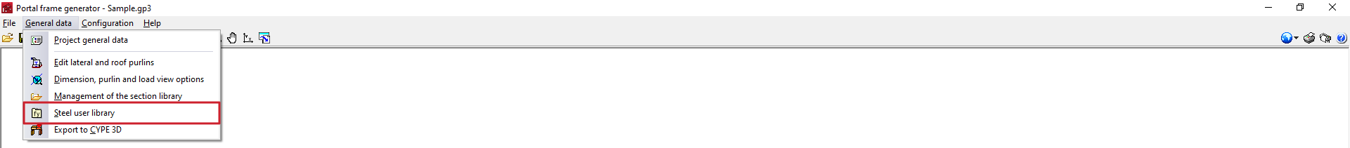
Steel user library
In the "General data" menu at the top, there is a "Steel user library" option, which allows users to create and edit user rolled and formed steel types by manually entering their characteristics.
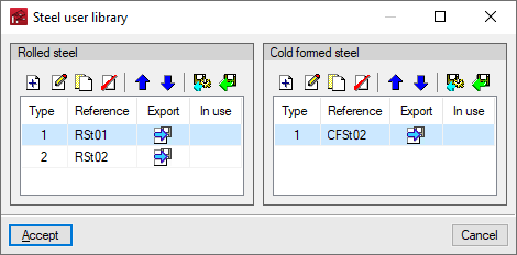
The "Steel user library" window displays two lists, "Rolled steel" and "Cold formed steel".
In each of them, it is possible to create, edit, copy, delete or reorder user steel types, as well as import or export them to files on disk.
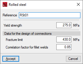
When creating a user steel, it is necessary to indicate its characteristics, such as "Reference" or "Elastic limit".
The user steels created will be available in the drop-down menu "Steel type" when selecting the section type, after using the "Editing roof and lateral purlins" option under "General data".
Results output
In addition to exporting to CYPE 3D, the program offers the following results from the Portal frame generator interface itself:
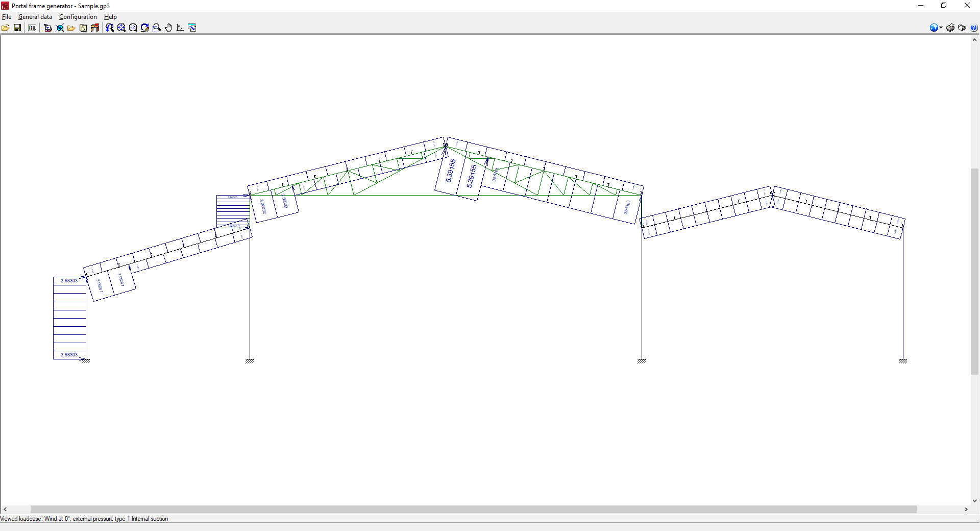
Checking generated loads on screen
The program can be used to consult on screen the layout and value of the loads generated, drawn directly on the portal frame group. To do this, use the "Options for displaying dimensions, purlins and loads" option under "General data" and select the loads in view and the portal frame whose loads are to be represented. The scale at which the loads are displayed can also be adjusted.
Checking purlin analysis results
In the process of selecting and editing the roof and side façade purlins (from "Editing roof and lateral purlins", in "General data"), the program can consult the results of the analysis according to the data entered, as well as generate a specific checklist.
The purlin check report can be printed directly or exported to HTML, PDF, TXT, RTF or DOCX files.
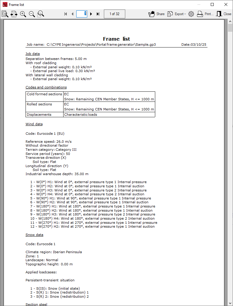
Reports
The program can print the complete reports of the job directly or generate HTML, PDF, TXT, RTF or DOCX files.
The reports are obtained via the "Job reports" option in the "File" menu or from the right-hand side of the toolbar at the top.
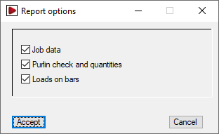
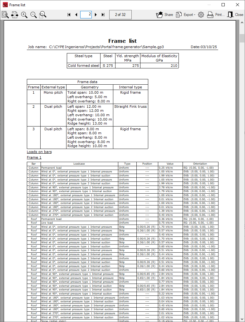
The job reports include the following sections, which can be activated or deactivated:
- Report options
- Job data (options)
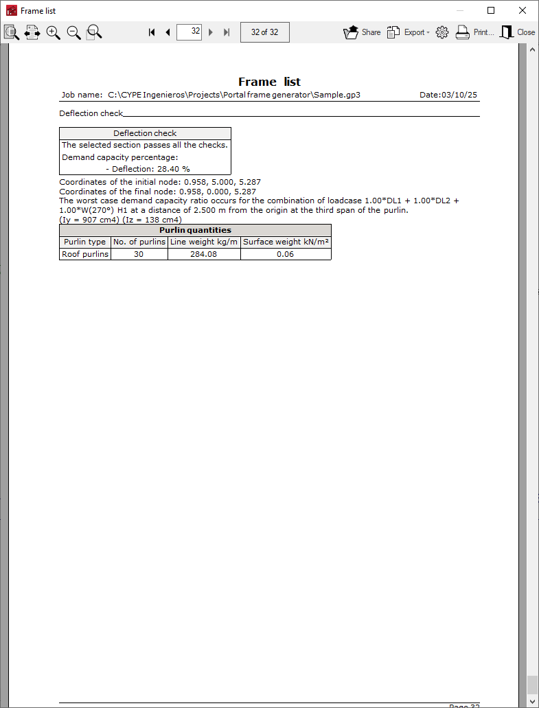
- Purlin check and quantities (options)
- Loads on bars (options)
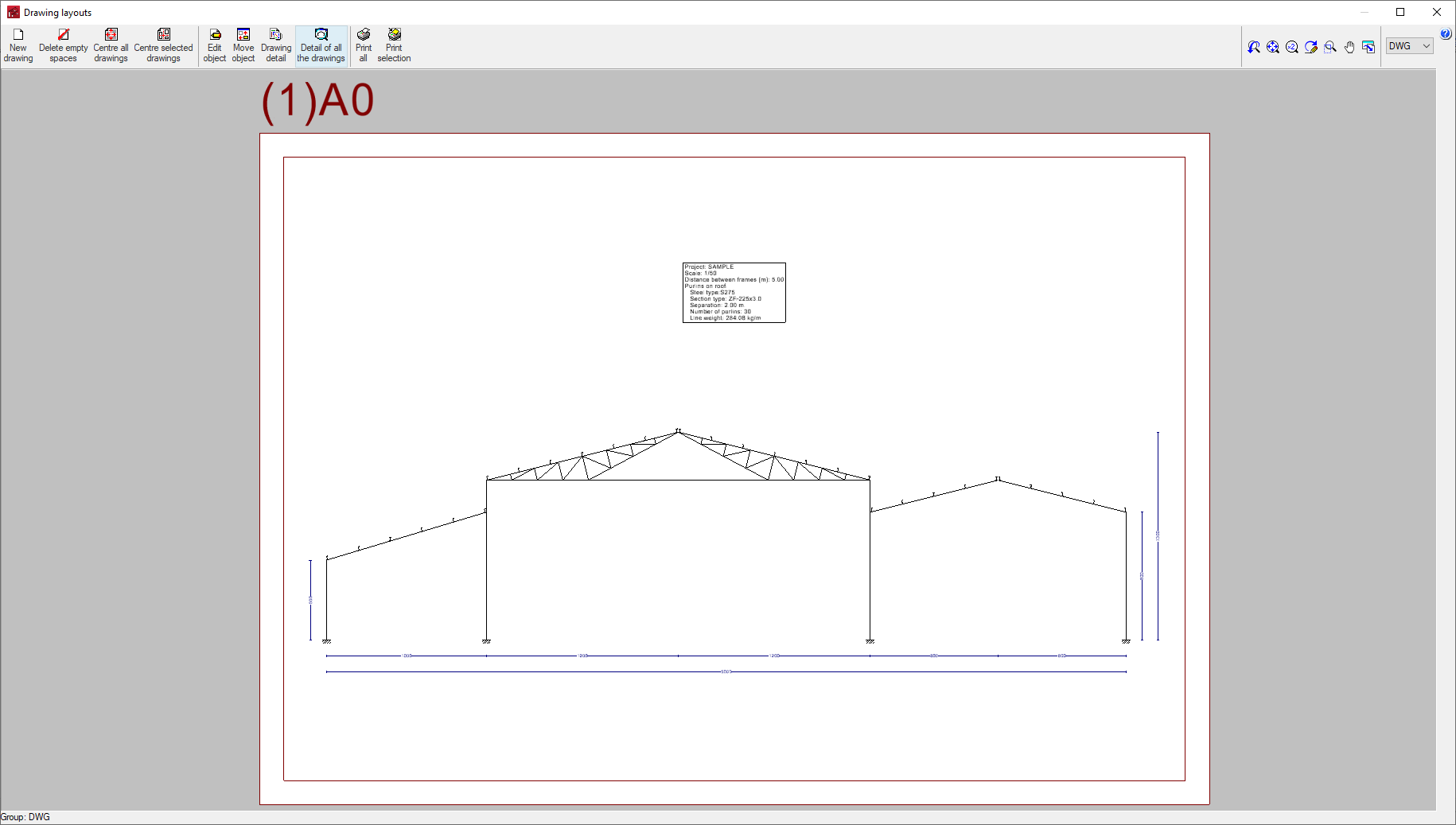
Drawings
The program can print the drawing of the defined portal group on any graphic peripheral device configured on the computer or create DWG, DXF or PDF files.
The drawings are obtained from the "Job drawings" option in the "File" menu or from the right-hand side of the toolbar at the top.
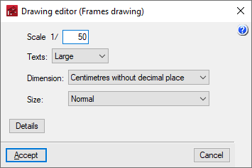
The editing of the drawing offers the following options:
- Scale
- Texts
- Dimension
- Size
- Details
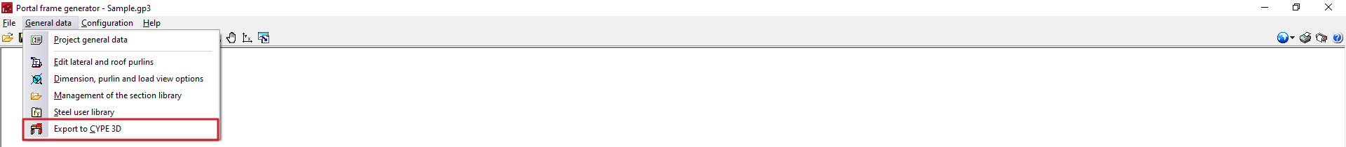
Exporting to CYPE 3D
In the “General data” menu at the top, there is the “Export to CYPE 3D” option, which allows users to configure the generation parameters of the portal frame structure exported from Portal frame generator to the CYPE 3D program.
When using this option, the program will first perform a check of the purlins with the defined data. Then, should the user wish to continue, it will open the "Options for exporting to CYPE 3D" window.
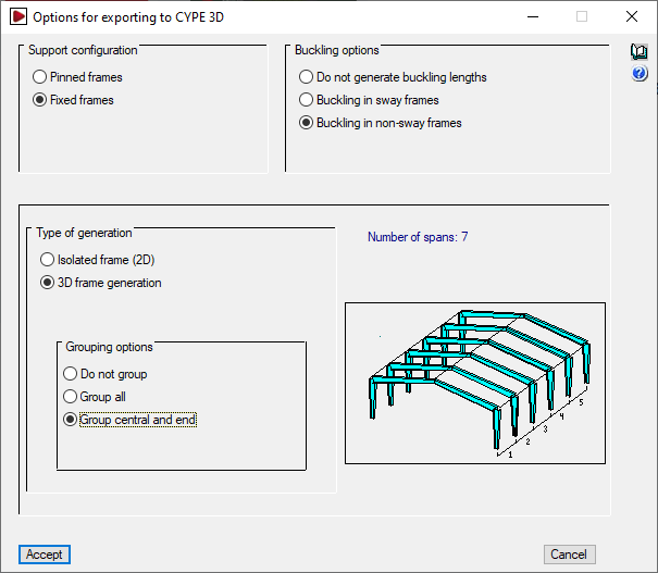
Options for exporting to CYPE 3D
In this window, the following aspects must be configured:
- Support configuration
Sets the type of external bracing to be generated at the foot of the columns of the portal frame in CYPE 3D. The selection of the support type will also influence the determination of the buckling lengths.- Pinned frames
An "Articulation" type external connection shall be generated at the foot of the columns. In the generation of buckling lengths, lintels with twice the inertia of the columns shall be assumed. - Fixed frames
An "Embedding" type external connection shall be generated at the foot of the columns. In the generation of buckling lengths, lintels with the same inertia as the columns shall be assumed, and an "Articulation" external connection shall be generated at the foot of the columns. In the generation of buckling lengths, lintels with twice the inertia of the columns shall be assumed.
- Pinned frames
- Buckling options
Sets the buckling lengths assigned to the bars generated in the export. The program shall generate the buckling lengths for all the bars of the portal frame in case of using the "Buckling in sway frames" or "Buckling in non-sway frames" options. The building shall be considered to be intraslational in the longitudinal direction. The difference between translational and intraslational portal frames affects the analysis of the buckling lengths in the drawing of the portal frame and only the supports.- Do not generate buckling lengths
If this option is selected, buckling coefficients equal to one shall be taken. - Buckling in sway frames
Horizontal displacement of the column heads in the drawing of the portal frame is not prevented. This is the most frequent case and the one selected by default. - Buckling in non-sway frames
Horizontal displacement of the column heads in the drawing of the portal frame is prevented by the presence of diagonals or other bracing.
- Do not generate buckling lengths
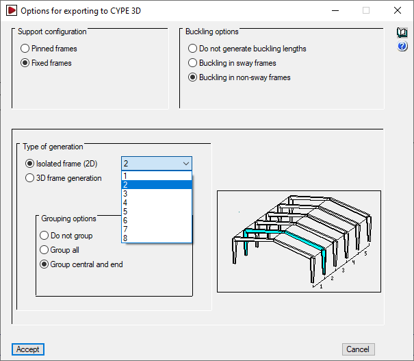
- Type of generation
- Isolated frame (2D)
A structure with a single isolated portal frame will be generated. The portal frame of the structure to be exported must be selected. - 3D frame generation
The complete structure with all frames, including the gables, is generated and exported.
- Isolated frame (2D)
- Grouping options
With this option, frames can be grouped in CYPE 3D, so that when the elements of a frame are modified, the elements of all the frames grouped with it are modified. The following grouping options are available:- Do not group drawings
Each frame in CYPE 3D is independent of the others. - Group all
All frames shall be grouped into a single group, including the gables or end frames which, in this case, shall have the same load as the central frames. - Grouping central and end
Two sets of frames are formed, one with the gables (the frames at the two ends of the structure), and one with all the frames in between. This is the default option.
- Do not group drawings
Creating a job in CYPE 3D
By accepting the "Options for exporting to CYPE 3D" window, the program will save the data of the Portal frame generator job, close this program and then automatically open the CYPE 3D application if it is installed.
A new job will be generated in CYPE 3D. The configuration of the general data must be checked, as well as the "Name" and "Description" of the job, together with the saving path of the CYPE 3D file.
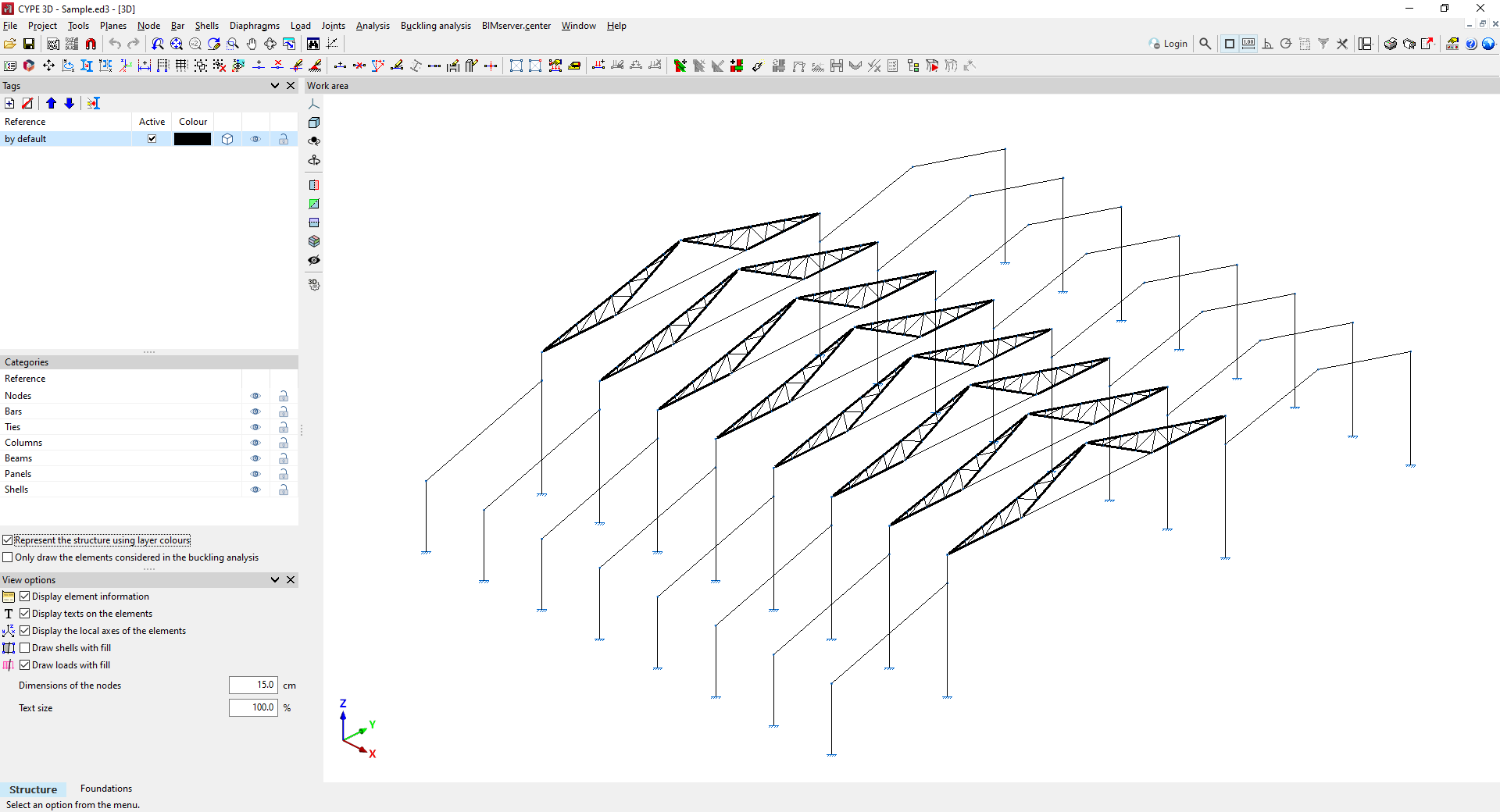
Information generated in CYPE 3D
Finally, the program will open the CYPE 3D interface, where the portal frame structure generated in the new job can be viewed (which must be saved if it is to be retained), and work can continue with the CYPE 3D options for analysing the structure.
The information generated includes the following, together with the CYPE 3D options that allow it to be modified or revised:
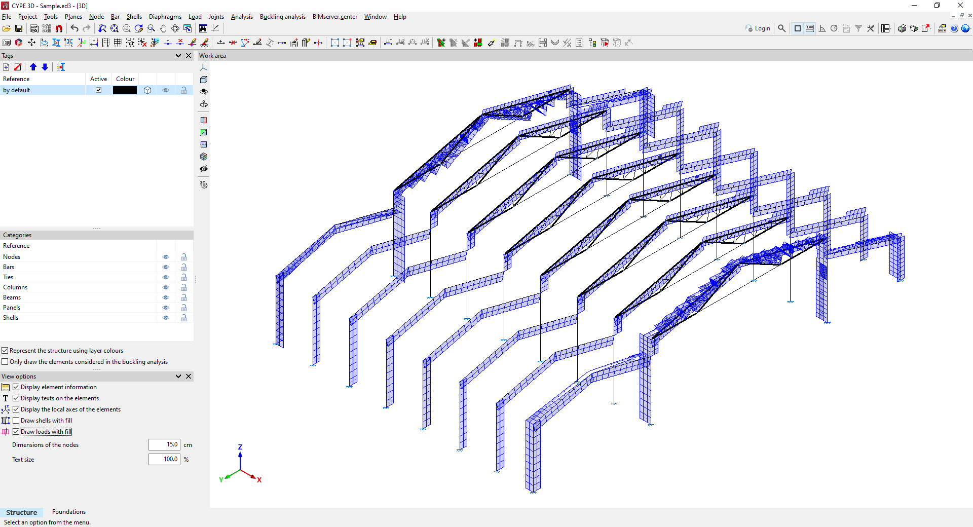
- The bar geometry of the indicated portal frame or of the complete system of frames, which can be modified or completed with the options of the "Bar" menu. The type and cross-section of the portal frame sections must be defined from "Bar" by clicking on "Describe section", and new bars must be entered if necessary, such as the tie beams between frames. The geometry of the purlins is not exported, but their self-weight is.
- The necessary loadcases can be checked from "Job" by accessing "General data" and selecting "Additional loadcases".
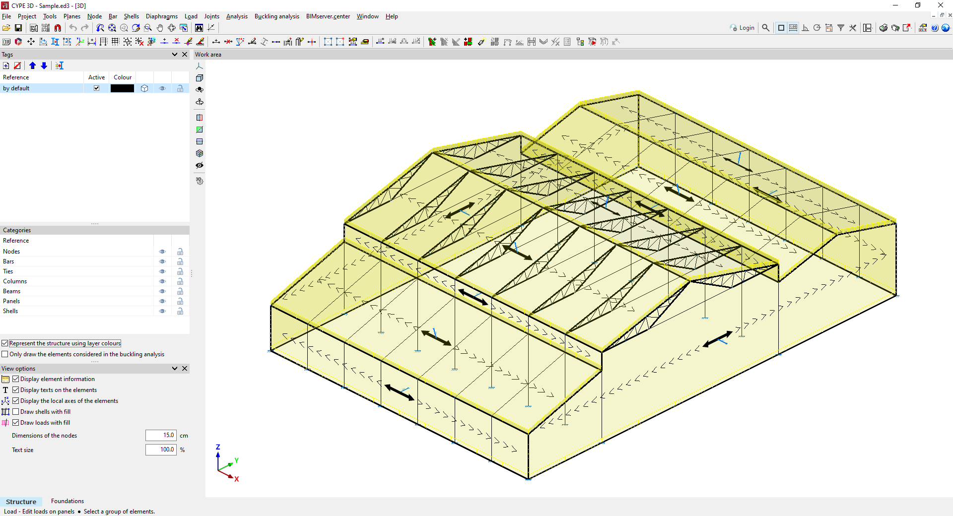
- If applicable, the necessary load panels that carry out the distribution of surface loads and that incorporate the information of the self-weight of the envelopes and purlins, and/or of the live load on the roof. They can be reviewed from the options related to the load sheets in the "Load" menu.
- Wind and snow surface loads can be reviewed from the options related to them in the "Load" menu.
- The grouping of frames, which can be reviewed under "Bar" in "Group/Ungroup";
- The buckling lengths or buckling coefficients of the frame members, which can be reviewed under "Bar" by selecting "Buckling".
- The supports or external connections of the columns, which can be checked from "Node" by selecting "External connection".The information generated includes the following, together with the CYPE 3D options that allow it to be modified or revised:
| More information: |
|---|
| The data generated by Portal frame generator in CYPE 3D can be modified. The data for loads, geometry, node descriptions and bar checking parameters can be adjusted in CYPE 3D to adapt them to a situation similar to one that Portal frame generator cannot generate. |


