Update history​​

CYPE 3D

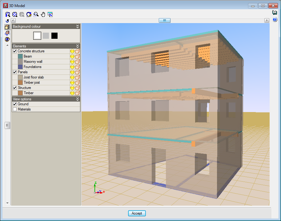
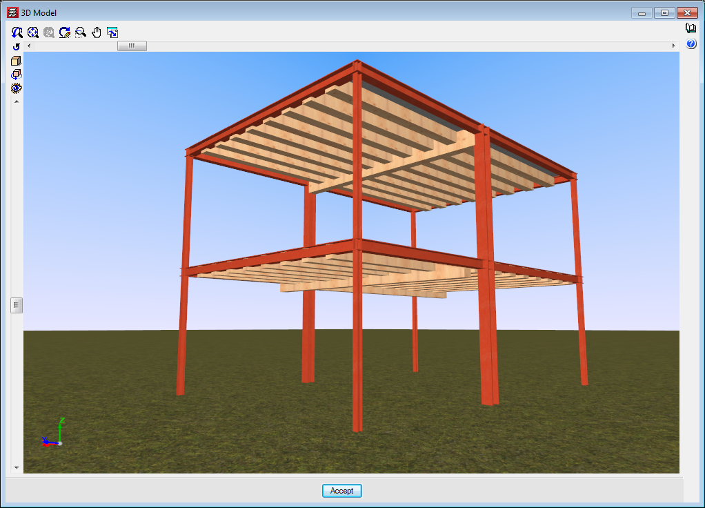
As of previous versions, users have been able to introduce “Generic” structural timber elements in integrated 3D structures in CYPECAD and CYPE 3D using the “Timber sections” module.

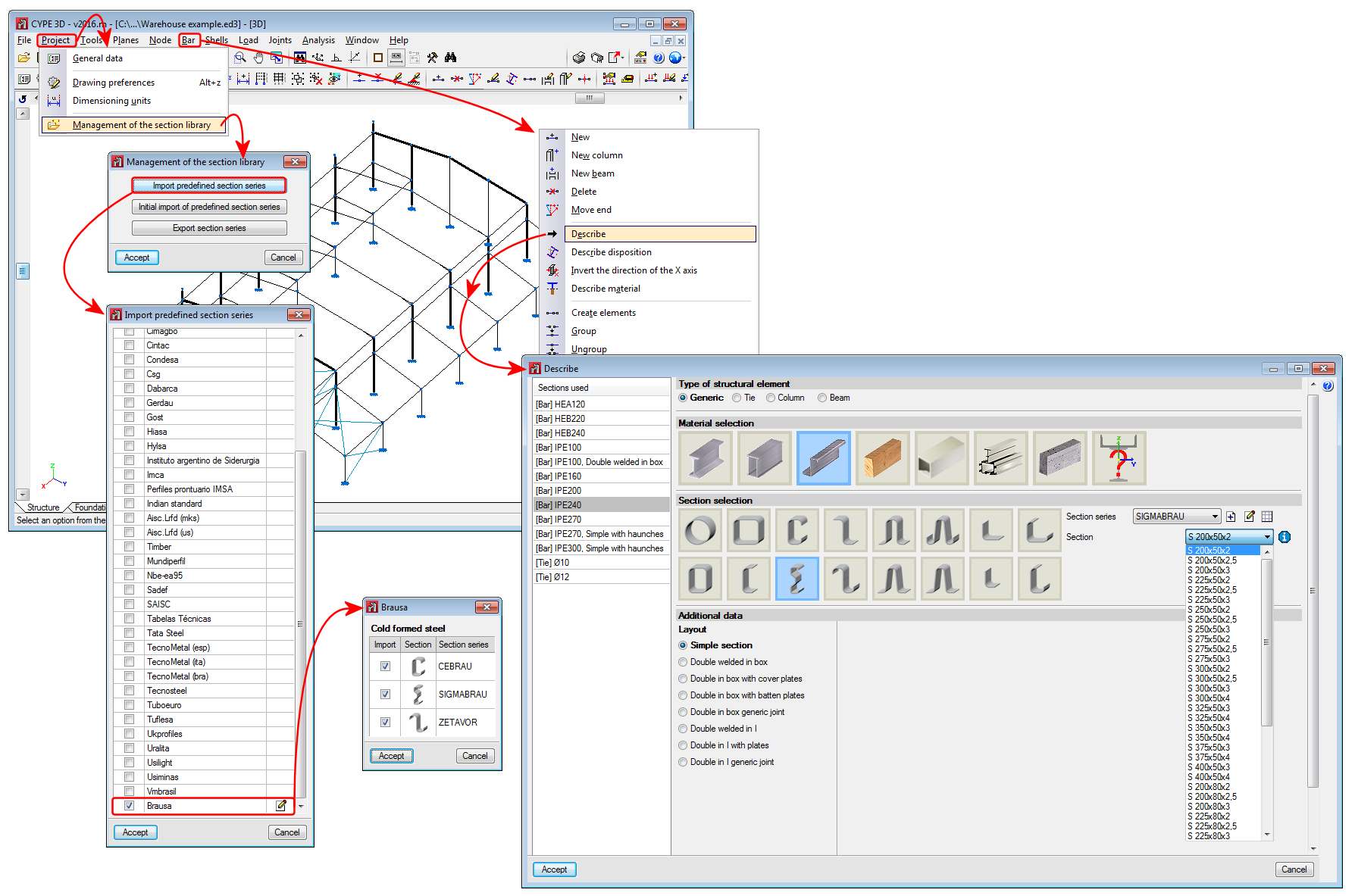
Further features have been added to the “Timber sections” module with the 2017.a version. Now, users can introduce beam-type timber elements in CYPECAD and CYPE 3D. By introducing the timber beams as that type of structural element instead of generic timber beams, allows specific beam checks to be carried out, and use the “Advanced beam editor” to edit and design these elements.

A summarised description of this new feature of the “Timber sections” module can be found in the “Timber beams” section of the new features of CYPECAD.

More information on the introduction, analysis and design of timber beams in CYPECAD and CYPE 3D can be found on the “Timber sections” webpage.

The steel IMCA sections (Instituto Mexicano de la Construcción de Acero) included in the CYPE 3D section library have been updated.

Trapezoidal loads can now be introduced on shells.

The BRAUSA cold-formed sections library has been included in the 2016.m version of CYPECAD, CYPE 3D and the Portal Frame Generator. The sections that have been included are:

  • CEBRAU: cold-formed stiffened U-section
  • SIGMABRAU: channel with stiffened web
  • ZETAVOR: cold-formed Z-section with stiffeners

As of the 2016.m version, users can export to the 21.1 version of Tekla Structures from CYPE 3D.

Reglamento para el Diseño Estructural Panameño 2014.

Implemented in CYPECAD and CYPE 3D.

The 2016.k version of the advanced column editor includes a button to reorganise columns in alphanumerical order. This order is that generated by default after analysing the job.

The seismic code of Peru (Norma Técnica E.030 (2014) Diseño Sismorresistente) has been implemented in CYPECAD and CYPE 3D.

When there are two shell edges with a shared node, if users indicate that the edges have free internal fixity, the shell will also be disconnected from the node.

Integration strips can be drawn when shells contain other shells. Their axes do not necessarily have to coincide; the program transforms the forces from the reference system of the contained shells to those of the container shell.

The zone corresponding to the contained shells are marked with a discontinuous rectangle.

This option is located in the Shells menu. It allows users to indicate a rotation angle with respect to the local x axis, by default. Using this option, the orientation of the axes of the shells can be adjusted.

This option is located in the Bar menu. It allows users to indicate whether a bar, if it crosses a shell, is to be connected to it or not. It does not affect the Shell-Bar interaction at an edge. Bars that are not connected to shells are displayed with a discontinuous line.

CYPE Mentor