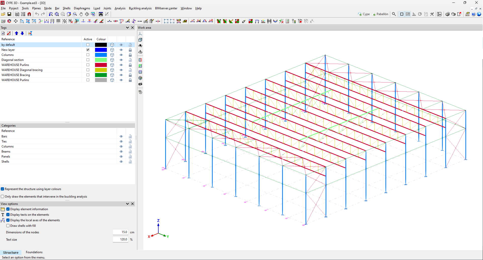
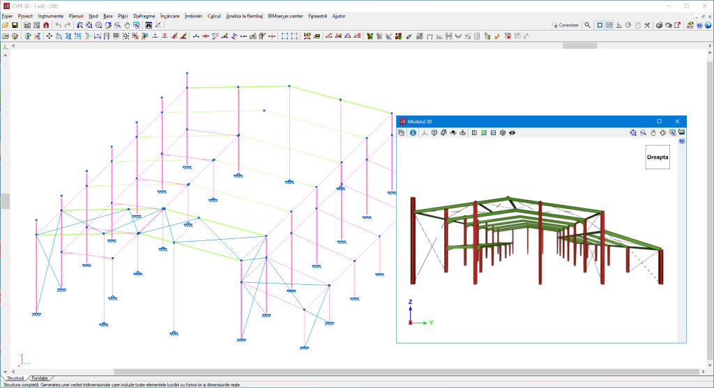
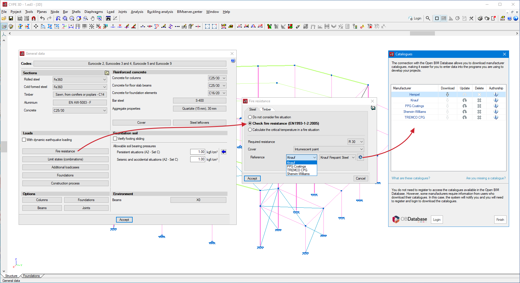
Update history​

CYPE 3D

Plastic hinges (new CYPE 3D module)

As of version 2024.f, plastic hinges can now be inserted into bars.

Using the new "Plastic hinges" option in the "Bar" menu, the relative position of the plastic hinges and their properties can be defined, as well as the rotational degrees of freedom in which they act.

Considering plastic hinges in the design of a structure requires a non-linear analysis using the OpenSees analysis engine. Therefore, users must have permission to use this analysis engine in their license, together with the "Plastic hinges" module.

More information on this CYPE 3D module can be found in the "Plastic hinges (new module)" new feature.

Improved CYPE 3D communication with StruBIM Steel and CYPE Connect

Up to version 2024.e, the import of CYPE 3D structures into StruBIM Steel or CYPE Connect was carried out from an IFC generated by CYPE 3D.

With this improvement in version 2024.f, this communication will be carried out by exporting and importing an exchange file in JSON format, which will allow more efficient communication and accurately reflect the specific features of a CYPE 3D structure.

Updating the CYPE Menu applications

As of version 2024.f, the CYPE Menu tool (available on the BIMserver.centre platform Store) allows users to manage the updates of the applications it includes.

When accessing the CYPE Menu, the program checks whether there is a newer version of the installed applications and, if so, the "Update" option appears next to them.

The update process will download the application and, once completed, will start the installation.

Snappable or non-snappable layers

As of version 2024.e, users can now select whether the elements of each layer are snappable or non-snappable.

In "Layer management" the "Snappable" column has been added.

When this option is unchecked in any layer, the elements belonging to that layer cannot be snapped.

Warning for assigning buckling coefficients

Up until version 2024.e, when buckling coefficients were assigned, bars that did not participate in any buckling mode were assigned a buckling coefficient equal to zero.

As of version 2024.e a warning will be displayed, after the buckling coefficient assignment process, and the buckling coefficients of the bars that do not have a participation percentage higher than the minimum percentage in all analysed modes will not be updated.

Buckling analysis in shells

As of version 2024.e, users can now analyse the buckling behaviour of shells. To do this, the "Buckling" option has been included in the "Shells" menu.

With this option, the shells to be considered in the linear buckling analysis can be marked.

Also, in the "Buckling analysis" menu, the "Buckling contour plots of the active window" option has been added.

Once the buckling analysis has been carried out, this option allows users to view the contour plots of the deformed shape in the different modes.

Exporting and importing rotational stiffnesses

Version 2024.e implements the export of the rotational stiffnesses of the connections in CYPE Connect and StruBIM Steel. The import of rotational stiffnesses is also implemented in CYPE 3D.

This improvement allows the rotational stiffness of connections analysed in CYPE Connect or StruBIM Steel to be considered in the original CYPE 3D structure.

The export occurs when there are connections with analysed rotational stiffness and is exported to BIMserver.center.

In CYPE 3D, the corresponding contribution must be imported from the menu "BIMserver.center > Consult", activating the "Update the rotational stiffness of the element ends" option.

Optional consideration of bar eccentricities in the analysis

Up until version 2024.e, the eccentricities defined in bars from "Bar > Describe disposition" always affected the design model.

As of version 2024.e, users can now choose whether or not to take eccentricities into account in the analysis.

When the option is not activated in a bar, this bar is considered to be centred in the design model.

Shortcuts for all applications

CYPE apps have keyboard shortcuts common to all programs. In versions before 2024.e, each program displayed the keyboard shortcuts for each app via the "Search and activation of commands and options" in the top left-hand corner of the programs.

As of version 2024.e, the "Shortcuts for all applications" tab has been implemented in the dialogue box displayed when selecting this option and it shows all the keyboard shortcuts common to CYPE apps.

Shells with orthotropic material. Assistant for entering CLT panel properties

In version 2024.c, the possibility of defining orthotropic materials for designing shells was added to CYPE 3D. As of version 2024.d, a tool is included to make it easier to enter the data specified by a CLT panel manufacturer in their European Technical Assessment document.

Fixity at bar ends

Up until version 2024.d, CYPE 3D allowed users to edit the fixity at bar ends in the XY and XZ planes.

As of version 2024.d, the degree of fixity in the YZ plane can also be edited. Each end can be assigned a fixity coefficient (0 for the hinged end; 1 for the fixed end) or a rotational stiffness can be assigned.

Buckling analysis (global stability) (new module)

As of version 2024.d, users can carry out the linear buckling analysis. The linear buckling analysis allows the critical load factors and the buckling deformations of the structure to be determined for each analysed combination by solving an eigenvalue problem.

In order to carry out this analysis, the user's license must have the necessary permission for this module and for the "OpenSees analysis engine".

Before solving this problem, a static analysis of the defined combinations is carried out. The result of this analysis allows users to determine both the axial compression forces of each bar and the behaviour of the non-linear elements for each combination.

Once the buckling analysis has been carried out, a participation analysis is performed to determine the influence of a buckling mode on the bars in the structure. To obtain it, a participation percentage of 100% is assigned to the bar that absorbs the greatest deformation energy in that mode and, for the rest of the bars, it is calculated as the quotient between their deformation energy and that of the previously mentioned bar.

The options related to this new feature can be found in the new "Buckling analysis" menu.

Combinations for the buckling analysis

The stability of the structure must be analysed by load combinations. Just as for the non-linear analysis, the load combinations are defined based on the loadcases defined in the job data.

The program allows users to define the combinations to be analysed in three ways:

  1. By manually entering each combination.

  2. By automatically generating all possible combinations from the situations defined in the project.

  3. By analysing the results obtained from a linear analysis. In this case, the combinations in which the highest axial compression is produced are added to the bars of the structure depending on user-defined conditions.

Analysis

For the buckling analysis, users can define the number of buckling modes to be analysed and filter them by the maximum eigenvalue. The number of discretisation spans of the bars or the maximum length of each span can also be set.

For steel bars, users may indicate the minimum percentage of axial compression force below which a bar will not be included in the buckling analysis.

Assigning buckling coefficients

The program automatically analyses the buckling coefficients for each bar considered in the analysis. These coefficients can be assigned immediately after the buckling analysis, or by means of the "Assign buckling coefficients" option.

From the factors of both the critical load and the acting axial force, the program assigns the buckling coefficients. The participation analysis allows the buckling modes affecting each bar to be determined in order to analyse and assign the buckling coefficients.

Viewing the results

The buckling analysis results can be checked for each combination and buckling mode through the "Buckling modes" option. The program allows users to visualise both the deformation and the participation coefficient of each bar.

Buckling in bars

When defining the buckling data of a bar, users can indicate whether or not it will participate in the buckling analysis and, in case of updating the coefficients from the analysis results, which buckling coefficients will be updated.

Reports

The program allows the following reports to be generated:

  • Buckling modes by analysis combination.
  • Extended report of buckling modes for each bar.
  • Summary report of the most influential buckling modes for each bar.