ASCE/SEI 7-16: Minimum Design Loads for Buildings and Other Structures.
Implemented in CYPECAD.


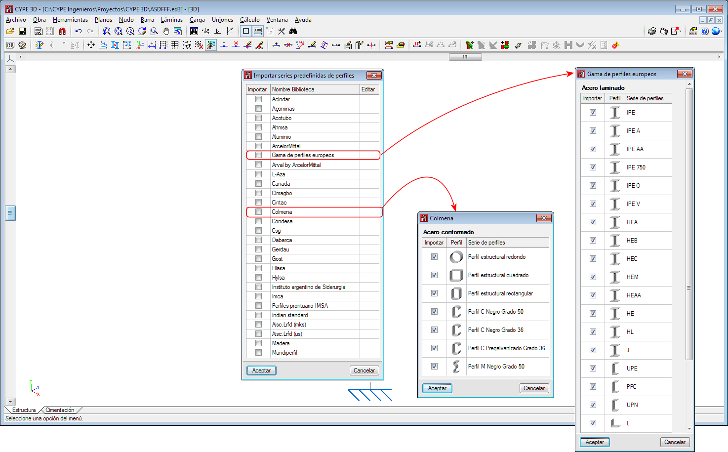
Two new section libraries have been implemented:
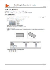
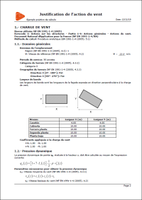
In the 2020.c version, the “Wind load justification report” has been implemented for the following codes:
This report was implemented for other codes in previous versions and will continue to be implemented for others progressively.
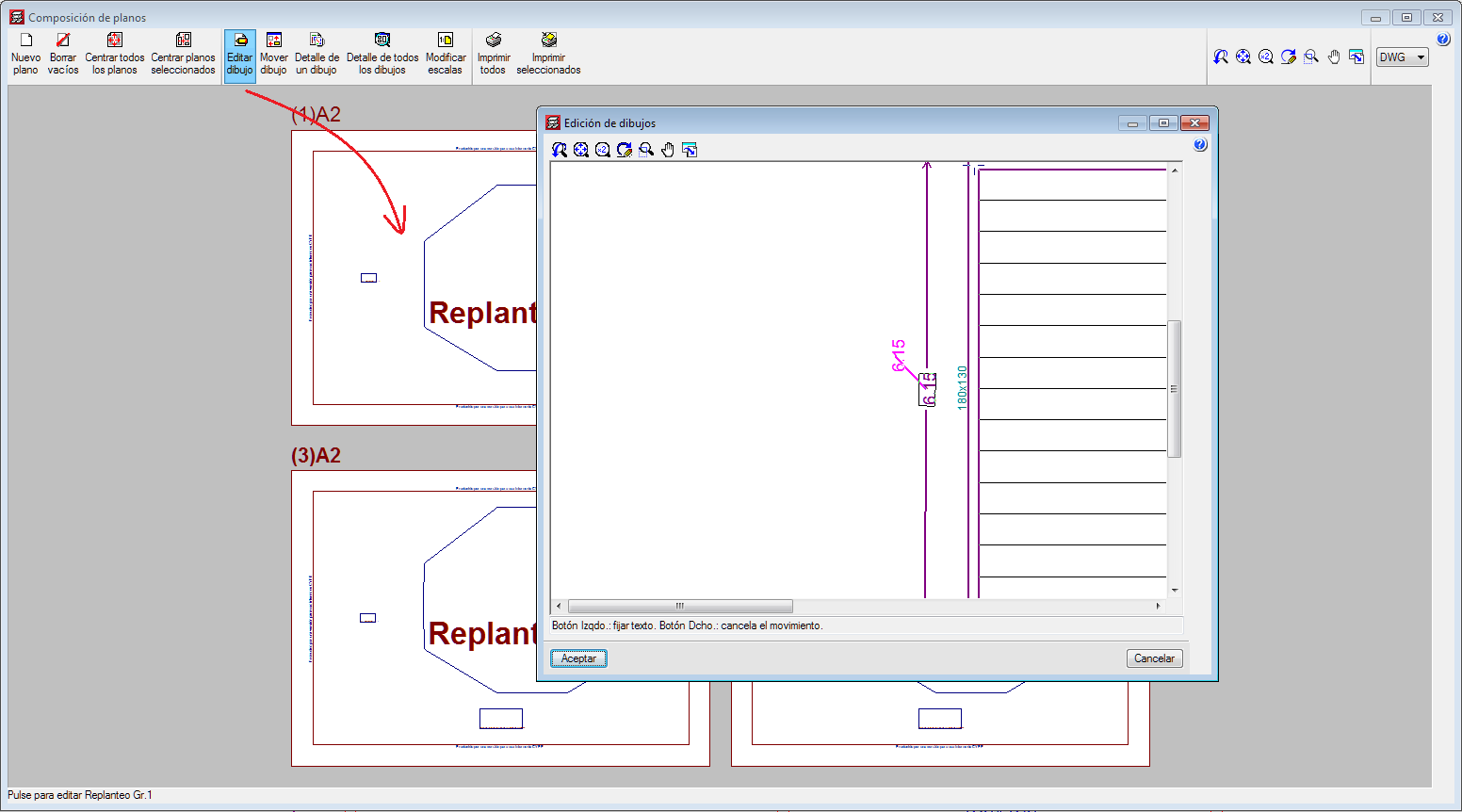
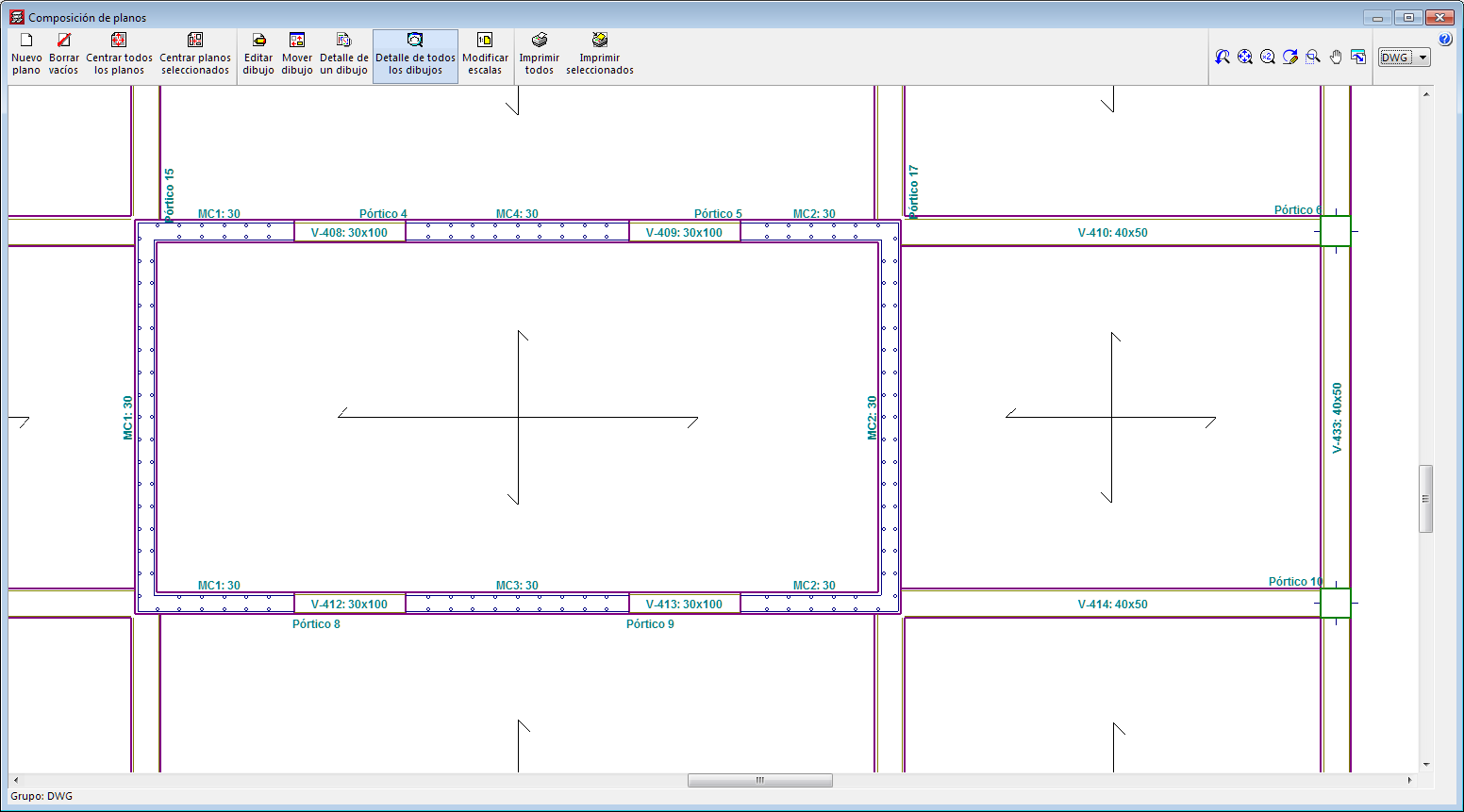
A new option has been implemented to change the position of texts that have been defined using the “Editing resources” tools from the “Drawing editor” of the “Drawing composition”.
Some options (Options, Reorganise, Assign number, Assign reference and Multiple assignment) have been grouped or added in the “Beam alignment” panel (“Beam Definition” > Beams > Beam alignments).
Please note that, as of the 2020.c version, beam alignment references will remain even if beams are added or deleted.
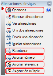
Options
The following existing tools have been grouped in Options:
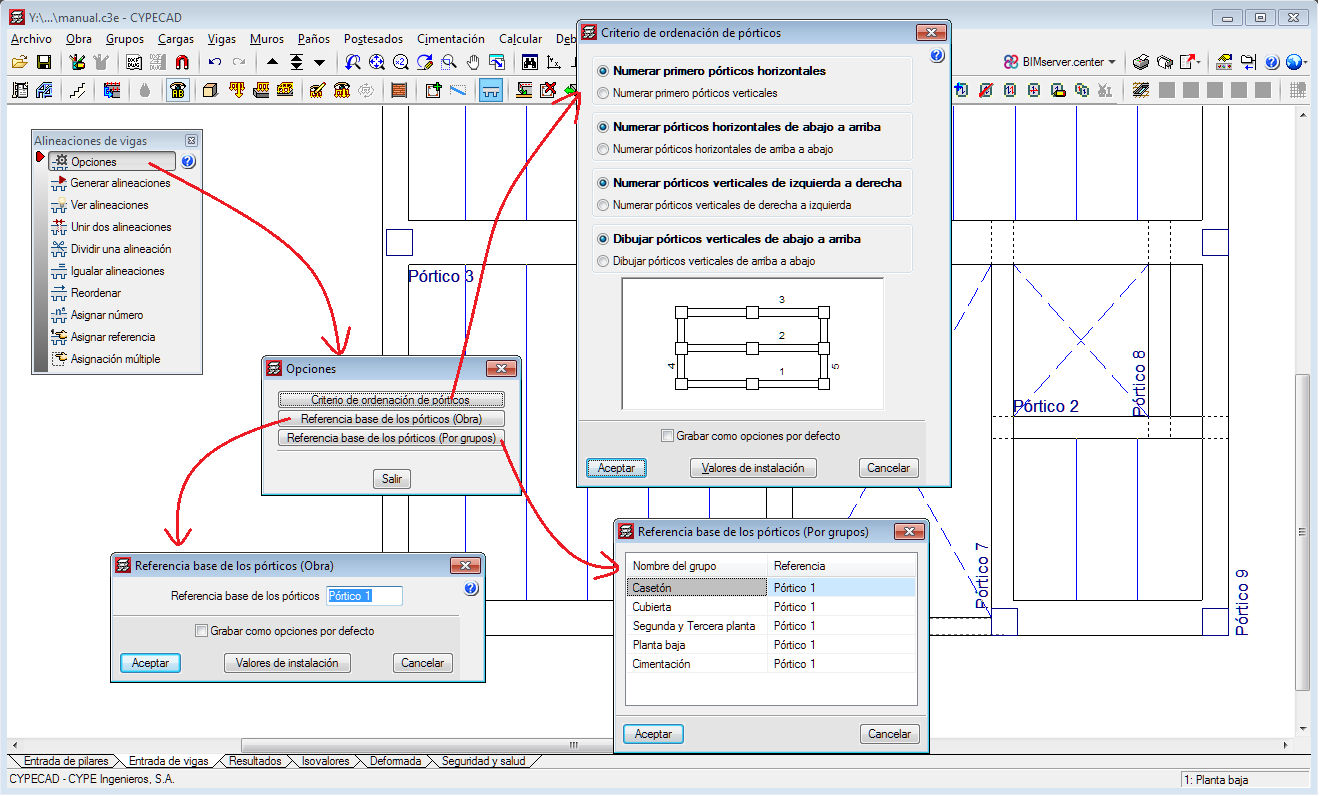
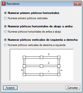
Reorganise
Using this tool, users can reorganise the frames depending on their position on-plan.
Assign number
This option allows users to assign a different alignment or frame number to the one that has been generated automatically by the program in accordance with the criteria that has been specified in “Generate alignments”.
Assign reference
With this option, users can assign a reference to an alignment.
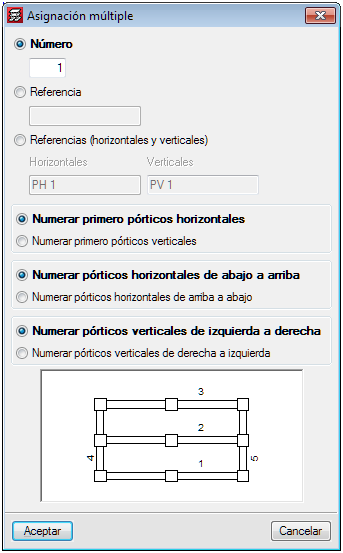
Multiple assignment
Using this tool, users can assign the following data to a selection of alignments:
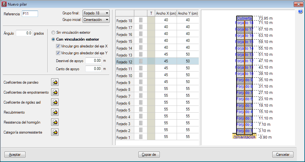
The appearance of the dialogue box where columns are introduced and edited has been modified. The table where users can edit the geometry of the column at each floor has been moved to the right of the column data.
With the distribution that existed in previous version, users could not view all floors simultaneously if the structure contained a high number of floors.
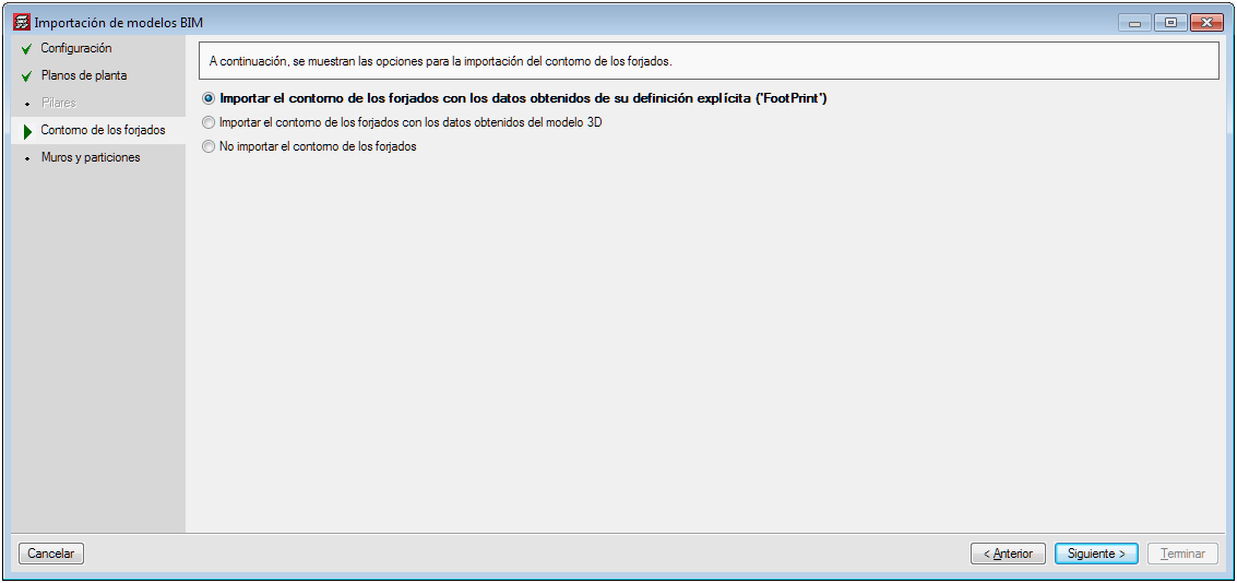
Several options have been implemented in CYPECAD to import floor slab outlines:
The architectural models can contain different information depending on the program and the program version that has generated them. Some programs export the floor plan representation of the floor slabs (FootPrint) as well as the 3D model. Up until the 2020.b version, CYPECAD imported the representation of the floor slabs (FootPrint) if it had been defined, otherwise, it offered users the possibility to import them based on the 3D model.
These import options have been implemented because errors were observed in the IFCs that came from the latest versions of some programs, where the outlines were exported correctly but the outlines of the openings were not exported
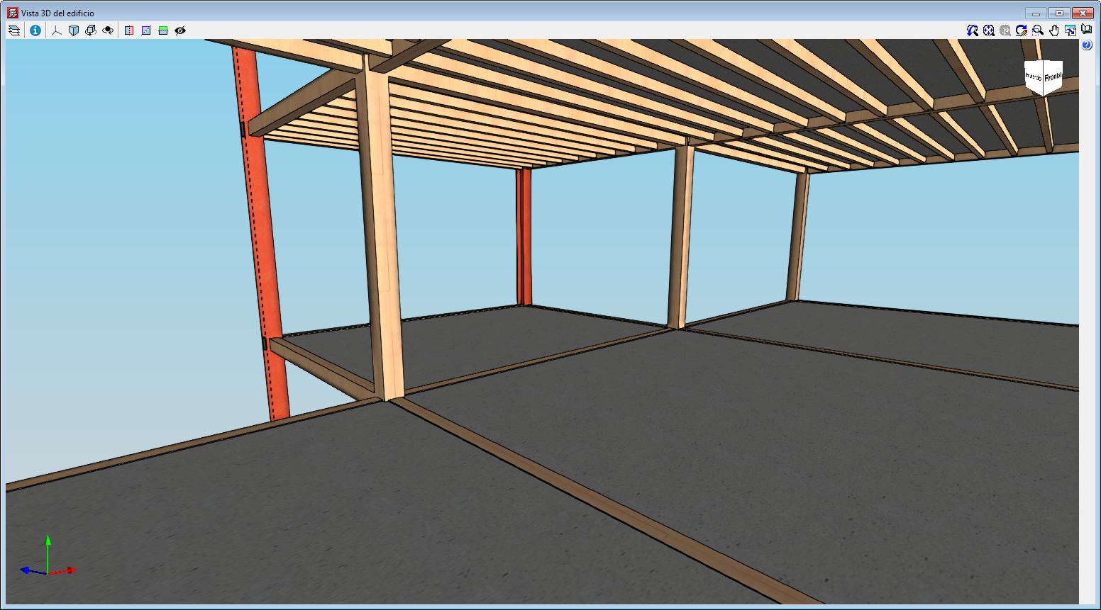
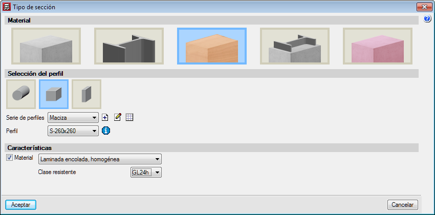
With the “Timber columns” module, CYPECAD can analyse and design timber columns with rectangular and circular sections.
The codes that have been implemented to design and check timber columns are:
More information on Timber columns.
In the 2020.b version of CYPECAD, tags of shear walls that have been defined by users can now be represented on floor plan drawings.
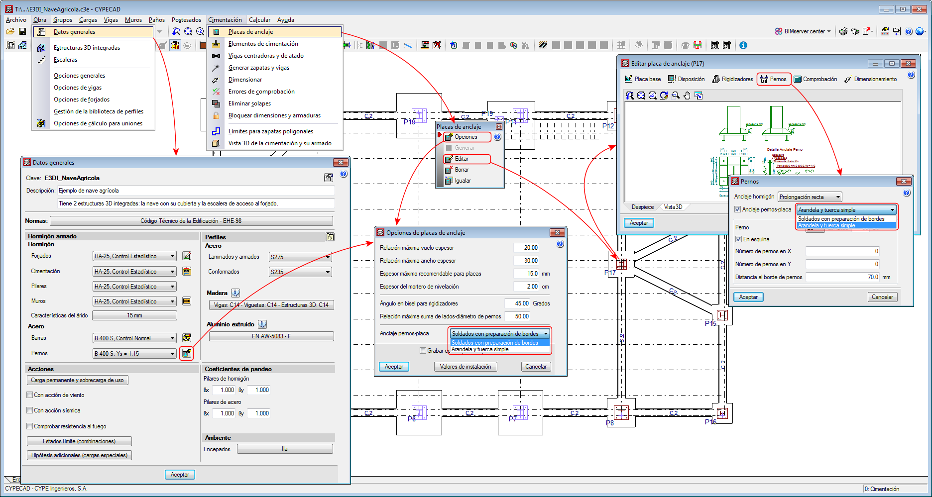
Users can now edit the bolt to baseplate connection method for each baseplate.
Up until the 2020.a version, only one connection system could be selected for all the project (Project > General data).
As of the 2020.b version, when users edit an individual baseplate (Foundations > Baseplates > Edit), they can change the connection system between the bolts and the baseplate (“Bolts” button > “Bolts-baseplate anchorage” option).
In the 2020.b version, users can also define the connection system between bolts and the general baseplate of the project from “Foundations” > “Baseplates” > “Options”.