As of the 2019.a version, the “Reinforcement quantities, by diameter” report can show the reinforcement by diameter summary, by group.
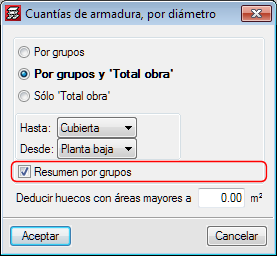
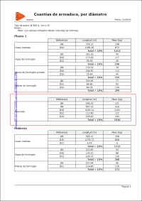


As of the 2019.a version, the “Reinforcement quantities, by diameter” report can show the reinforcement by diameter summary, by group.
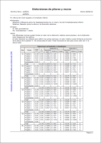
As of the 2019.a version, the “Column distortions” report is called “Column and wall distortions”. This report, in previous versions, only included column distortions. As of this version, the distortions of walls connected to the rigid diaphragm of the floor also appear in the report.
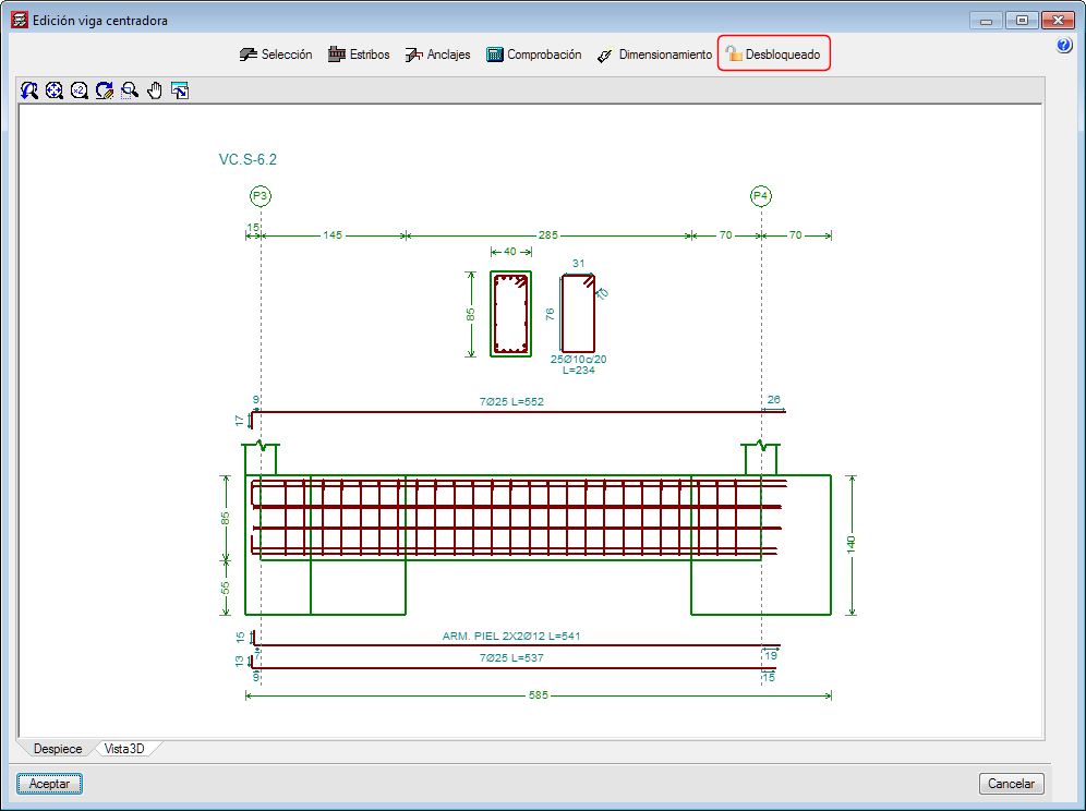
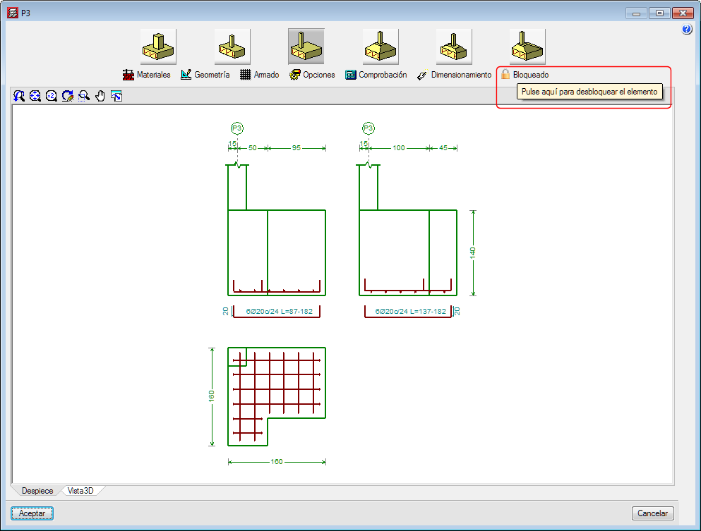
As of the 2019.a version, it is possible to block the dimensions and reinforcement of footings, pile caps, and strap and tie beams so that they do not undergo any changes during the foundation design process.
The “Block/Unblock” option has been implemented in the “Foundation” menu of the “Beam Definition” and “Results” tab. When selected, users can choose which elements are to be blocked or unblocked. The option to block or unblock is also available in the “Foundation elements” editing window (footings and pile caps) and “Strap and tie beams”.
As of the 2019.a version, CYPECAD and CYPE 3D can take into account the effects of the vertical seismic component by considering them as a percentage of the gravitational effect. Optionally, both programs apply a modification or adjustment coefficient that acts as the sum of the factor of the permanent loads in the seismic force combinations.
This coefficient increases the factor of the permanent loads in seismic combinations for unfavourable gravitational conditions and decreases the factor of the permanent loads for favourable gravitational conditions. In the first case, the gravitational effects are added to the seismic effects. In the latter, the gravitational effects counteract the seismic effects.
Consideration of the effects of the vertical seismic component
In building design, it is usual to calculate a structure to against the horizontal action of the earthquake and neglect the effects of the vertical component. However, in certain cases, it is advisable to consider these effects in the design.
CYPECAD and CYPE 3D apply an alternative procedure to the specification of spectra to consider the vertical seismic action, including its effects in seismic combinations by increasing the effect of the permanent load. This increase takes positive and negative values, due to the reversibility of the seismic action, and increases and decreases the gravitational effects in the combination. By doing so, the effects of vertical movement of the floor in buildings are simulated, such as:
CYPECAD and CYPE 3D propose a simple calculation for this modification coefficient, which provides a value that adapts to what is established in the standards and that is a function of the seismicity of the site that has been selected by the user. Some codes call it "vertical seismic pseudo-acceleration", but it does not represent the total vertical response, only the part that is combined with the horizontal response and the effects of gravity. The data proposed by the program can be modified by users, since different situations to those usually contemplated by the standards may arise.
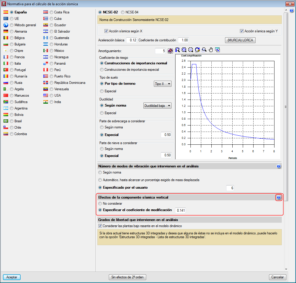
In the section of the seismic data dialogue where users can activate whether or not the effects of the vertical seismic component are to be considered, there is a help button where more information on the calculation of the "vertical seismic pseudo-acceleration" coefficient can be found.
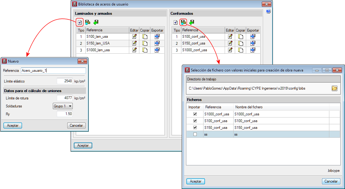
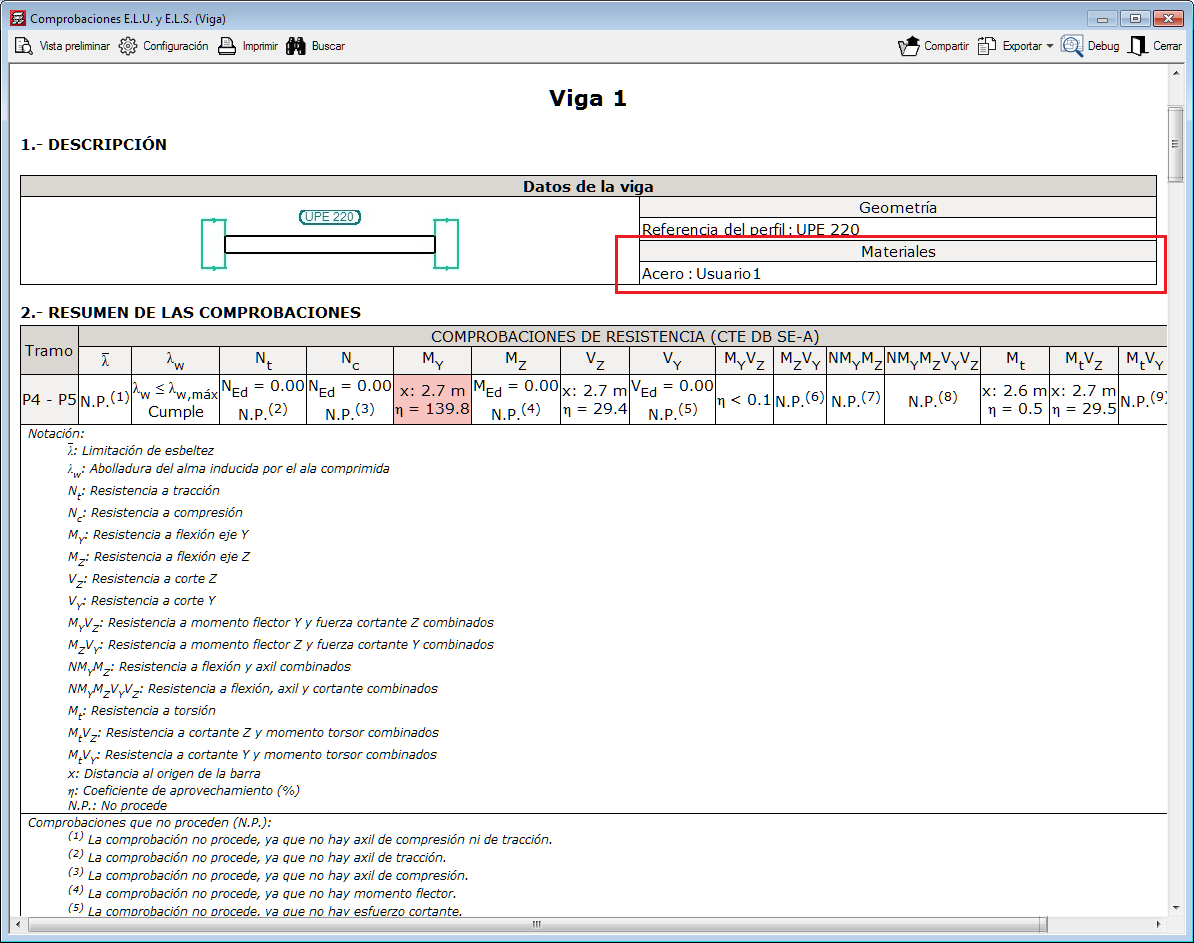
In the 2019.a version of CYPECAD and CYPE 3D, users can now define steels for which they can indicate their elastic limit. The modulus of elasticity, thermal expansion coefficient, density and Poisson's ratio are defined internally by the program using the values of the steel. For U.L.S. checklists, the type of steel that is used can be seen.
As well as the elastic limit and depending on the selected code, additional data may be required to design connections.
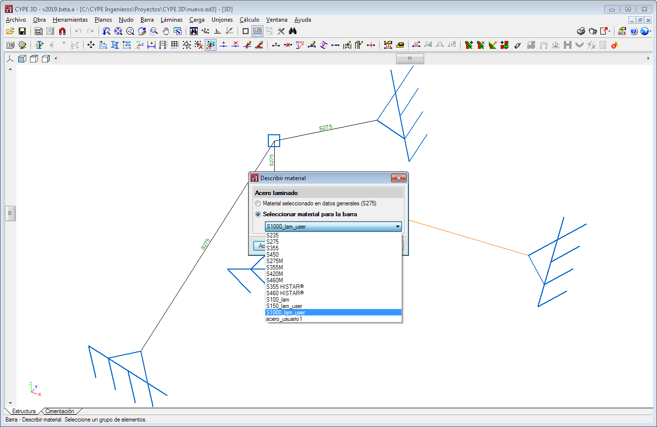
The user steel library can be accessed from General Data. Rolled or cold-formed steel can be assigned to the sections as can steels that are established by each standard.
User-defined steels can be exported to the library to be used in other projects. They can also be selected as initial steels for the creation of new projects. The library is common to CYPECAD and CYPE 3D.


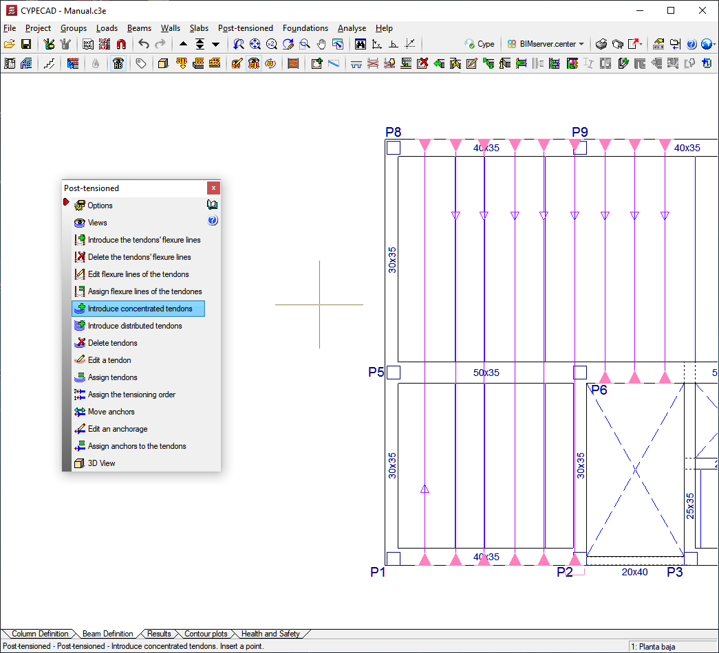
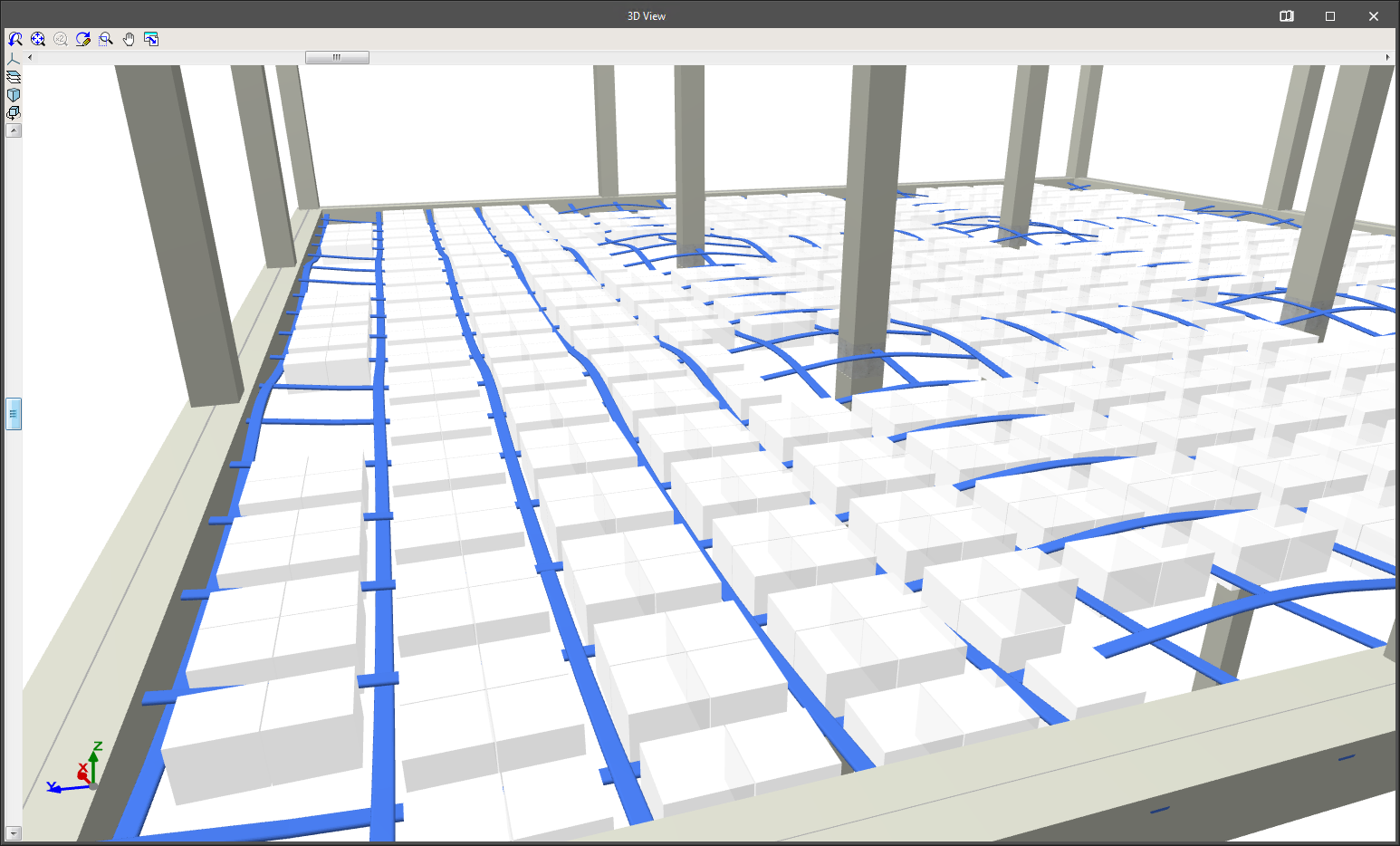
The CYPECAD module: "Post-tensioned waffle and joist floor slabs" allows users to design the passive reinforcement of waffle slabs, in-situ joist floor slabs and their perimeter beams, after calculating the forces of the post-tensioned tendons (adherent or non-adherent) and whose properties have been introduced by users.
This module allows users to introduce the layout of the tendons, their definition, stressing loads and percentage losses (instantaneous and deferred). The program generates two post-tensioned loadcases (one with instantaneous losses and the other with total losses: instantaneous + deferred) in which it will introduce the deviation loads that are produced due to the path of the tendons.
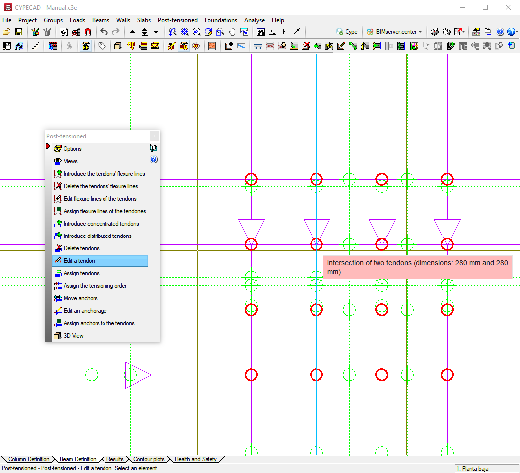
During the reinforcement design phase of the waffle slabs and, if the tendons have been defined as adherent, the contribution of the remaining or excess capacity of the active reinforcement is taken into account, which is subtracted to determine the passive reinforcement.
The functionality of the tools for introducing and editing bending lines and tendons is the same as for Post-tensioned slabs for building.
In order for CYPECAD to be able to carry out the indicated calculations for post-tensioned waffle slabs and joist floor slabs, the user license must include the permits for the “Post-tensioned waffle slabs and joist floor slabs” module.

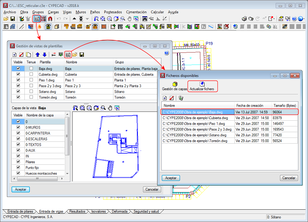
As of the 2018.l version, all the drawing templates of the project with changes can be updated using the “F2” key.
Templates are also updated when they are viewed for the first time since the project has been opened or they can be updated manually (one by one) from the “Available files” dialogue box (as shown in the image).
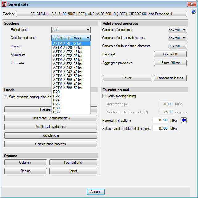
The following types of steel have been incorporated to the AISI S100-2007 cold-formed steel code: F-20, F-22, F-24, F-26, F-30 and F-36 (of common use in Argentina).
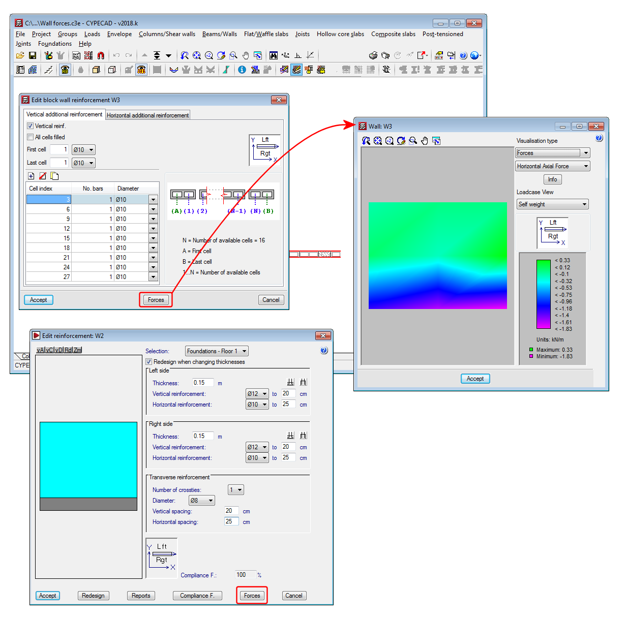
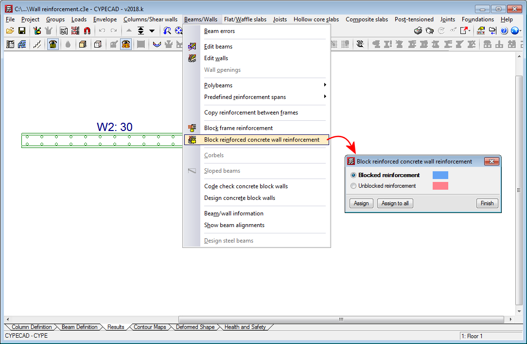
The 2018.k version allows users to block the reinforcement of reinforced concrete walls. To do so, a new option has been implemented: “Block reinforced concrete wall reinforcement” in the “Beams/Walls” menu of the “Results” tab. This option opens a dialogue box in which users can assign a “Blocked reinforcement” or “Unblocked reinforcement” property to reinforced concrete walls. The reinforcement of walls that have been assigned the “Blocked reinforcement” property will not change during the design process.
As of the 2018.k version, users can consult the forces in walls in the “Edit reinforced concrete wall reinforcement” and “Edit block wall reinforcement” windows. To do so, both dialogue boxes include the new “Forces” button, which provides access to the force consultation dialogue box of the selected wall.