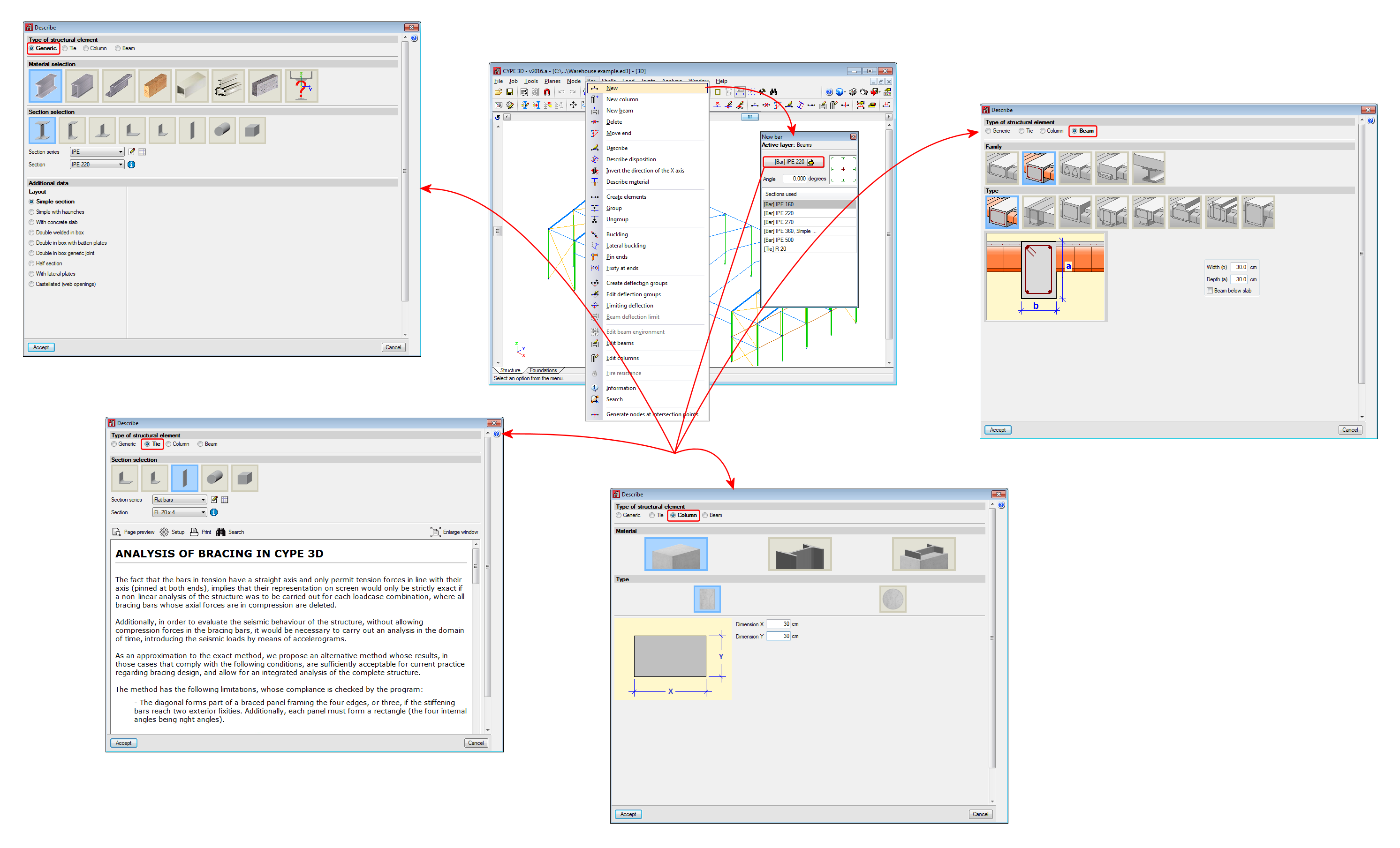
As of version 2016.a, CYPE 3D now requires you to understand the structural function carried out by a part. Four different structural typologies can be assigned:
- Generic
The part has no structural role known to the program. It will be designed, edited and checked like parts prior to this version. - Tie rod
The element is part of a braced frame and only works in tension. This was already present in previous versions. - Column
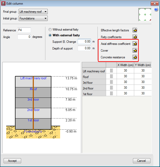
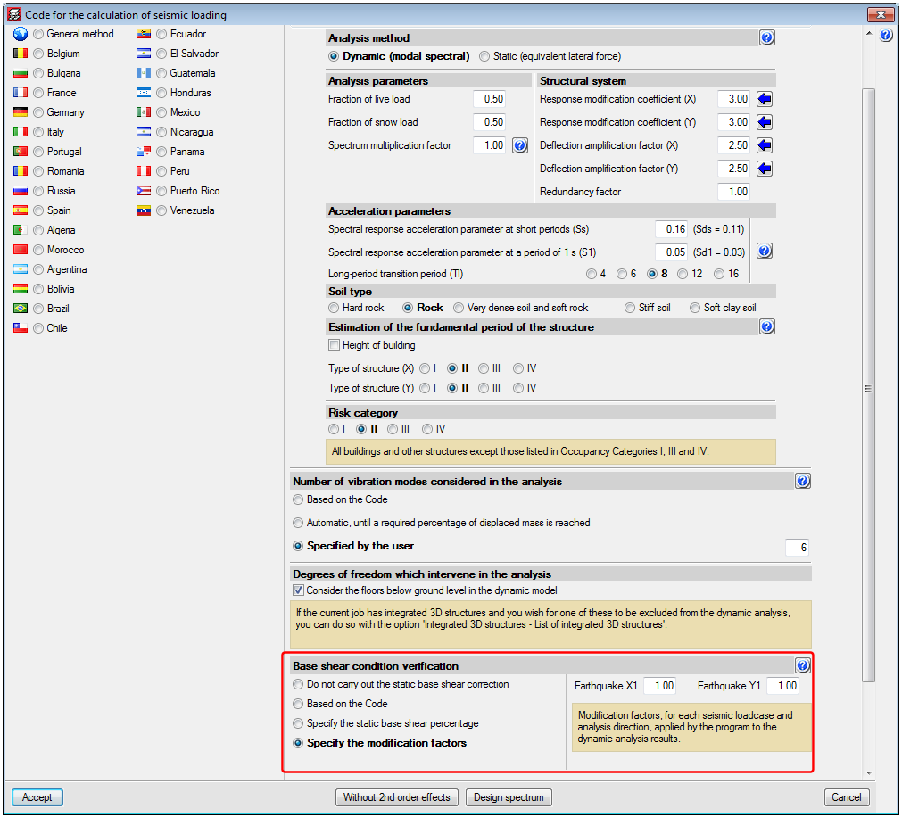
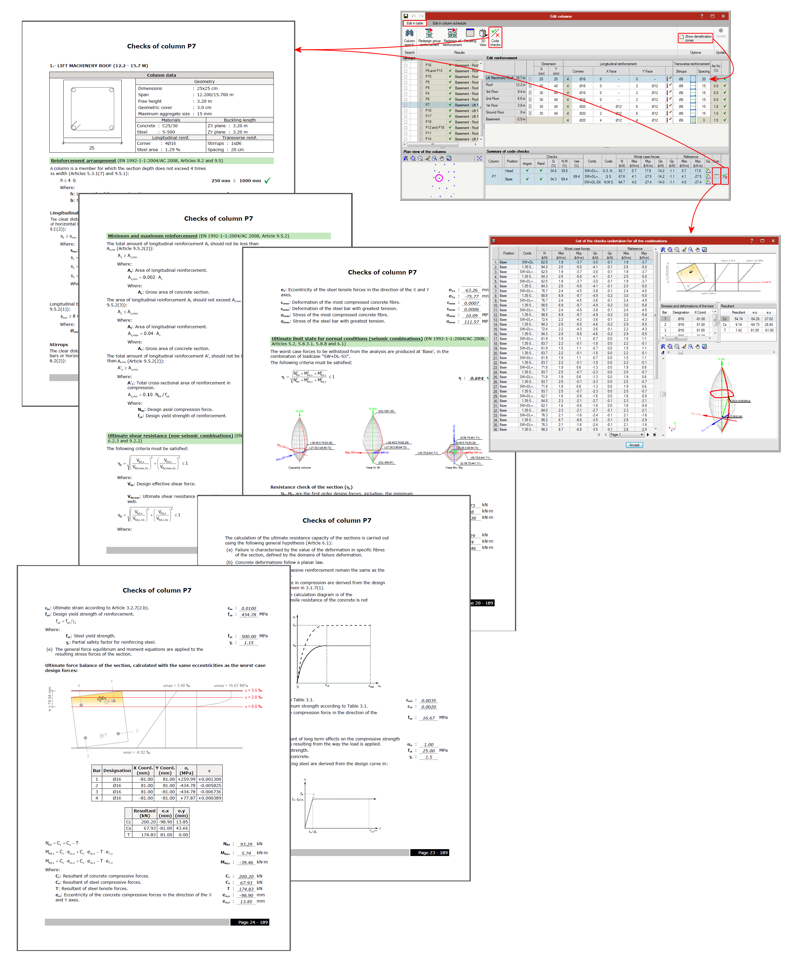
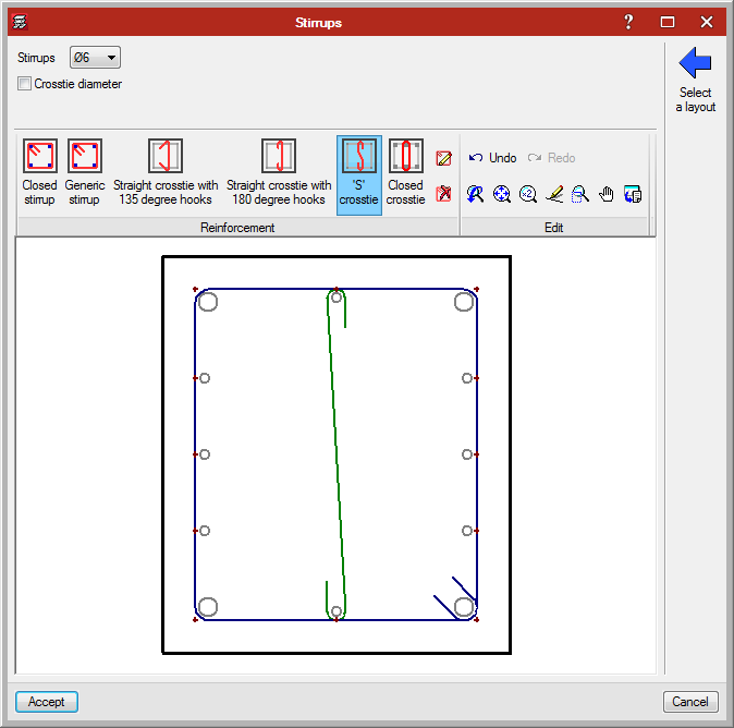
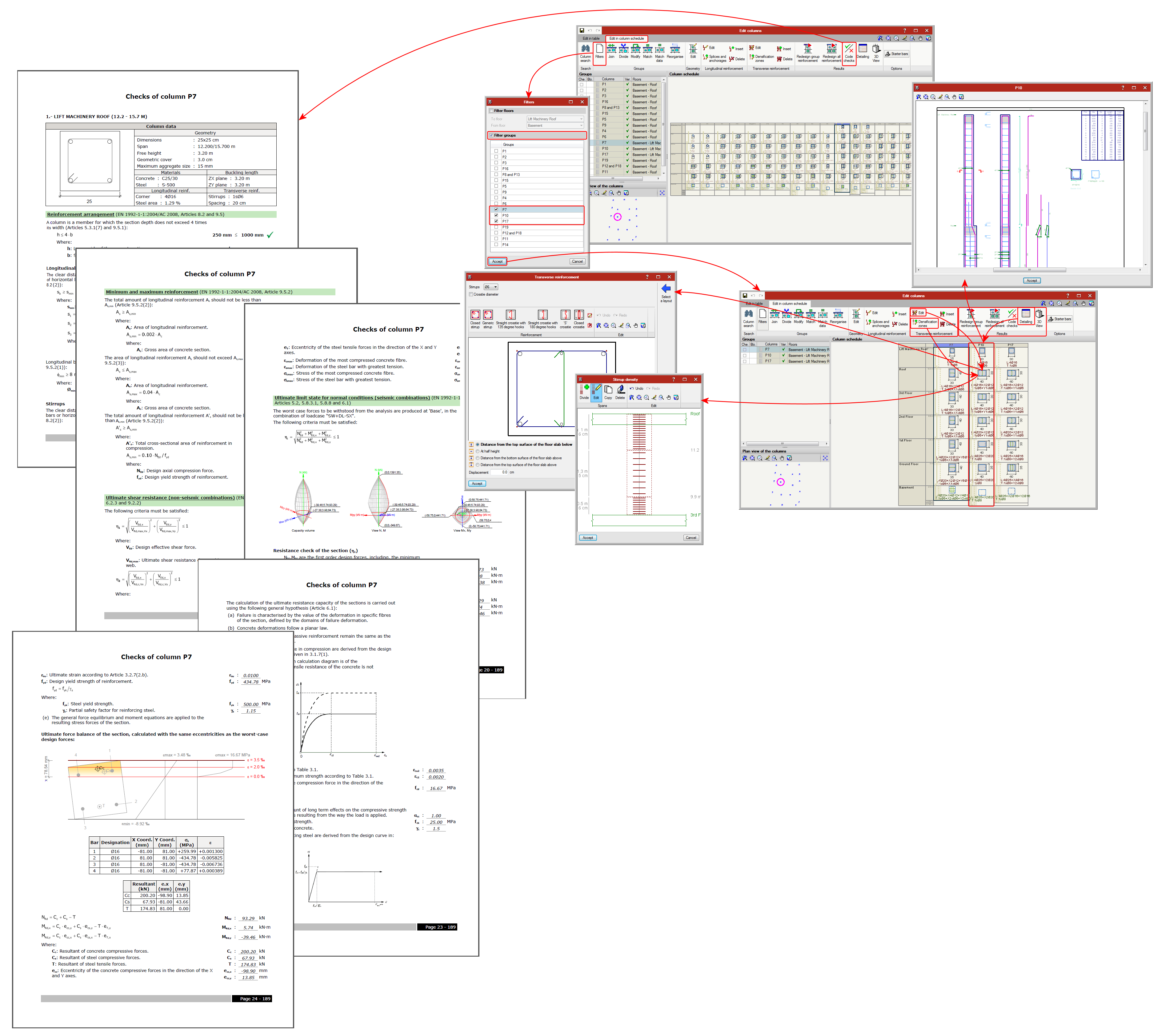
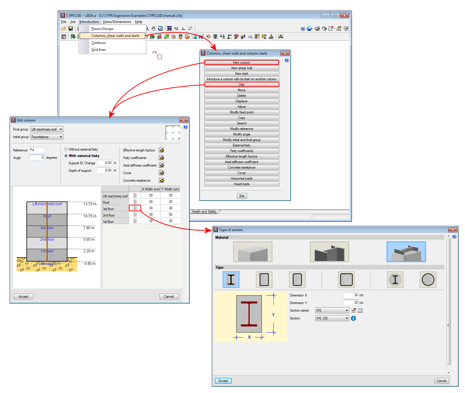
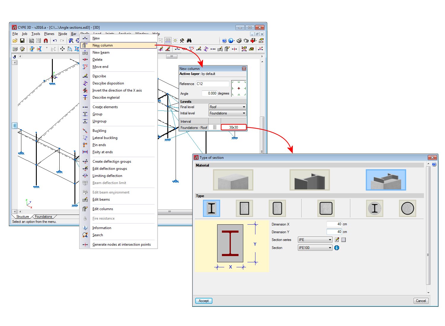
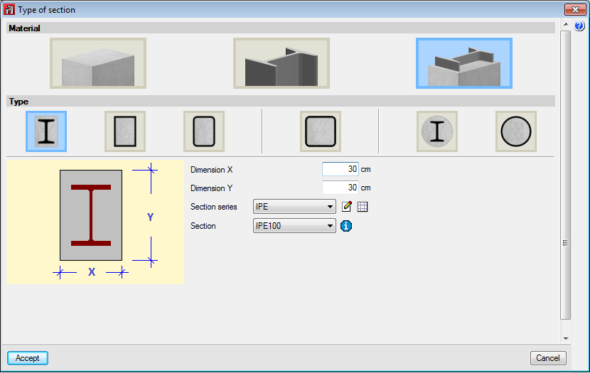
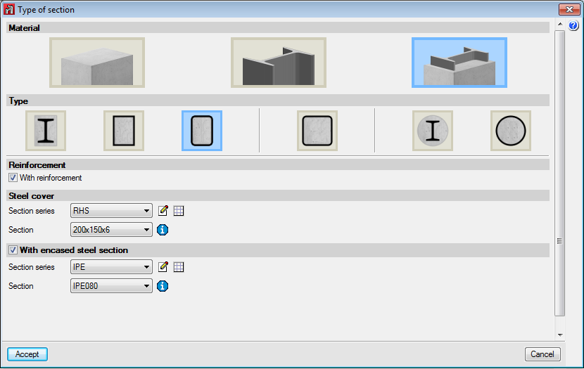
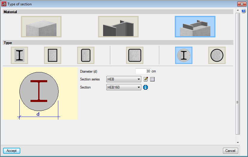
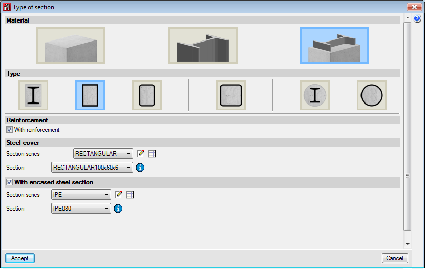
The element is a column. Its design, editing and check are carried out via the Advanced column editor, so it can only be designed for the codes that are implemented in this editor. Normally, revoked or repealed concrete codes are the ones that are not available in this editor. The sections it supports are the following:- Rectangular and circular reinforced concrete sections
Further information about this module, which is common to both CYPE 3D and CYPECAD and allows both programs to design these structural elements, can be found on the Concrete columns webpage. - Steel sections
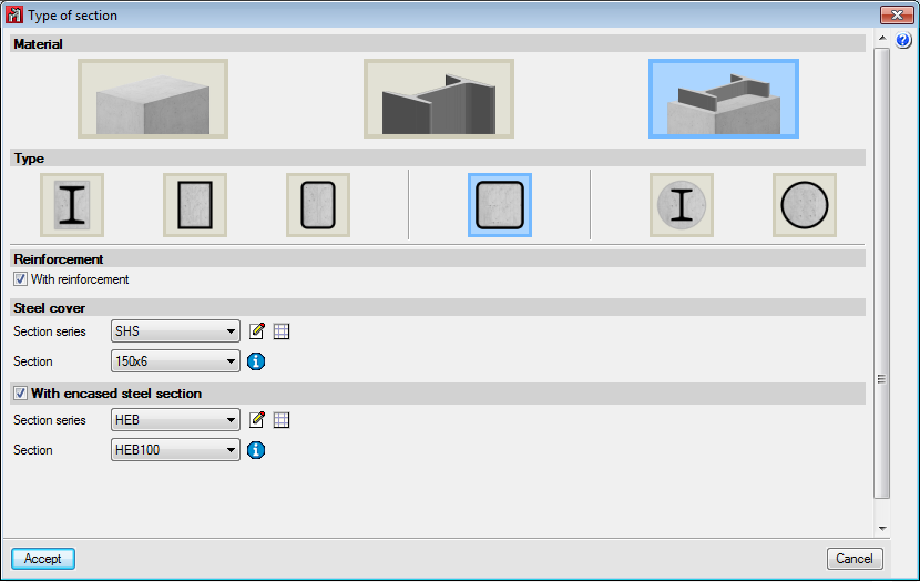
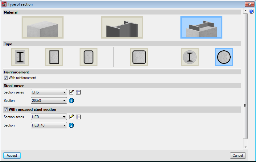
These can be made of rolled, reinforced or cold-formed steel sections. - Concrete-steel composite sections
Further information about this module, which is common to both CYPE 3D and CYPECAD and allows both programs to design these structural elements, can be found on the Composite steel and concrete columns webpage.
More information about these structural elements can be found in the Properties of column-type structural elements section on this same webpage.
- Rectangular and circular reinforced concrete sections
- Beam
The element is a beam. Its design, editing and check are carried out via the Advanced beam editor so it can only be designed for the codes that are implemented in this editor. The sections it supports are the following:- Rectangular reinforced concrete section beams, ‘L’ or ‘T’ beams, lattice beams or prestressed beams
Further information about this module, which is common to both CYPE 3D and CYPECAD and allows both programs to design these structural elements, can be found on the Concrete beams webpage. - Steel sections
These can be made of rolled, reinforced or cold-formed steel sections.
When an element is defined as a beam, the beam is composed of a single element. However, the program allows continuous beams made up of several beams to be defined.
More information about these structural elements can be found in the Properties of beam-type structural elements section on this same webpage.
- Rectangular reinforced concrete section beams, ‘L’ or ‘T’ beams, lattice beams or prestressed beams