Update history
CYPECAD
BRAUSA cold-formed sections library
- Published on
- 2016.m
Code implementation. REP 2014 (Panama)
- Published on
- 2016.l
Advanced column editor
- Published on
- 2016.k
Seismic code of Peru
The seismic code of Peru (Norma Técnica E.030 (2014) Diseño Sismorresistente) has been implemented in CYPECAD and CYPE 3D.
- Published on
- 2016.k
Bar menu. Introducing bars as a structural element
As of version 2016.a, CYPE 3D now requires you to understand the structural function carried out by a part. Four different structural typologies can be assigned:
- Generic
The part has no structural role known to the program. It will be designed, edited and checked like parts prior to this version. - Tie rod
The element is part of a braced frame and only works in tension. This was already present in previous versions. - Column
The element is a column. Its design, editing and check are carried out via the Advanced column editor, so it can only be designed for the codes that are implemented in this editor. Normally, revoked or repealed concrete codes are the ones that are not available in this editor. The sections it supports are the following:- Rectangular and circular reinforced concrete sections
Further information about this module, which is common to both CYPE 3D and CYPECAD and allows both programs to design these structural elements, can be found on the Concrete columns webpage. - Steel sections
These can be made of rolled, reinforced or cold-formed steel sections. - Concrete-steel composite sections
Further information about this module, which is common to both CYPE 3D and CYPECAD and allows both programs to design these structural elements, can be found on the Composite steel and concrete columns webpage.
More information about these structural elements can be found in the Properties of column-type structural elements section on this same webpage.
- Rectangular and circular reinforced concrete sections
- Beam
The element is a beam. Its design, editing and check are carried out via the Advanced beam editor so it can only be designed for the codes that are implemented in this editor. The sections it supports are the following:- Rectangular reinforced concrete section beams, ‘L’ or ‘T’ beams, lattice beams or prestressed beams
Further information about this module, which is common to both CYPE 3D and CYPECAD and allows both programs to design these structural elements, can be found on the Concrete beams webpage. - Steel sections
These can be made of rolled, reinforced or cold-formed steel sections.
When an element is defined as a beam, the beam is composed of a single element. However, the program allows continuous beams made up of several beams to be defined.
More information about these structural elements can be found in the Properties of beam-type structural elements section on this same webpage.
- Rectangular reinforced concrete section beams, ‘L’ or ‘T’ beams, lattice beams or prestressed beams

- Published on
- 2016.a
Optimisation of beam reinforcement exposed to seismic forces
- Published on
- 2016.h
Code implementation. NEC-SE-DS 2014 (Ecuador)
Norma Ecuatoriana de la Construcción. Peligro sísmico. Diseño sismo resistente.
Implemented in CYPECAD and CYPE 3D.
As of the 2016.c version, users can opt, for this code, to use the design seismic spectrum defined by the code itself or a user-defined spectrum. For more information on which codes users can define the seismic spectrum for can be found in the "Seismic spectrum specified by users" section of the CYPECAD webpage. ![]()
- Published on
- 2016.c
V-bracing
- Published on
- 2016.a
Axial stiffness coefficient, Cover and Concrete resistance when introducing and editing a column
Users could, as of previous versions, edit and modify the axial stiffness coefficient and the concrete cover and resistance of an existing column using the corresponding options in the “Columns, shear walls and starts” dialogue box (“Introduction” menu in the “Column Definition” tab). Now, these options appear in the “New Column” dialogue box and in the “Edit Column” dialogue box (Column Definition tab > Introduction > Columns, shear walls and starts > “New Column” or “Edit”). This way, these parameters can be edited more comfortably, especial when they all have to be edited. These options can be found with the edit buckling and fixity coefficients options, which were already present in earlier program versions.
- Published on
- 2016.a
Base shear condition verification. Results adjustment
Some seismic codes have a minimum base shear requirement when applying the modal spectral dynamic method in the seismic design process. CYPECAD carries out this check as of previous versions. More information on this check as well as the implemented codes for which this check is carried out can be found in the “Correction due to base shear” section on the CYPECAD webpage.
When the total results of the dynamic analysis are less than the minimum values prescribed in the seismic code to be applied, the dynamic response parameters have to be adjusted by increasing them using a modification factor, until these minimum values are reached. When the response exceeds the prescribed code values, the parameters of the total dynamic response can be reduced proportionally according to the project designer’s criteria.
Therefore, in the 2016.a version, the program offers different ways of proceeding with this requirement. The modification factor to adjust the results can be defined in different ways:
- Do not carry out the static base shear correction
This option allows users to not apply the base shear check and, therefore, not adjust the results, based on the project designer’s criteria. - Based on the code
This was the only option CYPECAD had to offer in previous versions. Using this option, the program adjusted the results by calculating the modification factor in accordance with what was specified in the corresponding seismic code. The design code specifies that the base shear resulting from the dynamic analysis be greater than a specific percentage of the static shear defined in the code. This percentage depends on how ‘regular’ the structure is. - Specify the static base shear percentage
Using this option, users can define, in accordance with a justified criteria, what static base shear percentage is to be taken as the minimum limit to be reached n the dynamic results. - Specify the modification factors
It is recommended this option be used after an initial analysis has been run and its results analysed. By comparing the dynamic and static shear values, a second analysis can be launched with the modification factor values users consider to be adequate. A factor can be defined for each loadcase and analysis direction. This last option also allows for the maximum base shear condition, contemplated in some seismic codes, to be applied. The modification factor can have a value smaller than one, so that the dynamic results are reduced when these exceed the maximum limit established in the design code.
- Published on
- 2016.a
New column editing features
The 2016.a version brings about changes and new features to the Advanced column editor.
Furthermore, since, as of this version, users can design concrete columns and beams, as well as check composite steel and concrete columns, the advanced editor is now a tool used in CYPECAD and CYPE 3D.
The new version of the column editor contains two tabs which appear on the top part of the screen, with which, users can carry out the required checks and modifications on two different views: the classic view available as of previous versions “Edit in table” tab and the column schedule “Edit in column schedule” tab.
Edit in table
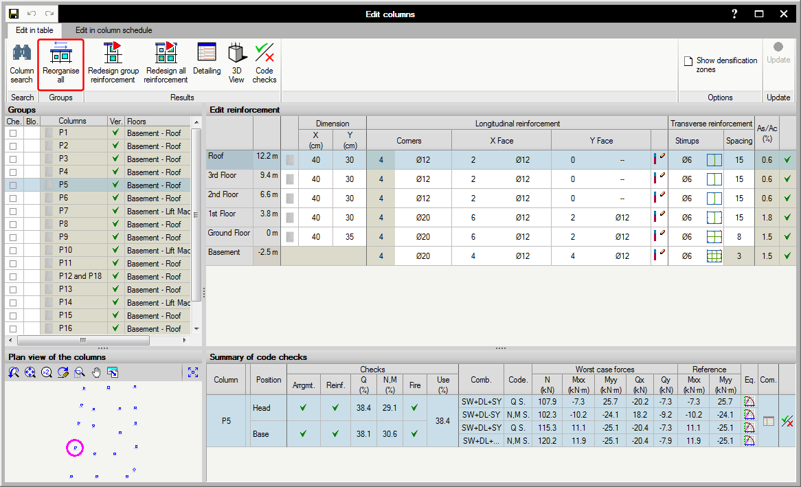
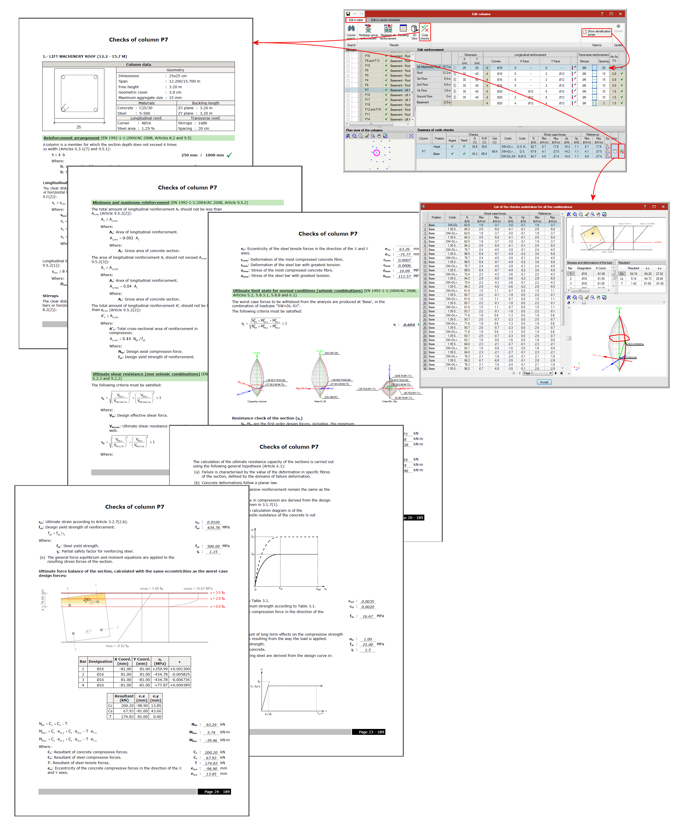
This window allows users to edit a column in a table (top right section of the window) which displays all the spans of the selected column. A summary of the checks carried out on the column span selected in the previous table is also displayed (in the bottom right section of the window).
It is also very useful to show the ultimate limit state (U.L.S.) checks of the selected column span or all the spans of the column.
Some buttons are displayed in the top right section, which allow users to: search for a column, redesign the reinforcement of a group of columns, view the details of the selected column, see its 3D view and obtain the U.L.S. check report of all the spans of the selected column.
Included in the top right section of the editor is the “Show densification zones”, which shows or hides, in the edit reinforcement window (top right section), the stirrup spans a concrete or composite column may have. This option only displays the stirrup densification zones each column span may contain but does not allow users to add any other densification zones. This is only possible in the Edit in column schedule window.
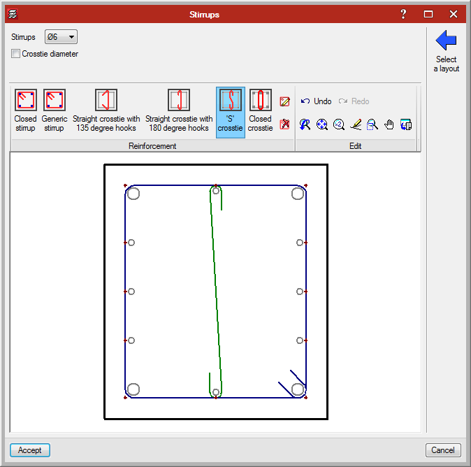
When stirrups are edited (by clicking on the stirrup layout in the table), a dialogue box opens where users can add different types of stirrups and crossties to a column span, hence the stirrups of the column can be modified even though their arrangement is not included in the reinforcement tables. This editing option is also available in the Edit in column schedule window.
Users can also edit the longitudinal reinforcement splices of each span and indicate that the splice length of 50% of the bars (of opposite sides or alternate bars) is to be displaced by a specific distance. To do so, select the icon in the cell located to the right of the “Y face” longitudinal reinforcement. Splices can also be edited and displaced in the Edit in column schedule tab by selecting the “Splices and anchorages” button of the longitudinal reinforcement.

Edit in column schedule
This window has been especially designed to edit the reinforcement and steel sections provided in each span of the column groups, and in this case in the view of the column schedule that will be obtained in the drawing.
It contains more editing tools than the “Edit in table” window. Along the top of this window are buttons with which users can:
- Column search
- Filters
This option is very useful when the job contains many column and/or floor groups, since it allows users to select the floors and groups to be displayed. - Groups
The following operations can be carried out in the column schedule, in the schedule itself:
- Join groups
- Divide groups
- Modify groups (to another group)
- Match groups
- Match data (without grouping columns)
- Reorganise groups
- Edit geometry
- Longitudinal reinforcement (for concrete columns and composite columns)
- Edit
- Insert
- Splices and anchorages

- Delete
- Transverse reinforcement (for concrete columns and composite columns)
- Edit

- Insert
- Densification zones
Allows users to modify, add or delete stirrup spacings in a column span. - Delete
- Edit
- Results
- Redesign group reinforcement
- Redesign all reinforcement
- Code check
- Detailing
- 3D view
Detailed information on this powerful CYPECAD and CYPE 3D tool can be found on the “Advanced column editor” webpage. ![]()
Jobs analysed with previous program versions
To avoid problems arising with jobs analysed with versions earlier than the 2016.a version, the new column editor features do not appear until the job has been reanalysed with the new version. If there are any blocked columns, the new features will continue to not appear even if the job has been reanalysed. Therefore, all columns must be unblocked and the job reanalysed to be able to edit columns with the new editor.
- Published on
- 2016.a
Composite steel and concrete columns
As of the 2016.a version, CYPECAD and CYPE 3D can check composite steel and concrete columns. This check is included in the “Composite steel and concrete columns” module described in the “New modules – Composite steel and concrete” columns section on this webpage. ![]()

- Published on
- 2016.a


